Procedures
Before the beginning of this section, common statements are divided into comprehensible and non comprehensible. In short, comprehensible is the statement that can form a hardware circuit, while non comprehensible is the statement that can only be used for simulation.
| category | sentence | Integrability |
|---|---|---|
| Procedure statement | initial | |
| always | √ | |
| Statement block | begin-end | |
| fork-join | ||
| Assignment statement | assign | √ |
| = , <= | √ | |
| Conditional statement | if - else | √ |
| case, casez, casex | √ | |
| Circular statement | forever | |
| repeat | ||
| while | ||
| for | √ | |
| Compile wizard statement | 'define | √ |
| 'include | √ | |
| 'ifdef, 'else, 'endif | √ |
Always blocks(combinaitonal)
-
Problem Statement
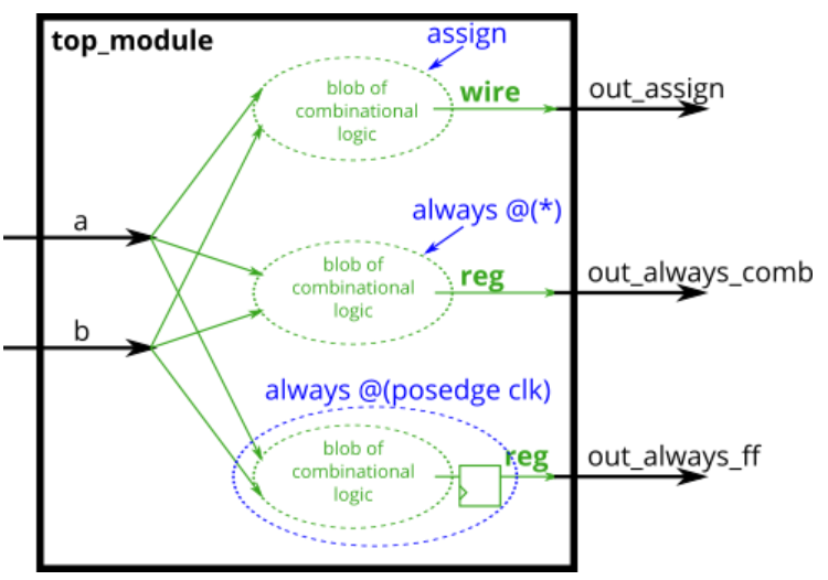
Build an AND gate using both an assign statement and a combinational always block.
-
Code Block
// synthesis verilog_input_version verilog_2001 module top_module( input a, input b, output wire out_assign, output reg out_alwaysblock ); assign out_assign = a && b; always @(*) out_alwaysblock = a && b;//It has the same effect as assign, but the signal is of register type endmodule -
Key Point
The always statement is always running. As long as the sensitive time after the statement is met, the always statement block will be executed. Its syntax format is:
Always @ (< list of sensitive events >)
Statement block;
The list of sensitive events can be:
@(*) / / any signal of the module changes
@(a) / / when signal a changes
@(a or b) / / when signal a or B changes
@(posedge clk) / / triggered by the rising edge of clk signal
@(posedge clk or negedge clk) / / triggered by the rising edge of clk signal or the falling edge of clk signal
In procedure statements (initial and always), the assigned signal must be of type "register", such as' reg '.
In a continuous assignment statement, the assigned signal must be a "wired" data type, such as' wire '.
When using the always statement, all sensitive events that can trigger the always statement must be written in parentheses.
Always blocks(clocked)
-
Problem Statement
Build an XOR gate three ways, using an assign statement, a combinational always block, and a clocked always block. Note that the clocked always block produces a different circuit from the other two: There is a flip-flop so the output is delayed.
-
Code Block
// synthesis verilog_input_version verilog_2001 module top_module( input clk, input a, input b, output wire out_assign, output reg out_always_comb, output reg out_always_ff ); assign out_assign = a ^ b; always @(*) out_always_comb = a^b; always @(posedge clk) out_always_ff <= a^b; endmodule -
Key Point
Procedure statement assignment includes:
Blocking process assignment statement "variable = expression";
Non blocking procedure assignment statement "variable < = expression".
Blocking assignment statements and non blocking assignment statements can only be used in statement blocks.
The blocking assignment statement is characterized by:
① In the serial statement block, it is executed according to the code sorting order, and in the parallel statement block, it is executed at the same time. There is no order.
② The order in which the statements are executed is to first calculate the right side of the equation, and then immediately assign the calculated value to the left.
The non blocking assignment statement is characterized by:
① In any case, it is parallel and there is no sequential relationship
② The order of executing statements is to calculate the right side of the equation first, and then assign the calculated value to the left variable after the delay time is over.
Only in the case of "behavior level modeling + serial statement block + blocking assignment", the code will be serialized
If statement
-
Problem Statement
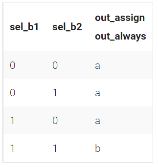
Build a 2-to-1 mux that chooses between a and b. Choose b if both sel_b1 and sel_b2 are true. Otherwise, choose a. Do the same twice, once using assign statements and once using a procedural if statement.
-
Code Block
// synthesis verilog_input_version verilog_2001 module top_module( input a, input b, input sel_b1, input sel_b2, output wire out_assign, output reg out_always ); always @(*) begin if (sel_b1 & sel_b2 ) begin out_always = b; end else begin out_always = a; end end assign out_assign = (sel_b1 && sel_b2)?b:a; endmodule -
Key Point
The serial statement block adopts the keywords "begin" and "end". If the code uses the blocking assignment statement "=", it is executed serially.
if conditional statements have three expressions:
if(Conditional expression) Statement block;
if(Conditional expression)	Statement block;
else		   Statement block;
if(Conditional expression 1)			Statement block;
else if	(Conditional expression 1)	Statement block;
......
else				   Statement block;
If statements are prioritized and executed from top to bottom. If the previous conditions have been met, the whole if statement block will be directly jumped out, and all else if statements will not be read in order.
It is recommended to use the begin end statement block in the statement block of if, even if there is only one line of code.
If statement latches
-
Problem Statement
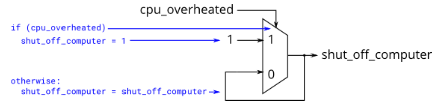
The following code contains incorrect behaviour that creates a latch. Fix the bugs so that you will shut off the computer only if it's really overheated, and stop driving if you've arrived at your destination or you need to refuel.
-
Code Block
// synthesis verilog_input_version verilog_2001 module top_module ( input cpu_overheated, output reg shut_off_computer, input arrived, input gas_tank_empty, output reg keep_driving ); // always @(*) begin if (cpu_overheated) begin shut_off_computer = 1; end else begin shut_off_computer = 0; end end always @(*) begin if (~arrived) begin keep_driving = ~gas_tank_empty; end else begin keep_driving = 0; end end endmodule -
Key Point
When designing a circuit, we cannot expect the code to automatically generate the correct circuit, even if the code does not report an error when compiling, as shown in the following error:
If (cpu_overheated) then shut_off_computer = 1;
If (~arrived) then keep_driving = ~gas_tank_empty;
Because in verilog, if the if condition is not satisfied and the corresponding else is not written, verilog will keep the signal unchanged, and an error signal will be generated.
Therefore, when we write if or case statement blocks, we need to consider all the situations of the circuit.
Case statement
-
Problem Statement
Case statements are more convenient than if statements if there are a large number of cases. So, in this exercise, create a 6-to-1 multiplexer. When sel is between 0 and 5, choose the corresponding data input. Otherwise, output 0. The data inputs and outputs are all 4 bits wide.
-
Code Block
// synthesis verilog_input_version verilog_2001 module top_module ( input [2:0] sel, input [3:0] data0, input [3:0] data1, input [3:0] data2, input [3:0] data3, input [3:0] data4, input [3:0] data5, output reg [3:0] out );// always@(*) begin // This is a combinational circuit case(sel) 3'b000 : begin out = data0; end 3'b001 : begin out = data1; end 3'b010 : begin out = data2; end 3'b011 : begin out = data3; end 3'b100 : begin out = data4; end 3'b101 : begin out = data5; end default :begin out = 3'b000; end endcase end endmodule -
Key Point
case is a multi branch selection control statement more convenient than if else statement, and its syntax expression is:
case(Control expression)
    value A: Statement block;
    value B: Statement block;
    ...
    value N: Statement block;
    default: Statement block;
endcase
The values A to N must be different, but the statement blocks can be the same.
Once the case judges that the statement of a certain value is executed, the case statement block will jump out and will not be traversed completely.
Only when all possible references of sensitive expressions are listed, otherwise the default option will be written.
The bit width between values must be the same
Priority encoder
-
Problem Statement
For this problem, if none of the input bits are high (i.e., input is zero), output zero. Note that a 4-bit number has 16 possible combinations
-
Code Block
// synthesis verilog_input_version verilog_2001 module top_module ( input [3:0] in, output reg [1:0] pos ); always@(*) begin case(in) 4'b0010, 4'b0110, 4'b1010, 4'b1110 : begin pos = 2'd1; end 4'b0100, 4'b1100: begin pos = 2'd2; end 4'b1000 : begin pos = 2'd3; end default: begin pos = 2'd0; end endcase end endmodule -
Key Point
If there are consecutive values between case s that execute the same sentence block, the values can be separated directly by commas.
case is essentially a numerical matching, so there can be another idea to directly compare whether there is' 1 'at each position of the vector, as shown below:
module top_module (
    input [3:0] in,
    output reg [1:0] pos  );

    always@(*) begin
        case(1)
            in[0] : begin
                pos = 2'd0;
            end
            in[1] : begin
                pos = 2'd1;
            end
            in[2] : begin
                pos = 2'd2;
            end
            in[3] : begin
                pos = 2'd3;
            end
            default : begin
            	pos = 2'd0;
            end
        endcase
    end

endmodule
Note: it cannot be written as follows.
// synthesis verilog_input_version verilog_2001
module top_module (
    input [3:0] in,
    output reg [1:0] pos  );

    always@(*) begin
        case(1)
            in[1] : begin
                pos = 2'd1;//4'b0011 will be incorrectly used as the control value
            end
            in[2] : begin
                pos = 2'd2;//4'b0101 will be incorrectly used as the control value
            end
            in[3] : begin
                pos = 2'd3;//4'b1001 will be incorrectly used as the control value
            end
            default : begin
            	pos = 2'd0;
            end
        endcase
    end

endmodule
Priority encoder with casez
-
Problem Statement
Build a priority encoder for 8-bit inputs. Given an 8-bit vector, the output should report the first bit in the vector that is 1. Report zero if the input vector has no bits that are high.
-
Code Block
// synthesis verilog_input_version verilog_2001 module top_module ( input [7:0] in, output reg [2:0] pos ); always@(*) begin casez (in) 8'bzzzzzzz1 : begin pos = 3'd0; end 8'bzzzzzz1z : begin pos = 3'd1; end 8'bzzzzz1zz : begin pos = 3'd2; end 8'bzzzz1zzz : begin pos = 3'd3; end 8'bzzz1zzzz : begin pos = 3'd4; end 8'bzz1zzzzz : begin pos = 3'd5; end 8'bz1zzzzzz : begin pos = 3'd6; end 8'b1zzzzzzz : begin pos = 3'd7; end default : begin pos = 3'd0; end endcase end endmodule -
Key Point
When you don't care about the numerical relationship of other positions in the vector, you can use casez and replace the numerical positions you don't care with z.
Because case is executed from top to bottom, it will exit once matched. Therefore, when writing the value of sensitive expression, pay attention to the order. The error example is as follows:
// synthesis verilog_input_version verilog_2001
module top_module (
    input [7:0] in,
    output reg [2:0] pos  );
    always@(*) begin
        casez (in)
            8'bzzzzzz1z : begin
                pos = 3'd1;//Because the position is changed with 8'bzzz1, when 8'bzzz11 appears, it will match here and exit directly, and will not match below.
            end
            8'bzzzzzzz1 : begin
                pos = 3'd0;
            end
            8'bzzzzz1zz : begin
                pos = 3'd2;
            end
            8'bzzzz1zzz : begin
                pos = 3'd3;
            end
            8'bzzz1zzzz : begin
                pos = 3'd4;
            end
            8'bzz1zzzzz : begin
                pos = 3'd5;
            end
            8'bz1zzzzzz : begin
                pos = 3'd6;
            end
            8'b1zzzzzzz : begin
                pos = 3'd7;
            end
            default : begin
                pos = 3'd0;
            end
        endcase
    end
endmodule
Avoiding latches
-
Problems Statement
Suppose you're building a circuit to process scancodes from a PS/2 keyboard for a game. Given the last two bytes of scancodes received, you need to indicate whether one of the arrow keys on the keyboard have been pressed. This involves a fairly simple mapping, which can be implemented as a case statement (or if-elseif) with four cases.
Your circuit has one 16-bit input, and four outputs. Build this circuit that recognizes these four scancodes and asserts the correct output.
Problem diagram (transferred from HDLBits)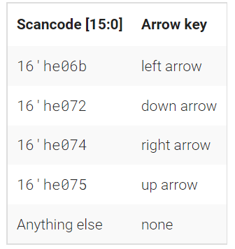
-
Code Block
// synthesis verilog_input_version verilog_2001 module top_module ( input [15:0] scancode, output reg left, output reg down, output reg right, output reg up ); always@(*) begin up = 1'b0; down = 1'b0; left = 1'b0; right = 1'b0; case(scancode) 16'he06b : begin left = 1; end 16'he072 : begin down = 1; end 16'he074 : begin right = 1; end 16'he075 : begin up = 1; end /* default : begin left = 0; down = 0; right = 0; up = 0; end*/ endcase end endmodule -
Key Point
When the situation is very complex, a simple default is not enough. We must assign values to four outputs in case item and default, which will lead to a lot of unnecessary coding.
Therefore, we can assign an initial value to the output first, which can ensure that the output is assigned under all possible circumstances, unless the case statement overrides the assignment, so there is no need to write the default item.
Integer is expressed as follows:
numerical value cardinality symbol Binary B or B octal number system O or o decimal system D or D hexadecimal H or H
More Verilog Features
Conditional ternary operator
-
Problem Statement
Given four unsigned numbers, find the minimum. Unsigned numbers can be compared with standard comparison operators (a < b). Use the conditional operator to make two-way min circuits, then compose a few of them to create a 4-way min circuit. You'll probably want some wire vectors for the intermediate results.
-
Code Block
module top_module (
    input [7:0] a, b, c, d,
    output [7:0] min);//
    // assign intermediate_result1 = compare? true: false;
    wire [7:0] temp_num1 , temp_num2;
    assign temp_num1 = (a>b ? b:a);
    assign temp_num2 = (c>d ? d:c);
    assign min       = (temp_num1 > temp_num2 ? temp_num2 : temp_num1);

endmodule
Reduction operators
-
Problem Statement
Parity checking is often used as a simple method of detecting errors when transmitting data through an imperfect channel. Create a circuit that will compute a parity bit for a 8-bit byte (which will add a 9th bit to the byte). We will use "even" parity, where the parity bit is just the XOR of all 8 data bits.
-
Code Block
module top_module ( input [7:0] in, output parity); assign parity = ^in;//Parity check endmodule -
Key Point
The bit reduction operator can perform sum, or exclusive or and other operations on each bit of the vector to produce a bit output, as shown below:
& a[3:0]     // Sum operation: a [3] & A [2] & A [1] & A [0]. Equivalent to (a[3:0] == 4'hf)
| b[3:0]     // Or operation: b[3]|b[2]|b[1]|b[0]. Equivalent to (B [3:0]! = 4'h0)
^ c[2:0]     // XOR operation: c[2]^c[1]^c[0]. Parity check can be performed
Reduction : Even wider gates
-
Problem Statement
Build a combinational circuit with 100 inputs, in[99:0].
There are 3 outputs:
- out_and: output of a 100-input AND gate.
- out_or: output of a 100-input OR gate.
- out_xor: output of a 100-input XOR gate.
-
Code Block
module top_module(
    input [99:0] in,
    output out_and,
    output out_or,
    output out_xor
);
    assign out_and = ∈
    assign out_or  = |in;
    assign out_xor = ^in;

endmodule
Combinational for-loop: Vector reversal 2
-
Problem Statement
Given a 100-bit input vector [99:0], reverse its bit ordering.
-
Code Block
module top_module( input [99:0] in, output [99:0] out ); integer i; always @(*)begin for(i=0;i<100;i++) begin out[i] = in[99-i]; end end endmodule -
Key Point
The syntax format of 'for' conditional loop is:
integer Integer variable
for (Initial value of cyclic variable; Cycle end condition; Cyclic variable increment)
Combinational for-loop: 255-bit population count
-
Problem Statement
A "population count" circuit counts the number of '1's in an input vector. Build a population count circuit for a 255-bit input vector.
-
Code Block
module top_module(
    input [254:0] in,
    output [7:0] out );

    integer i;
    always @(*) begin
        out = 8'd0;
        for(i=0; i<255; i++)begin
            out += in[i];
        end
    end
endmodule
Generate for-loop: 100-bit binary adder2
-
Problem Statement
Create a 100-bit binary ripple-carry adder by instantiating 100 full adder. The adder adds two 100-bit numbers and a carry-in to produce a 100-bit sum and carry out. To encourage you to actually instantiate full adders, also output the carry-out from each full adder in the ripple-carry adder. cout[99] is the final carry-out from the last full adder, and is the carry-out you usually see.
-
Code Block
module top_module( input [99:0] a, b, input cin, output [99:0] cout, output [99:0] sum ); genvar i; generate for(i=0; i<100; i++) begin : adder //name if(i == 0)begin assign {cout[0], sum[0]} = a[0] + b[0] + cin; end else begin assign {cout[i], sum[i]} = a[i] + b[i] + cout[i-1]; end end endgenerate endmodule -
Key Point
The main function of generate statement is to copy module, reg, assign, always, task and other statements or modules.
Generate statements include generate for, generate if, and generate case statements.
Precautions for generate statement block:
generate Not on always Block, but always Blocks, etc. are included in generate Medium;
generate for In, to be in begin It is mandatory to name the module later, and it is also necessary to assign the name when generating multiple instances with circular generation statements;
task Can't put it in generatefor In order to realize the same function, sub modules are used;
Loop generation in progress for Statement must use genvar Keyword definition, genvar Keywords can be written in generate Outside the statement, it can also be written in generate In the statement, as long as it precedes for Statement declaration is sufficient,And genvar Keyword defines only variables generate Statement blocks can be used;
for The content of the statement must be begin-end,Even if there is only one statement, it cannot be omitted. This is also a mandatory requirement, and naming the loop is also inseparable begin keyword;
Generate for-loop: 100-digit BCD adder
-
Problem statement
You are provided with a BCD one-digit adder named bcd_fadd that adds two BCD digits and carry-in, and produces a sum and carry-out.
module bcd_fadd {
    input [3:0] a,
    input [3:0] b,
    input     cin,
    output   cout,
    output [3:0] sum );
Instantiate 100 copies of bcd_fadd to create a 100-digit BCD ripple-carry adder. Your adder should add two 100-digit BCD numbers (packed into 400-bit vectors) and a carry-in to produce a 100-digit sum and carry out.
-
Code Block
module top_module(
    input [399:0] a, b,
    input cin,
    output cout,
    output [399:0] sum );
    wire [99:0] cout_temp;
	genvar i;
    generate
        for(i=0;i<100;i++) begin:adder
            if(i == 0)	begin
                bcd_fadd bcd_inst(a[3:0],b[3:0],cin,cout_temp[0],sum[3:0]);
            end
            else	begin
                bcd_fadd bcd_inst(a[4*i+3:4*i],b[4*i+3:4*i],cout_temp[i-1],cout_temp[i],sum[4*i+3:4*i]);
            end
        end
        assign cout=cout_temp[99];
    endgenerate
endmodule