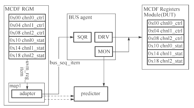
UVM register model integration
- The bus interface timing of MCDF access register is relatively simple. The control register interface first needs to parse cmd at each clock. When cmd is a write instruction, you need to cmd the data_ data_ Write in to cmd_ In the register corresponding to addr. When cmd is a read instruction, you need to read from cmd_addr reads data from the register used for the pair. In the next cycle, cmd_ The register data corresponding to addr is transmitted to cmd_data_out interface.
Bus UVC implementation code
- The following gives the bus UVC implementation code of 8-bit address line and 32-bit data line at one end.
class mcdf_bus_trans extends uvm_sequence_item;
	rand bit [1:0]cmd;
	rand bit [7:0]addr;
	rand bit [31:0]wdata;
	bit [31:0]rdata;
	`uvm_object_utils_begin(mcdf_bus_trans)
	...
	`uvm_object_utils_end
	...
endclass
class mcdf_bus_sequencer extends uvm_sequencer;
	virtual mcdf_if vif;
	`uvm_component_utils(mcdf_bus_sequencer)
	...
	function void build_phase(uvm_phase phase);
		if(!uvm_config_db#(virtual mcdf_if)::get(this,"","vif",vif))begin
			`uvm_error("GETVIF","no virtual interface is assigned")
		end
	endfunction
endclass

class mcdf_bus_monitor extends uvm_monitor;
	virtual mcdf_vif vif;
	uvm_analysis_port #(mcdf_bus_trans) ap;
	`uvm_component_utils(mcdf_bus_monitor)
	...
	function void build_phase(uvm_phase phase);
		if(!uvm_config_db#(virtual mcdf_if)::get(this,"","vif",vif))begin
			`uvm_error("GETVIF","no virtual interface is assigned")
		end
		ap=new("ap",this);
	endfunction
	task run_phase(uvm_phase phase);
		forever begin
			mon_trans();
		end
	endtask
	task mon_trans();
		mcdf_bus_trans t;
		@(posedge vif.clk);
		if(vif.cmd==`WRITE)begin
			t=new();
			t.cmd=`WRITE;
			t.addr=vif.addr;
			t.wdata=vif.wdata;
			ap.write(t);
		end
		else if(vif.cmd=`READ) begin
			t=new();
			t.cmd=`READ;
			t.addr=vif.addr;
			fork
				begin
					@(posedge vif.clk)
					#10ps;
					t.rdata=vif.rdata;
					ap.write(t);
				end
			join_none
		end
	endtask
endclass:mcdf_bus_monitor

class mcdf_bus_driver extends uvm_driver;
	virtual mcdf_if vif;
	`uvm_component_utils(mcdf_bus_driver)
	...
	function void build_phase(uvm_phase phase);
		if(!uvm_config_db#(virtual mcdf_if)::get(this,"","vif",vif))begin
			`uvm_error("GETVIF","no virtual interface is assigned")
		end
	endfunction
	task run_phase(uvm_phase phase);
		REQ tep;
		mcdf_bus_trans req,rsp;
		reset_listener();
		forever begin
			seq_item_port.get_next_item(tmp);
			void'($cast(req,tmp));
			`uvm_info("DRV",$sformatf("got a item\n %s",req.sprint()),UVM_LOW)
			void'($cast(rsp,req.clone()));
			rsp.set_sequence_id(req.get_sequence_id());
			rsp.set_transcation_id(req.get_transaction_id());
			drive_bus(rsp);
			seq_item_port.item_done(rsp);
			`uvm_info("DRV",$sformatf("sent a item\n %s",rsp.sprint()),UVM_LOW)
		end
	endtask
	task reset_listener();
		fork
			forever begin
				@(negedge vif.rstn)drive_idle();
			end
		join_none
	endtask
	task drive_bus(mcdf_bus_trans t);
		cast(t.cmd)
			`WRITE:drive_write(t);
			`READ:drive_read(t);
			`IDLE:drive_idle(1);
			default:`uvm_error("DRIVE","invalid mcdf command type received!")
		endcase
	endtask
	task drive_write(mcdf_bus_trans t);
		@(posedge vif.clk);
		vif.cmd<=t.cmd;
		vif.addr<=t.addr;
		vif.wdata<=t.wdata;
	endtask
	task drive_read(mcdf_bus_trans t);
		@(posedge vif.clk);
		vif.cmd<=t.cmd;
		vif.addr<=t.addr;
		@(posedge vif.clk);
		#10ps;
		t.rdata=vif.rdata;
	endtask
	task drive_idle(bit is_sync=0);
		if(is_sync)@(posedge vif.clk);
			vif.cmd<='h0;
			vif.addr<='h0;
			vif.wdata<='h0;
	endtask
endclass

class mcdf_bus_agent extends uvm_agent;
	mcdf_bus_driver driver;
	mcdf_bus_sequencer sequencer;
	mcdf_bus_monitor monitor;
	`uvm_component_utils(mcdf_bus_agent)
	...
	function void build_phase(uvm_phase phase);
		driver=mcdf_bus_driver::type_id::create("driver",this);
		sequencer=mcdf_bus_sequencer ::type_id::create("sequencer",this);
		monitor=mcdf_bus_monitor ::type_id::create("monitor",this);
	endfunction
	function void connect_phase(uvm_phase phase);
		driver.seq_item_port.connect(sequencer.seq_item_export);
	endfunction
endclass
Examples include MCDF_ bus_ All components of agent: sequence item, sequencer, driver, monitor and agent. We explain some implementations of these codes:
- mcdf_bus_trans includes randomizable data members cmd, addr, wdata and non randomizable rdata. Rdata is not declared as a rand type because it should be read or observed from the bus and should not be randomized.
- mcdf_ bus_ The monitor will observe the bus, then write it out to the target analysis component through the analysis port, and connect to the UVM later in this section_ reg_ predictor.
- mcdf_bus_driver mainly realizes the bus drive and reset functions, and resets through the modular method_ listener(),drive_bus(),drive_write(),drive_read() and drive_idle() can parse three command modes: IDLE, WRITE, and READ. In the READ mode, the READ back data is passed through item_done(rsp) writes back to the sequencer and sequence sides. It is recommended that readers create RSP objects through the clone() command and then use set_sequence_id() and set_ transaction_ The ID () functions ensure that the ID information retained in REQ and RSP is consistent.
MCDF register design code
MCDF register design code:
param_def.v
`define  ADDR_WIDTH 8
`define  CMD_DATA_WIDTH 32

`define  WRITE 2'b10          //Register operation command
`define  READ  2'b01
`define  IDLE  2'b00

`define SLV0_RW_ADDR 8'h00    //Register address
`define SLV1_RW_ADDR 8'h04
`define SLV2_RW_ADDR 8'h08
`define SLV0_R_ADDR  8'h10
`define SLV1_R_ADDR  8'h14
`define SLV2_R_ADDR  8'h18


`define SLV0_RW_REG 0
`define SLV1_RW_REG 1
`define SLV2_RW_REG 2
`define SLV0_R_REG  3
`define SLV1_R_REG  4
`define SLV2_R_REG  5

`define FIFO_MARGIN_WIDTH 8

`define PRIO_WIDTH 2
`define PRIO_HIGH 2
`define PRIO_LOW  1

`define PAC_LEN_WIDTH 3
`define PAC_LEN_HIGH 5
`define PAC_LEN_LOW  3
reg.v
   module ctrl_regs(	clk_i,
						rstn_i,
						cmd_i,
						cmd_addr_i,
						cmd_data_i,
						cmd_data_o,
			      		slv0_pkglen_o,
						slv1_pkglen_o,
						slv2_pkglen_o,
			     		slv0_prio_o,
						slv1_prio_o,
						slv2_prio_o,
						slv0_margin_i,
						slv1_margin_i,
						slv2_margin_i,
					 	slv0_en_o,
						slv1_en_o,
						slv2_en_o);

input clk_i;
input rstn_i;
input [1:0] cmd_i;
input [`ADDR_WIDTH-1:0]  cmd_addr_i;
input [`CMD_DATA_WIDTH-1:0]  cmd_data_i;
input [`FIFO_MARGIN_WIDTH-1:0] slv0_margin_i;
input [`FIFO_MARGIN_WIDTH-1:0] slv1_margin_i;
input [`FIFO_MARGIN_WIDTH-1:0] slv2_margin_i;

reg [`CMD_DATA_WIDTH-1:0] mem [5:0];
reg [`CMD_DATA_WIDTH-1:0] cmd_data_reg;

output  [`CMD_DATA_WIDTH-1:0] cmd_data_o;
output  [`PAC_LEN_WIDTH-1:0]  slv0_pkglen_o;
output  [`PAC_LEN_WIDTH-1:0]  slv1_pkglen_o;
output  [`PAC_LEN_WIDTH-1:0]  slv2_pkglen_o;
output  [`PRIO_WIDTH-1:0]  slv0_prio_o;
output  [`PRIO_WIDTH-1:0]  slv1_prio_o;
output  [`PRIO_WIDTH-1:0]  slv2_prio_o;
output   slv0_en_o;
output   slv1_en_o;
output   slv2_en_o;

always @ (posedge clk_i or negedge rstn_i) //Trace fifo's margin
begin
  if (!rstn_i)
    begin
      mem [`SLV0_R_REG] <= 32'h00000020;   //FIFO's depth is 32
      mem [`SLV1_R_REG] <= 32'h00000020;
      mem [`SLV2_R_REG] <= 32'h00000020;
    end
    else
    begin
      mem [`SLV0_R_REG] <= {24'b0,slv0_margin_i};
      mem [`SLV1_R_REG] <= {24'b0,slv1_margin_i};
      mem [`SLV2_R_REG] <= {24'b0,slv2_margin_i};
    end
end

always @ (posedge clk_i or negedge rstn_i) //write R&W register
begin
	if (!rstn_i)
  begin
    mem [`SLV0_RW_REG] = 32'h00000007;
    mem [`SLV1_RW_REG] = 32'h00000007;
    mem [`SLV2_RW_REG] = 32'h00000007;
  end
 else if (cmd_i== `WRITE) begin
				case(cmd_addr_i)
				`SLV0_RW_ADDR: mem[`SLV0_RW_REG]<= {26'b0,cmd_data_i[`PAC_LEN_HIGH:0]};
				`SLV1_RW_ADDR: mem[`SLV1_RW_REG]<= {26'b0,cmd_data_i[`PAC_LEN_HIGH:0]};
				`SLV2_RW_ADDR: mem[`SLV2_RW_REG]<= {26'b0,cmd_data_i[`PAC_LEN_HIGH:0]};
				endcase
			end
end

always@ (posedge clk_i or negedge rstn_i) // read R&W, R register
  if(!rstn_i)
  	  cmd_data_reg <= 32'b0;
		else if(cmd_i == `READ)
      begin
				case(cmd_addr_i)
				`SLV0_RW_ADDR:		cmd_data_reg  <= mem[`SLV0_RW_REG];
				`SLV1_RW_ADDR:		cmd_data_reg  <= mem[`SLV1_RW_REG];
				`SLV2_RW_ADDR:	  cmd_data_reg  <= mem[`SLV2_RW_REG];
				`SLV0_R_ADDR: 		cmd_data_reg  <= mem[`SLV0_R_REG];
				`SLV1_R_ADDR: 		cmd_data_reg  <= mem[`SLV1_R_REG];
				`SLV2_R_ADDR: 		cmd_data_reg  <= mem[`SLV2_R_REG];
				endcase
     end

assign  cmd_data_o  = cmd_data_reg;
assign  slv0_pkglen_o  = mem[`SLV0_RW_REG][`PAC_LEN_HIGH:`PAC_LEN_LOW];
assign  slv1_pkglen_o  = mem[`SLV1_RW_REG][`PAC_LEN_HIGH:`PAC_LEN_LOW];
assign  slv2_pkglen_o  = mem[`SLV2_RW_REG][`PAC_LEN_HIGH:`PAC_LEN_LOW];

assign  slv0_prio_o  = mem[`SLV0_RW_REG][`PRIO_HIGH:`PRIO_LOW];
assign  slv1_prio_o  = mem[`SLV1_RW_REG][`PRIO_HIGH:`PRIO_LOW];
assign  slv2_prio_o  = mem[`SLV2_RW_REG][`PRIO_HIGH:`PRIO_LOW];

assign  slv0_en_o = mem[`SLV0_RW_REG][0];
assign  slv1_en_o = mem[`SLV1_RW_REG][0];
assign  slv2_en_o = mem[`SLV2_RW_REG][0];

endmodule
Register model integration
class reg2mcdf_adapter extends uvm_reg_adapter;
`uvm_object_utils(reg2mcdf_adapter)
function new(string name="mcdf_bus_trans");
super.new(name);
provides_responses=1;
endfunction
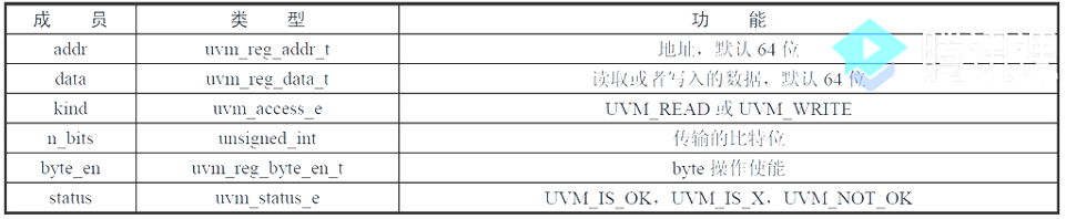
function uvm_sequence_item reg2bus(const ref uvm_reg_bus_op rw);
mcdf_bus_trans t=mcdf_bus_trans::type_id::create("t");
t.cmd=(rw.kind==UVM_WRITE)?`WRITE:`READ;
t.addr=rw.addr;
t.wdata=rw.data;
return t;
endfunction
function void bus2reg(uvm_sequence_item bus_item,ref uvm_reg_bus_op rw);
mcdf_bus_trans t;
if(!$cast(t,bus_item))begin
`uvm_fatal("NOT_MCDF_BUS_TYPE","Provided bus_item is not of the correct type")
return;
end
rw.kind=(t.cmd==`WRITE)?UVM_WRITE:UVM_READ;
rw.addr=t.addr;
rw.data=(t.cmd==`WRITE)?t.wdata:t.rdata;
rw.status=UVM_IS_OK;
endfunction
endclass
- This class enables provide in the build function_ Responses, this is because of MCDF_ bus_ The driver will return the RSP to the sequencer after initiating the bus access.
- The bridging scenario completed by reg2bus() is that if the user operates at the register level, the information of the register level operation uvm_reg_bus_op will be recorded and UVM will be called at the same time_ reg_ Adapter:: reg2bus() function.
- After completing the UVM_ reg_ bus_ Map OP information to MCDF_ bus_ After trans, the function will mcdf_bus_trans instance returns. While returning MCDF_ bus_ After trans, the instance will pass through mcdf_bus_sequencer passed into mcdf_bus_driver. The transaction transfer here is implicitly called in the background and does not need to be initiated by the reader himself.
No matter whether the register is read or written, it should know the status return after the bus operation. For the read operation, it also needs to know the read data returned by the bus, so uvm_reg_adapter::bus2reg() is from mcdf_bus_driver() writes data back to mcdf_bus_sequencer, and consistently keep listening reg2mcdf_ Once the adapter obtains the RSP(mcdf_bus_trans) from the sequencer, it will automatically call the bus2reg() function.
The bus2reg() function is the opposite of reg2bus(), and completes the function from mcdf_bus_trans to UVM_ reg_ bus_ The content mapping of the Op. After the mapping is completed, the updated UVM_ reg_ bus_ The op data is finally returned to the register operation scene layer.
For register operations, whether read operations or write operations, you need to call reg2bus) and then initiate bus transactions. After the bus transaction sends back feedback, you need to call bus2reg() to return the bus data to the register operation level.
adapter integration
class mcdf_bus_env extends uvm_env;
	mcdf_bus_agent agent;
	mcdf_rgm rgm;
	reg2mcdf_adapter reg2mcdf;
	`uvm_component_utils(mcdf_bus_env)
	...
	function void build_phase(uvm_phase phase);
		agent=mcdf_bus_agent::type_id::create("agent",this);
		if(!uvm_config_db#(mcdf_rgm)::get(this,"","rgm",rgm))begin
			`uvm_info("GETVIF","no top-down RGM handle is assigned",UVM_LOW)
			rgm=mcdf_rgm::type_id::create("rgm",this);
			`uvm_info("NEWRGM","created rgm instance locally",UVM_LOW)
		end
		rgm.build();
		rgm.map.set_auto_predict();
		reg2mcdf=reg2mcdf_adapter::type_id::create("reg2mcdf");
	endfunction
	function void connect_phase(uvm_phase phase);
		rgm.map.set_sequencer(agent.sequencer,reg2mcdf);
	endfunction
endclass
register model and adapter are both object s
class test1 extends uvm_test;
	mcdf_rgm rgm;
	mcdf_bus_env env;
	`uvm_component_utils(test1)
	...
	function void build_phase(uvm_phase phase);
		rgm=mcdf_rgm::type_id::create("rgm",this);
		uvm_config_db#(mcdf_rgm)::set(this,"env*","rgm",rgm);
		env=mcdf_bus_env::type_id::create("env",this);
	endfunction
	task run_phase(uvm_phase phase)
	...
	endtask
endclass
Focus on the author
- Readme
The author is a graduate student majoring in digital design at China University of science and technology. His level is limited. If there are mistakes, please correct them and want to make progress with you. - experience
He has won the national scholarship, "Higher Education Society Cup" mathematical modeling national second prize - Update in succession:
1. Follow up content of system verilog related to UVM verification;
2. Some basic module designs related to verilog digital design, such as FIFO, UART, I2C, etc.
3. Research guarantee and competition experience, etc - WeChat official account
Welcome to the official account of "the daily practice of digital IC Xiao Bai". We look forward to fighting with you to travel around the digital IC world.