Bowen catalog
Write before
As a basic knowledge tutorial of the field programmer, how can it be scarce to use this simple and practical seven-segment digital tube display? This blog post is a summary of the past topic!
Note: The tube itself is seven segments, but after adding a decimal point it is eight segments!
text
Principle of seven-segment digital tube
Seven-segment displays are indicators that are often used by field-programmer designers to display information to users.Converting binary files to seven-segment display-compatible code can be easily accomplished in VHDL and Verilog.There are many applications that may require the use of one or more eight-segment displays, such as:
- alarm clock
- Stopwatch
- Button Count Indicator
- Voltage measurement (from analog to digital converter)
Wait!
Here is a diagram of seven segments of the tube: We mark the seven segments as A, B, C, D, E, F, G, and a decimal DP.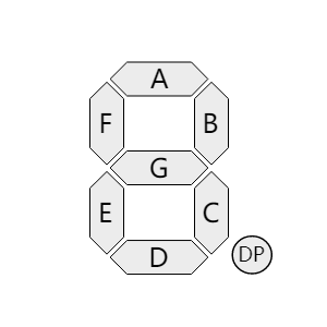
If a reg variable is used to store the bit values of a seven-segment digital tube, a reg variable is defined:
reg [6:0] seg;
Where G corresponds to seg[6], F to seg[5], and A to seg[0], the decimal point is represented by a special dp.
Seven Segments Digital Tube Decoder Table
To display 0 to F, the corresponding decoding table is:
parameter   NUM0     = 7'h3f,//40,
            NUM1     = 7'h06,//79,
            NUM2     = 7'h5b,//24,
            NUM3     = 7'h4f,//30,
            NUM4     = 7'h66,//19,
            NUM5     = 7'h6d,//12,
            NUM6     = 7'h7d,//02,
            NUM7     = 7'h07,//78,
            NUM8     = 7'h7f,//20,
            NUM9     = 7'h6f,//10,
            NUMA     = 7'h77,//08,
            NUMB     = 7'h7c,//03,
            NUMC     = 7'h39,//46,
            NUMD     = 7'h5e,//21,
            NUME     = 7'h79,//06,
            NUMF     = 7'h71,//0e;
Note that the decoding table for the common cathode is in the front part, and the decoding table for the common anode is commented out in the back part!
The so-called common anode is shown in the following schematic diagram:
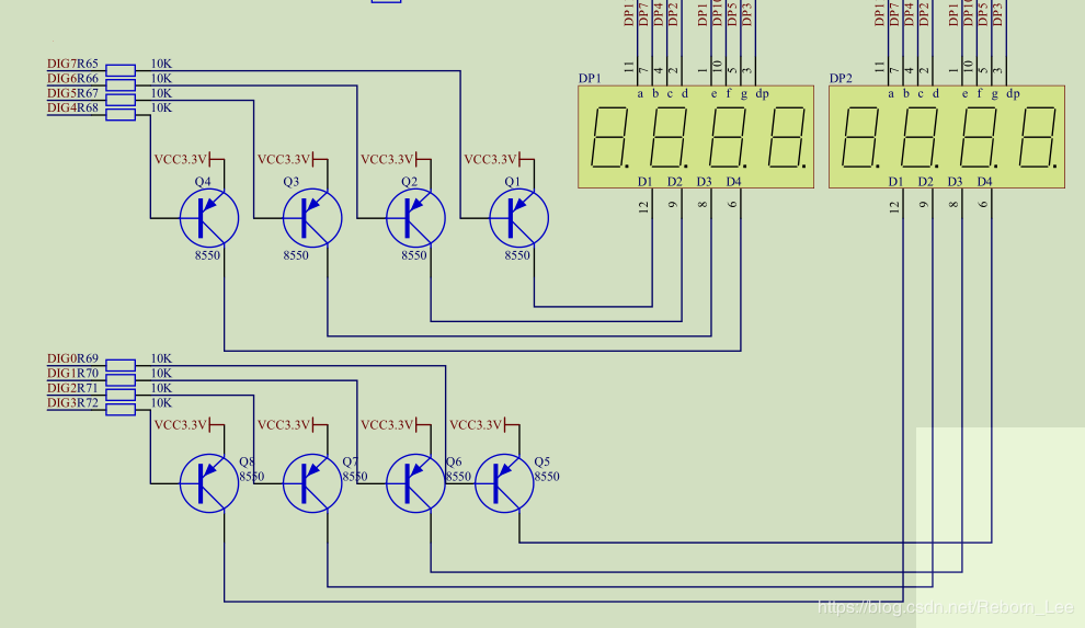
The collector of the transistor connects to the power supply, and the low level of the chip selection is effective. When the chip selection is made, the transistor conducts and the common end of the digital tube connects to the high level, so the segment selection is low and the corresponding segment is bright.
verilog design for single seven-segment digital tube display
For a common cathode example, the Verilog design for a single digital tube display is:
module Binary_To_7Segment
  (
   input       i_Clk,
   input [3:0] i_Binary_Num,
   input 	   i_dp, //Decimal point input
   output      o_Segment_A,
   output      o_Segment_B,
   output      o_Segment_C,
   output      o_Segment_D,
   output      o_Segment_E,
   output      o_Segment_F,
   output      o_Segment_G,
   output      o_dp
   );

  reg [6:0]    r_Hex_Encoding = 7'h00;

  // Purpose: Creates a case statement for all possible input binary numbers.
  // Drives r_Hex_Encoding appropriately for each input combination.
  always @(posedge i_Clk)
    begin
      case (i_Binary_Num)
        4'b0000 : r_Hex_Encoding <= 7'h3f;
        4'b0001 : r_Hex_Encoding <= 7'h06;
        4'b0010 : r_Hex_Encoding <= 7'h5b;
        4'b0011 : r_Hex_Encoding <= 7'h4f;
        4'b0100 : r_Hex_Encoding <= 7'h66;
        4'b0101 : r_Hex_Encoding <= 7'h6d;
        4'b0110 : r_Hex_Encoding <= 7'h7d;
        4'b0111 : r_Hex_Encoding <= 7'h07;
        4'b1000 : r_Hex_Encoding <= 7'h7f;
        4'b1001 : r_Hex_Encoding <= 7'h6f;
        4'b1010 : r_Hex_Encoding <= 7'h77;
        4'b1011 : r_Hex_Encoding <= 7'h7c;
        4'b1100 : r_Hex_Encoding <= 7'h39;
        4'b1101 : r_Hex_Encoding <= 7'h5e;
        4'b1110 : r_Hex_Encoding <= 7'h79;
        4'b1111 : r_Hex_Encoding <= 7'h71;
      endcase
    end // always @ (posedge i_Clk)

  // r_Hex_Encoding[7] is unused
  assign o_Segment_A = r_Hex_Encoding[0];
  assign o_Segment_B = r_Hex_Encoding[1];
  assign o_Segment_C = r_Hex_Encoding[2];
  assign o_Segment_D = r_Hex_Encoding[3];
  assign o_Segment_E = r_Hex_Encoding[4];
  assign o_Segment_F = r_Hex_Encoding[5];
  assign o_Segment_G = r_Hex_Encoding[6];
  assign o_dp = i_dp;

endmodule // Binary_To_7Segment
Dynamic Scan Display with Multiple Digital Tubes
To describe the dynamic scan display of multiple digital tubes in one sentence, that is, as long as you flash fast enough, you can't see I'm gone!
This is the case with dynamic scan display. The dynamic display of the digital tube is that each tube is illuminated alternately by time-sharing multiplexing, and only one tube is illuminated at the same time.
Time-sharing multiplexed scans show that the visual persistence of the human eye is utilized. If the control signal on the public side refreshes fast enough, the human eye will not distinguish the flicker of the LED and thinks that the four digital tubes are illuminated at the same time.
The following is a schematic diagram of multiple digital tube connections:

The refresh speed of the chip selection control signal must be fast enough to avoid flickering sensation, but not too fast to avoid affecting the switch switch switch of the digital tube. The best operating frequency is about 1000Hz.If the clock of a field bus is 50MHz, then run at least 5*10^4 cycles, that is, 50,000 cycles refresh once. We know 2^16=65536,2^15=32768.
Let's choose a counter bit width of 16 to try!
Note: The effect can actually be determined by the board test, as the development board is not in hand now, it has not been verified yet.
The code uses 18-bit binary number, high 2-bit control slice selection, low 16-bit count full once, carry once, high 2-bit change 00-01-10-11-00-..., select one of the tube, and use the case statement to complete this function.
The hex0, hex1, hex2, hex3 in the code below are input signals to control the number displayed on the digital tube, dp_in is used to control the illumination and extinction of decimal points.
`timescale 1ns / 1ps
module scan_led_hex_disp(
    input clk,
    input reset,
    input [3:0] hex0, //Number displayed by the first digital tube
    input [3:0] hex1,
    input [3:0] hex2,
    input [3:0] hex3,
    input [3:0] dp_in, //demand control
    output reg [3:0] an,   //Picture Selection
    output reg [7:0] sseg  //Segment Selection
    );

	localparam N = 18; //50 Mhz clock crossover using low 16 bits (50MHZ/2^16)
	reg [N-1:0] regN; //High two bits as control signal and low 16 bits as counter to divide clock frequency
	reg [3:0] hex_in; //Segment Selection Control Signal
	reg dp;

	always@(posedge clk, posedge reset)
	begin
		if(reset)
			regN <= 0;
		else
			regN <= regN + 1;
	end

	always@ *
	begin
		case(regN[N-1:N-2])
		2'b00:begin
			an = 4'b1110; //Select 1st Digital Tube
			hex_in = hex0; //The number displayed by the tube is hex_in control, showing the number entered by hex0;
			dp = dp_in[0]; //Control the decimal point of the tube
		end
		2'b01:begin
			an = 4'b1101; //Select the second tube
			hex_in = hex1;
			dp = dp_in[1];
		end
		2'b10:begin
			an = 4'b1011;
			hex_in = hex2;
			dp = dp_in[2];
		end
		default:begin
			an = 4'b0111;
			hex_in = hex3;
			dp = dp_in[3];
		end

		endcase

	end
	always@ *
	begin
		case(hex_in)
			4'h0: sseg[6:0] = 7'b0000001; //Common anode digital tube
			4'h1: sseg[6:0] = 7'b1001111;
			4'h2: sseg[6:0] = 7'b0010010;
			4'h3: sseg[6:0] = 7'b0000110;
			4'h4: sseg[6:0] = 7'b1001100;
			4'h5: sseg[6:0] = 7'b0100100;
			4'h6: sseg[6:0] = 7'b0100000;
			4'h7: sseg[6:0] = 7'b0001111;
			4'h8: sseg[6:0] = 7'b0000010;
			4'h9: sseg[6:0] = 7'b0000100;
			4'ha: sseg[6:0] = 7'b0001000;
			4'hb: sseg[6:0] = 7'b1100000;
			4'hc: sseg[6:0] = 7'b0110001;
			4'hd: sseg[6:0] = 7'b1000010;
			4'he: sseg[6:0] = 7'b0110000;
			default: sseg[6:0] = 7'b0111000;
		endcase
		sseg[7] = dp;
	end
endmodule
According to the previous section, the Verilog design of a single digital tube display, the last decoding module can use time sequence logic, that is, the code can be changed to:
`timescale 1ns / 1ps
module scan_led_hex_disp(
    input clk,
    input reset,
    input [3:0] hex0, //Number displayed by the first digital tube
    input [3:0] hex1,
    input [3:0] hex2,
    input [3:0] hex3,
    input [3:0] dp_in, //demand control
    output reg [3:0] an,   //Picture Selection
    output reg [7:0] sseg  //Segment Selection
    );

	localparam N = 18; //50 Mhz clock crossover using low 16 bits (50MHZ/2^16)
	reg [N-1:0] regN; //High two bits as control signal and low 16 bits as counter to divide clock frequency
	reg [3:0] hex_in; //Segment Selection Control Signal
	reg dp;

	always@(posedge clk, posedge reset)
	begin
		if(reset)
			regN <= 0;
		else
			regN <= regN + 1;
	end

	always@ *
	begin
		case(regN[N-1:N-2])
		2'b00:begin
			an = 4'b1110; //Select 1st Digital Tube
			hex_in = hex0; //The number displayed by the tube is hex_in control, showing the number entered by hex0;
			dp = dp_in[0]; //Control the decimal point of the tube
		end
		2'b01:begin
			an = 4'b1101; //Select the second tube
			hex_in = hex1;
			dp = dp_in[1];
		end
		2'b10:begin
			an = 4'b1011;
			hex_in = hex2;
			dp = dp_in[2];
		end
		default:begin
			an = 4'b0111;
			hex_in = hex3;
			dp = dp_in[3];
		end

		endcase

	end
	always@(posedge clk)
	begin
		case(hex_in)
			4'h0: sseg[6:0] = 7'b0000001; //Common anode digital tube
			4'h1: sseg[6:0] = 7'b1001111;
			4'h2: sseg[6:0] = 7'b0010010;
			4'h3: sseg[6:0] = 7'b0000110;
			4'h4: sseg[6:0] = 7'b1001100;
			4'h5: sseg[6:0] = 7'b0100100;
			4'h6: sseg[6:0] = 7'b0100000;
			4'h7: sseg[6:0] = 7'b0001111;
			4'h8: sseg[6:0] = 7'b0000010;
			4'h9: sseg[6:0] = 7'b0000100;
			4'ha: sseg[6:0] = 7'b0001000;
			4'hb: sseg[6:0] = 7'b1100000;
			4'hc: sseg[6:0] = 7'b0110001;
			4'hd: sseg[6:0] = 7'b1000010;
			4'he: sseg[6:0] = 7'b0110000;
			default: sseg[6:0] = 7'b0111000;
		endcase
		sseg[7] = dp;
	end
endmodule
Note: There is no uniform naming method due to code migration based on past blogs and reference materials. When there are more than one digital tube display, the digital tube is a common anode digital tube, while a single digital tube display that section, that is, the previous section, the use of the digital tube is a common cathode for example. Therefore, the values of the decoding part of the digital tube are different, please note!
Reference material
Make a friend
-
Personal Wechat Public Number: GA LAB
-
KNOW: LI Ruiboun