Bowen catalog
Write before
The first five articles have already explained Verilog's bits and pieces of knowledge, starting with modules.
Modular design is the core of Verilog and digital design. Modular design is like building blocks to build digital circuits.
This blog, explanatory module uses verilog 2001 revision style, examples are the best way to learn.
- Personal Wechat Public Number: GA LAB
- Personal Blog Home Page
text
Modular
Using Verilog to design digital circuit is to design modules of different sizes, which are instantiated from each other, and finally form a top-level module, that is, the whole design.
The basic module templates are given below:
module module_name(
	input i_clk,
	input i_a,
	input [3:0] i_b,
	input i_en,
	output o_out,
	inout [3:0] o_c
	//your input/ouput/inout ports
);

//your sequential logic
always@(posedge i_clk) begin
//your sequential logic
end

//your combinational logic
always@(*) begin
//your logic
end

assign o_c = i_en ? i_b : 4'hz;
//......

//institation other module
a_module inst(
.i_clk(i_clk),
.i_a(i_a),
.o_c(o_c),
);

endmodule
If the variable bit width within a module is parameterized, the module template is:
module exam_module #(
parameter c_WIDTH = 8,
parameter c_DEPTH = 16
)(
//input
input i_a,
//inout
inout io_b,
//output
output o_c
);

//the same as before module


endmodule
Instantiate modules with parameters:
module top_module(
// input/output/inout ports define
);

//other logics

//institation module with parameter
exam_module #(
.c_WIDTH(8),
.c_DEPTH(6)
)inst0(
//ports parts
);


endmodule
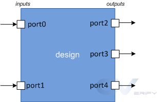
port
Ports are a set of signals that are used as inputs and outputs for specific modules and are the primary means of communicating with them.Think of a module as a prefabricated chip placed on a PCB. Obviously, the only way to communicate with the chip is through its pin.Ports are like pins that designers use to send and receive signals from the outside world.
port type
Port Description
- The input design module can only receive values from outside using its input port
- The output design module can only send values externally using its output port
- The inout design module can send or receive values using its inout port
By default, the port type is wire type.
grammar
  input  [net_type] [range] list_of_names;   // Input port
  inout  [net_type] [range] list_of_names;   // Input & Output port
  output [net_type] [range] list_of_names;   // Output port driven by a wire
  output [var_type] [range] list_of_names;   // Output port driven by a variable
For example:
module  my_design ( input wire      clk,
                    input           en,
                    input           rw,
                    inout [15:0]    data,
                    output           int );

  // Design behavior as Verilog code

endmodule
Note: Port names cannot be the same, as follows are not compliant:
  input  aport;         // First declaration - valid
  input  aport;         // Error - already declared
  output aport;         // Error - already declared
Signed Port Declaration
You can use the signed property to declare a signed port, which is unsigned by default.
 module (
           input signed a, b,  // a, b are signed from port declaration
           output reg signed c // c is signed from reg declaration
           );

  endmodule
References available:http://suo.im/5OkJ5D
Verilog 1995 vs. Verilog 2001
First look at how Verilog 1995 defines ports:
Verilog has undergone some modifications, and the original IEEE version of 1995 declared ports in the following manner.Ad locum,
The module declaration must first list the names of the ports in parentheses, then define the direction of these ports within the module body.
module test (a, b, c);

  input   [7:0] a;            // inputs "a" and "b" are wires
  input   [7:0] b;
  output   [7:0] c;       // output "c" by default is a wire

  // Still, you can declare them again as wires to avoid confusion
  wire   [7:0] a;
  wire   [7:0] b;
  wire   [7:0] c;
endmodule


module test (a, b, c);

  input  [7:0] a, b;
  output [7:0] c;           // By default c is of type wire

  // port "c" is changed to a reg type
  reg    [7:0] c;
endmodule
Verilog 2001 Revision:
The ANSI-C style port naming was introduced in 2001, allowing the type to be specified in the port list.
module test ( input [7:0]  a,
                            b,     // "b" is considered an 8-bit input
              output [7:0]  c);

  // Design content
endmodule

module test ( input wire [7:0]  a,
              input wire [7:0]  b,
              output reg [7:0]  c);

  // Design content
endmodule
If the port Declaration contains a network or variable type, the port is considered fully declared.It is illegal to redeclare the same port in a network or variable type declaration.
module test ( input      [7:0] a,       // a, e are implicitly declared of type wire
            output reg [7:0] e );

   wire signed [7:0] a;     // illegal - declaration of a is already complete -> simulator dependent
   wire        [7:0] e;     // illegal - declaration of e is already complete

   // Rest of the design code
endmodule
If the Port declaration does not contain a network or variable type, you can declare the port again in the network or variable type declaration.
module test ( input      [7:0] a,
              output     [7:0] e);

     reg [7:0] e;              // Okay - net_type was not declared before

     // Rest of the design code
endmodule
Reference material
Make a friend
-
Personal Wechat Public Number: GA LAB
-
KNOW: LI Ruiboun