1, UR robot pose representation
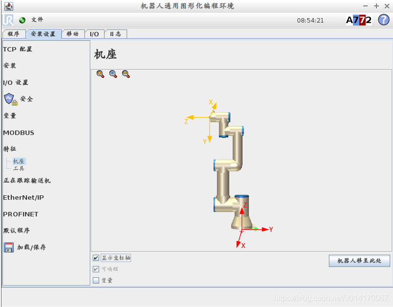
By default, the base coordinate system and TCP of UR robot are shown in the following figure:
Note that the TCP location and coordinate system here are in the default TCP configuration. The default TCP configuration is shown in the following figure:
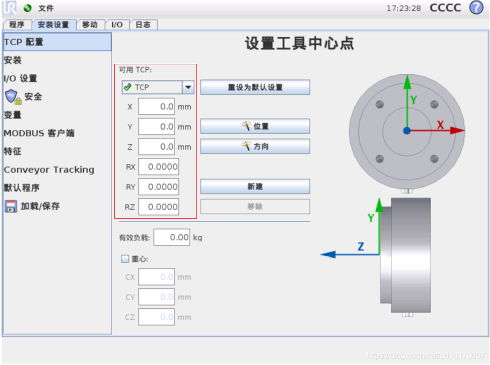
If the user wants to set the TCP position and coordinate system by himself, it can be configured on this basis. X,Y,Z, Rx, ry and RZ in the above figure represent the relationship between the user-defined TCP and the robot's default TCP (note that it is not relative to the base coordinate system). 10. Y and Z represent the position relationship. Rx, ry and RZ represent the attitude relationship expressed by the rotation vector method. See the next section for the rotation vector method.
After the UR robot returns to zero, the robot's default TCP pose relative to the base coordinate system is shown in the following figure:
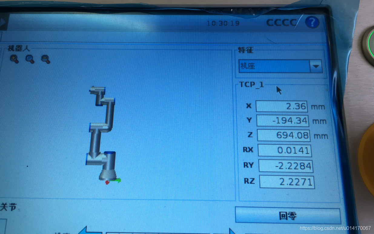
Note that this is the actual value. There are some errors compared with the theoretical value. For example, the theoretical value X=0, but the actual value may not be 0. The attitude description here uses the rotation vector method.
The Pose of UR robot represents the position and attitude of TCP coordinate system relative to base coordinate system. There are many ways to express the attitude of one coordinate system relative to another, such as X-Y-Z fixed angle, Z-Y-X Euler angle, RPY angle, quaternion, etc. The UR robot uses the rotation vector method.
Before introducing the rotation vector method, let's look at the representation of the equivalent axis angle coordinate system. The equivalent axis angle method is explained in detail in introduction to robotics, as shown in the figure below. This method uses a unit vector
And a rotation angle θ To represent the rotation relationship between the two coordinate systems. The details are shown in the figure below:
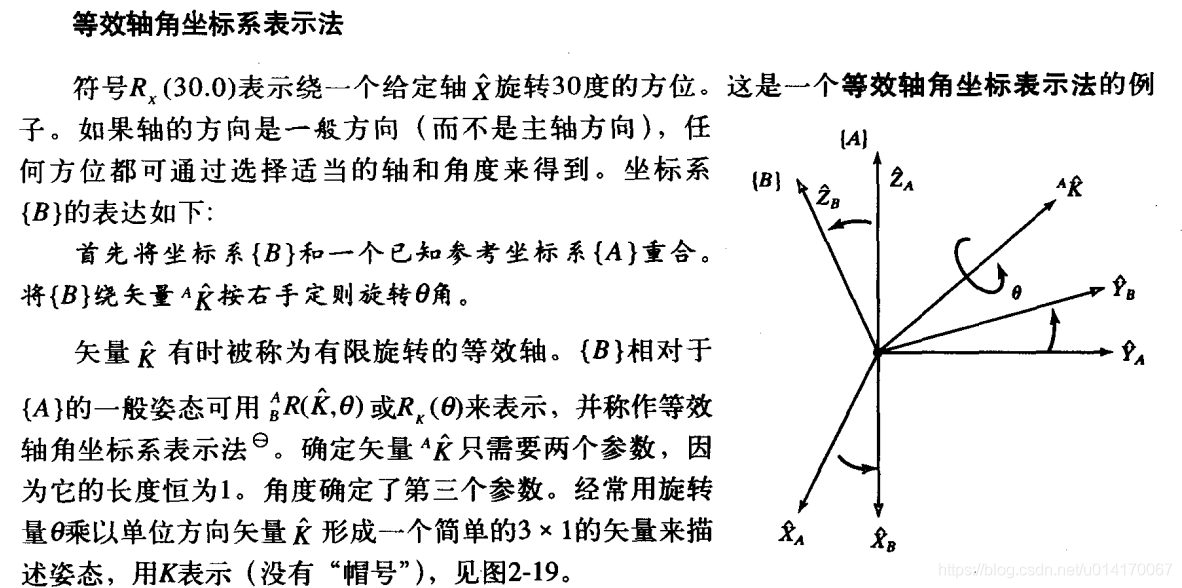
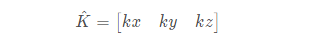
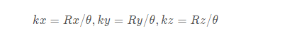
The rotation vector method uses a rotation vector:
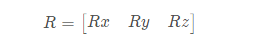
To represent the rotation relationship between the two coordinate systems, in which the relationship between the rotation vector method and the equivalent axis angle coordinate system is Rx= θ kx,Ry= θ ky,Rz= θ kz.
The rotation matrix can be obtained from the rotation vector according to the following formula:
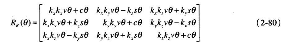
You need to find out before using the above formula θ And kx,ky,kz, the solution is as follows:
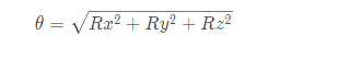
It can be seen that if θ= At 0 ° or 180 °, the rotation axis cannot be determined at all, and the above formula will have no solution. This is also an obvious disadvantage of the rotation vector method.
Conversely, if the rotation matrix is known, the equivalent axis angle representation can be solved by the following formula, and then the rotation vector representation can be obtained:
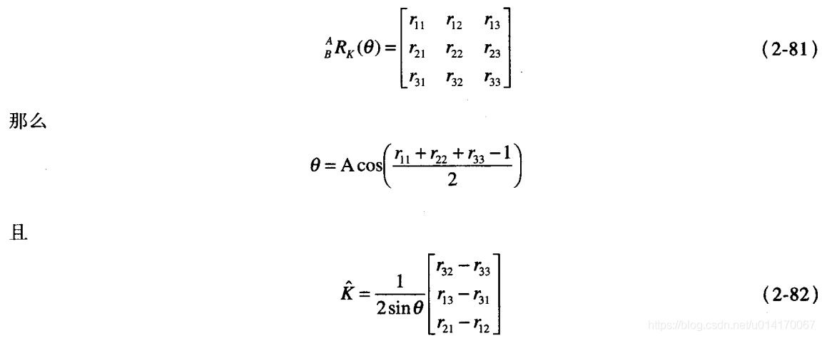
Note that r33 in 2-82 should be changed to r23, which is an error in the book.
As can be seen from the above description, the representation of rotation matrix is not unique for the same attitude. Therefore, in the UR robot, the TCP Pose observed through the panel may be different from the get through the script command_ actual_ tcp_ It is normal that the result of pose () is different. If you do not believe that they can be converted into RPY angles, you will find that they represent the same attitude.
2, UR robot hand eye calibration
Obtain the rotation relationship between the camera coordinate system and the robot TCP
3D coordinates in camera coordinate system
PW=T6TmPC
Then it becomes:
Pw*(T6^-1)=Tm*Pc
Obtain three-dimensional coordinate points under five camera coordinate systems and five robot coordinate systems,
And the pose (x,y,z,Rx,Ry,Rz) of the robot when collecting three-dimensional coordinate points in five camera coordinate systems
T6 matrix obtained from camera pose:
MATLAB program:
function [ Rt ] = URP2Rt( x, y, z, Rx, Ry, Rz )

theta = (Rx^2 + Ry^2 + Rz^2)^0.5;
kx = Rx/theta;
ky = Ry/theta;
kz = Rz/theta;
v = 1 - cos(theta);
s = sin(theta);
c = cos(theta);
R = [kx*kx*v + c, kx*ky*v - kz*s, kx*kz*v + ky*s;
    kx*ky*v + kz*s, ky*ky*v + c, ky*kz*v - kx*s;
    kx*kz*v - ky*s, ky*kz*v + kx*s, kz*kz*v + c;];
t = [x, y, z]';
Rt = [R t; 0 0 0 1];

end
C + + program:
Mat Cal_URT6(Mat T6, float Robot_postion[7])//Calculate T6 matrix
{
	float Px, Py, Pz, rota, rotb, rotc;
	Px = Robot_postion[1] * 1000;
	Py = Robot_postion[2] * 1000;
	Pz = Robot_postion[3] * 1000;

	rota = Robot_postion[4];
	rotb = Robot_postion[5];
	rotc = Robot_postion[6];

	float theta = sqrt(Robot_postion[4]*Robot_postion[4]+Robot_postion[5]*Robot_postion[5]+Robot_postion[6]*Robot_postion[6]);
    float kx = rota/theta;
	float ky = rotb/theta;
	float kz = rotc/theta;

	float v= 1-cos(theta);
	float s = sin(theta);
	float c = cos(theta);

	float m1[3][3]={kx*kx*v+c,kx*ky*v-kz*s,kx*kz*v+ky*s,kx*ky*v + kz*s, ky*ky*v + c, ky*kz*v - kx*s,kx*kz*v - ky*s, ky*kz*v + kx*s, kz*kz*v + c};
	Mat R1(3, 3, CV_32F, m1);

	float m4[3][1] = { Px, Py, Pz };
	Mat T1(3, 1, CV_32F, m4);

	float m5[1][4] = { 0, 0, 0, 1 };
	Mat T2(1, 4, CV_32F, m5);
	Mat A;
	hconcat(R1, T1, A);//A = [b c]
	vconcat(A, T2, T6);//A = [b;c]
	return T6;
}
Perform hand eye calibration
void Collectpoint1()
{
	Robot_postion[0] = 1 ;
	Robot_postion[1] = -0.08126;
	Robot_postion[2] = -0.40936;
	Robot_postion[3] = -0.62562;
	Robot_postion[4] = 5.067 ;
	Robot_postion[5] = -0.962;
	Robot_postion[6] = -3.564;
	float m1[3][1] = {-6.46543, 7.98035, 190.538};

	for (int i = 0; i < 3; i++)
	{
		for (int j = 0; j < 1; j++)
		{
			Ps1.at<float>(i, j) = m1[i][j];
		}
	}
	cout << "Ps1=" << Ps1 << endl;

	T61 = Cal_URT6(T6_robot, Robot_postion);
	//cout << "T61=" << T61<< endl;

	for (int i = 0; i < 4; i++)
	{
		for (int j = 0; j < 4; j++)
		{
			Ts1[i][j] = T61.at<float>(i, j);
			cout << Ts1[i][j] << ",";
		}
		cout << endl;
	}
}
void Get_Tm()
{
	cout << "Ts11=" << endl;
	for (int i = 0; i < 4; i++)
	{
		for (int j = 0; j < 4; j++)
		{
			cout << Ts1[i][j] << ",";
		}
		cout << endl;
	}
	cout << "Ts22=" << endl;
	for (int i = 0; i < 4; i++)
	{
		for (int j = 0; j < 4; j++)
		{
			cout << Ts2[i][j] << ",";
		}
		cout << endl;
	}
	cout << "Ts33=" << endl;
	for (int i = 0; i < 4; i++)
	{
		for (int j = 0; j < 4; j++)
		{
			cout << Ts3[i][j] << ",";
		}
		cout << endl;
	}
	cout << "Ts44=" << endl;
	for (int i = 0; i < 4; i++)
	{
		for (int j = 0; j < 4; j++)
		{
			cout << Ts4[i][j] << ",";
		}
		cout << endl;
	}
	cout << "Ts55=" << endl;
	for (int i = 0; i < 4; i++)
	{
		for (int j = 0; j < 4; j++)
		{
			cout << Ts5[i][j] << ",";
		}
		cout << endl;
	}


	float w1[1][4] = { -82.58,-401.29,-640.25,1 };
	Pw1 = Mat(4, 1, CV_32F, w1);
	cout << "Pw1=" << Pw1 << endl;

	float  w2[1][4] = { -82.58,-401.29,-640.25,1 };
	Pw2 = Mat(4, 1, CV_32F, w2);
	cout << "Pw2=" << Pw2 << endl;

	float  w3[1][4] = { -82.58,-401.29,-640.25,1 };
	Pw3 =Mat(4, 1, CV_32F, w3);
	cout << "Pw3=" << Pw3 << endl;

	float  w4[1][4] = { -82.58,-401.29,-640.25,1};
	Pw4 = Mat(4, 1, CV_32F, w4);
	cout << "Pw4=" << Pw4 << endl;

	float  w5[1][4] = { -82.58,-401.29,-640.25,1};
	Pw5 =Mat(4, 1, CV_32F, w5);
	cout << "Pw5=" << Pw5 << endl;

	//Mat TV_61(4, 4, CV_32F);
	//Mat TV_62(4, 4, CV_32F);
	//Mat TV_63(4, 4, CV_32F);
	//Mat TV_64(4, 4, CV_32F);
	//Mat TV_65(4, 4, CV_32F);

	for (int i = 0; i < 4; i++)
	{
		for (int j = 0; j < 4; j++)
		{
			T61.at<float>(i, j) = Ts1[i][j];
			T62.at<float>(i, j) = Ts2[i][j];
			T63.at<float>(i, j) = Ts3[i][j];
			T64.at<float>(i, j) = Ts4[i][j];
			T65.at<float>(i, j) = Ts5[i][j];
		}
	}
	T61 = Mat(4, 4, CV_32F, Ts1);
	T62 = Mat(4, 4, CV_32F, Ts2);
	T63 = Mat(4, 4, CV_32F, Ts3);
	T64 = Mat(4, 4, CV_32F, Ts4);
	T65 = Mat(4, 4, CV_32F, Ts5);

	cout << "T61=" << T61 << endl;
	cout << "T62=" << T62 << endl;
	cout << "T63=" << T63 << endl;
	cout << "T64=" << T64 << endl;
	cout << "T65=" << T65 << endl;

	invert(T61, TV_61, DECOMP_SVD);
	cout << "TV_61=" << TV_61 << endl;

	invert(T62, TV_62, DECOMP_SVD);
	cout << "TV_62=" << TV_62 << endl;

	invert(T63, TV_63, DECOMP_SVD);
	cout << "TV_63=" << TV_63 << endl;

	invert(T64, TV_64, DECOMP_SVD);
	cout << "TV_64=" << TV_64 << endl;

	invert(T65, TV_65, DECOMP_SVD);
	cout << "TV_65=" << TV_65 << endl;

	Pw11_1 = TV_61*Pw1;
	cout << "Pw11_1=" << Pw11_1 << endl;
	Pw22_2 = TV_62*Pw2;
	cout << "Pw22_2=" << Pw22_2 << endl;
	Pw33_3 = TV_63*Pw3;
	cout << "Pw33_3=" << Pw33_3 << endl;
	Pw44_4 = TV_64*Pw4;
	cout << "Pw44_4=" << Pw44_4 << endl;
	Pw55_5= TV_65*Pw5;
	cout << "Pw55_4=" << Pw55_5 << endl;


	Pw11_1(Rect(0, 0, 1, 3)).copyTo(Pw11);
	//cout << "Pw11=" << Pw11 << endl;
	Pw22_2(Rect(0, 0, 1, 3)).copyTo(Pw22);
	//cout << "Pw22=" << Pw22 << endl;
	Pw33_3(Rect(0, 0, 1, 3)).copyTo(Pw33);
	//cout << "Pw33=" << Pw33 << endl;
	Pw44_4(Rect(0, 0, 1, 3)).copyTo(Pw44);
	//cout << "Pw44=" << Pw44 << endl;
	Pw55_5(Rect(0, 0, 1, 3)).copyTo(Pw55);
	cout << "Pw55=" << Pw55 << endl;


	hconcat(Ps1, Ps2, A1);
	//cout << "A1=" << A1 << endl;
	hconcat(A1, Ps3, A2);
	//cout << "A2=" << A2 << endl;
	hconcat(A2, Ps4, A3);
	//cout << "A3=" << A3 << endl;
	hconcat(A3, Ps5, PS);
	cout << "PS=" << PS << endl;


	hconcat(Pw11, Pw22, B1);
	//cout << "B1=" << B1 << endl;
	hconcat(B1, Pw33, B2);
	//cout << "B2=" << B2 << endl;
	hconcat(B2, Pw44, B3);
	//cout << "B3=" << B3 << endl;
	hconcat(B3, Pw55, PW);
	cout << "PW=" << PW << endl;

	PS.copyTo(PSS);
	cout << "PSS=" << PSS << endl;

	PW.copyTo(PWW);
	cout << "PWW=" << PWW << endl;

	int row = PSS.rows;
	int col = PSS.cols;
	MatrixXd in(row, col);
	MatrixXd out(row, col);
	cv2eigen(PSS, in);
	cv2eigen(PWW, out);
	cout << "in=" << in << endl;
	cout << "out=" << out << endl;

	MatrixXd T;
	T = Eigen::umeyama(in, out, 0);//9ms
	cout << "Tm_Matrix = " << T << endl;
reference: https://blog.csdn.net/u014170067/article/details/83834043/