Improving diffuse reflection with texture
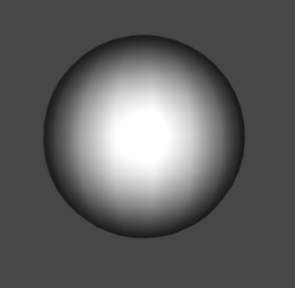
The effect of HalfLambert we did in the last article is as follows:
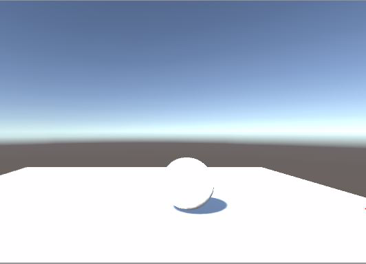
We can see that there is no natural transition from the bright part to the dark part, and the dark part is directly painted dark gray. Just like a sketch drawn by a beginner, the dark part is directly blackened without change.
This is because the lighting calculation is too simple. In real life, the dark part is not as dark as the picture because of diffuse reflection. But if we want to introduce lighting calculation, it is too complex. We can improve it with texture.
Because we need a texture map, first declare the texture in Properties:
_RampTex ("Ramp Texture", 2D) = "white"{}
Then declare a variable with the same name in CGPROGRAM:
sampler2D _RampTex;
Finally, just slightly change the HalfLambert lighting model:
// add this line
float3 ramp = tex2D(_RampTex, float2(hLambert,hLambert)).rgb;
......
// modify this line
col.rgb = s.Albedo * _LightColor0.rgb * ramp;
Assign the modified material to the ball and paste this map:

See the effect:
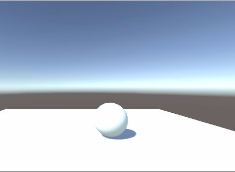
Is the light and shadow effect much more real?
This is because we map this map to the small ball according to the reflected light intensity, which changes the reflected color of the small ball.
Now let's do an experiment. Follow me:
Revise this sentence:
// float hLambert = 0.5 * difLight + 0.5;
float hLambert = difLight;
That is, do not use half Lambert light. Look at the results:
It's like this. Continue to revise this sentence:
float hLambert = 0.9 * difLight;
The map mapped on the ball moved a little, didn't it?
Then continue to modify, change 0.9 to 0.8, observe the effect, change 0.8 to 0.7, observe the effect, change 0.7 to 0.6, observe the effect
We see that the map moves up bit by bit. What do you find? In the process of reducing the value bit by bit, the value of the brightest point illuminated by the small ball slowly decreases from 1. Correspondingly, the brightest point gradually changes from white to blue gray. When the value is adjusted to 0.1, it becomes orange. For that map, the left side is yellow, the middle is blue gray, and the right side is blue white. If the texture is represented by coordinates, the left side should be 0, the middle is 0.5, and the right side is 1. So are you clear about the mapping relationship of the texture? When the value of the highlight of the ball is 0.5, it maps the central part of the map, which is blue gray. So you should know how this map is mapped on the ball to improve the light and shadow effect. After the improvement of half Lambert illumination, the place where the original illumination is 0 has become 0.5, so the middle part of the texture is mapped in a gradual blue gray, and the place where the original illumination is - 1 has become 0. The orange part on the left side of the texture is mapped. If you observe carefully, you can see that the color of the ball near the ground is yellowing, that is, the color on the left side of the texture.
People who have studied sketch know that the boundary between light and shade is the darkest. The backlight will be brighter because of reflection, so that the drawn shadow will not be dead black, but transparent and close to the truth. See the figure below:
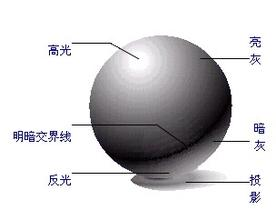
Therefore, the deepest color in the middle of the map is dark gray, which simulates the color at the junction of light and shade (that is, the place where the original illumination is 0 has been improved to 0.5), the gradient on the right simulates the color of the bright part, and the gradient on the left simulates the color of the dark part that becomes brighter due to reflection.
This effect still can't satisfy us, and the effect of shadow is not soft enough.
Fake BRDF
BRDF is short for bidirectional reflection distribution function, which means bidirectional reflection distribution function.
Before, we only considered the direction of incident light, so we can only get a linear result. In fact, a point on a surface has different effects due to different observation directions. Because of different angles, the intensity and color of light reflected into the eyes are different. So we're going to introduce a new variable, viewDir, which is the direction the human eye looks at the object. In other words, for the calculation of the color of a point on the surface, we should consider two directions, illumination direction and observation direction. It can be simply understood that the incident light is reflected in both the observation direction and the outgoing light on the opaque object surface.
OK, just go to the code and modify it sentence by sentence:
inline float4 LightingHalfLambert (SurfaceOutput s, fixed3 lightDir, half3 viewDir, fixed atten){
    float difLight = dot (s.Normal, lightDir);
    float rimLight = dot (s.Normal, viewDir);
    float dif_hLambert = 0.5 * difLight + 0.5;
    float rim_hLambert = 0.5 * rimLight + 0.5;
    float3 ramp = tex2D(_RampTex, float2(dif_hLambert, rim_hLambert)).rgb;

    float4 col;
    col.rgb = s.Albedo * _LightColor0.rgb * ramp;
    col.a = s.Albedo;
    return col;
}
In the lighting model function, we add a variable half3 viewDir, which is the observation direction. In the function, we define a new variable float rimLight, which is also the dot product of it and the normal direction, and then optimize it with HalfLambert. Finally, dif_hLambert and rim_hLambert is passed into the text2d function as uv coordinates.
Assign a new material to the ball and paste this map:
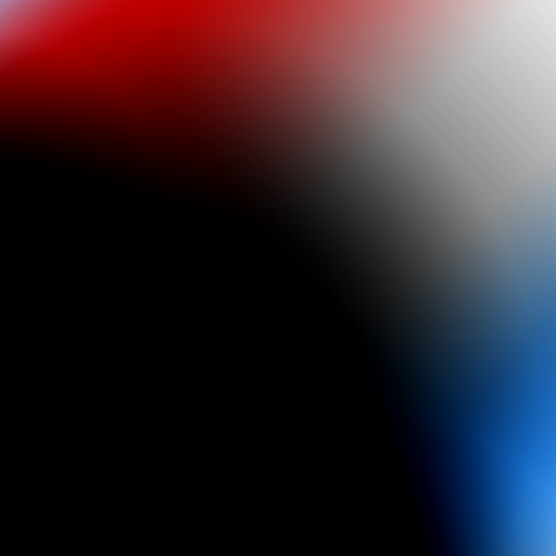
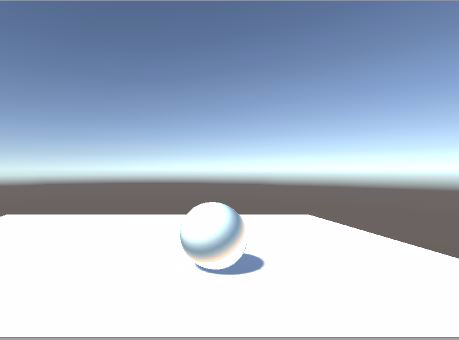
Let's see the effect:
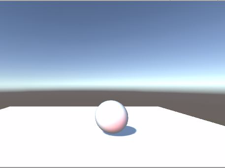
You can increase the value of the Slider, then give the ball a color, see the effect, and then compare it with the original material.
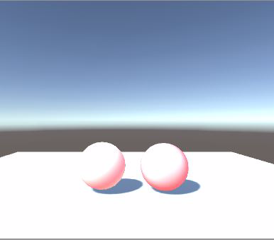
Look at the contrast. On the left is the last material that only considers the lighting direction, and on the right is the BRDF material. The left side simply distinguishes the bright side from the dark side. It seems that an arc is directly drawn to distinguish the light and dark boundary, while the light and dark transition on the right side is more gentle and varied.
Let's first analyze the mapping relationship of textures:
The lower left corner coordinates of the texture are (0, 0), the upper right corner coordinates are (1, 1), the upper left corner coordinates are (0, 1), and the lower right corner coordinates are (1, 0).
The lower left corner corresponds to the place where the light is weakest and farthest from people's line of sight, that is, the area where the ball is close to the ground, corresponding to the black texture; The upper right corner corresponds to the place with the strongest illumination and closest to people's line of sight, which is about the area near the highlight of the small ball and corresponds to the place with the whitest texture color; The upper left corner corresponds to the place with the weakest light but closest to the human line of sight, that is, the area with a little red in the effect picture without coloring; The lower right corner corresponds to the place with the strongest light but farthest from people's sight, that is, the edge area of the small ball close to the light source. We can see that it is a little blue in the picture without color.
In fact, the upper right corner to the lower left corner of the figure corresponds to the illumination direction, and the upper left corner to the lower right corner corresponds to the observation direction:
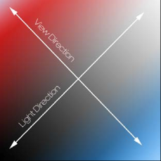
The results of the dot product of the observation direction and the plane normal vector are shown in the figure:
In other words, the closer you are to people's line of sight, the brighter it is, and the farther it is, the darker it is.
This is the same as the sketch. The shadow drawn by only considering the illumination direction is not three-dimensional, just like the previous shader. This is because only considering the volume of the illumination direction and the line of sight direction, the ball will have a more three-dimensional feeling.
The reason why we use a small ball to demonstrate the shader is that it is easier to see the relationship between light and shadow. The first lesson of sketch is to draw a ball.
In fact, shader and painting are indeed the same, except that one is to draw the desired result on paper with a pen, and the other is to "draw" the desired result with code
Attachment: Code List
Shader "Custom/RampDiffuse" {
    Properties {
        _EmissiveColor ("Emissive Color", Color) = (1,1,1,1)
        _AmbientColor ("Ambient Color", Color) = (1,1,1,1)
        _MySliderValue ("This is a Slider", Range(0,10)) = 2.5
        _RampTex ("Ramp Texture", 2D) = "white"{}
    }
    SubShader {
        Tags { "RenderType"="Opaque" }
        LOD 200

        CGPROGRAM
        // Physically based Standard lighting model, and enable shadows on all light types
        #pragma surface surf HalfLambert

        float4 _EmissiveColor;
        float4 _AmbientColor;
        float _MySliderValue;
        sampler2D _RampTex;

        struct Input {
            float2 uv_MainTex;
        };

        void surf (Input IN, inout SurfaceOutput o){
                float4 c;
                c = pow((_EmissiveColor + _AmbientColor), _MySliderValue);
                o.Albedo = c.rgb;
                o.Alpha = c.a;
        }

        inline float4 LightingHalfLambert (SurfaceOutput s, fixed3 lightDir, fixed atten){
            float difLight = dot (s.Normal, lightDir);
            float hLambert = 0.5 * difLight + 0.5;
            float3 ramp = tex2D(_RampTex, float2(hLambert,hLambert)).rgb;

            float4 col;
            col.rgb = s.Albedo * _LightColor0.rgb * ramp;
            col.a = s.Alpha;
            return col;
        }

        ENDCG
    }
    FallBack "Diffuse"
}