0. Preface
This tutorial is translated and adapted from TikZ official documents.
1. Establish environment
\documentclass[tikz,margin=10pt]{standalone}
\usetikzlibrary{calc}
\usetikzlibrary{backgrounds}
\usetikzlibrary{through} % In order to draw a circle more conveniently (the center of the circle and a point on the circle are known)
\usetikzlibrary{intersections}
\begin{document}
	\begin{tikzpicture}
		...
	\end{tikzpicture}
\end{document}
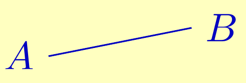
2. Straight line AB
Of course, we can use \ draw (0,0) - (2,0); Such code, but here A and B can actually be any two points. I just want to express the connection A and B. therefore, we can first define two points with the \ coordinate command.
\The coordinate command is an abbreviated version of the \ path coordinate command. If you don't want to name it, don't write at.
\coordinate (A)  at (0,0);
\coordinate (B) at (1.25,0.25);
\draw[blue] (A) -- (B);
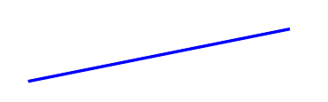
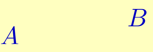
Now we add the annotation, which needs to be set when using the coordinate command, and it can be displayed without drawing a line. See the following example.
\coordinate[label=left:\textcolor{blue}{$ A $}] (A)  at (0,0);
\coordinate[label=right:\textcolor{blue}{$ B $}] (B) at (1.25,0.25);
Now draw the line.
\coordinate[label=left:\textcolor{blue}{$ A $}] (A)  at (0,0);
\coordinate[label=right:\textcolor{blue}{$ B $}] (B) at (1.25,0.25);
\draw[blue] (A) -- (B);
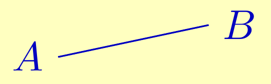
Now we want A and B to be really arbitrary, and TikZ just provides us with the rand function, which can produce A uniformly distributed random number between - 1 and 1 (while rnd produces A uniformly distributed random number between 0 and 1).
\coordinate[label=left:\textcolor{blue}{$ A $}] (A)  at (0+0.1*rand,0.1*rand);
\coordinate[label=right:\textcolor{blue}{$ B $}] (B) at (1.25+0.1*rand,0.25+0.1*rand);
\draw[blue] (A) -- (B);
This looks good, but we want to take the form of vector addition: ( 0 , 0 ) + 0.1 ( r a n d , r a n d ) (0,0)+0.1(\mathrm{rand},\mathrm{rand}) (0,0)+0.1(rand,rand), which requires the calc library.
\coordinate[label=left:\textcolor{blue}{$ A $}] (A)  at ($ (0,0) + 0.1*(rand,rand) $);
\coordinate[label=right:\textcolor{blue}{$ B $}] (B) at ($ (1.25,0.25) + 0.1*(rand,rand) $);
\draw[blue] (A) -- (B);
This syntax requires starting with ($and ending with $). Note that the dollar sign ($$) here does not represent the layout of mathematical formulas in the line, but indicates the operation.
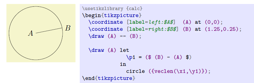
3. A circle centered on a
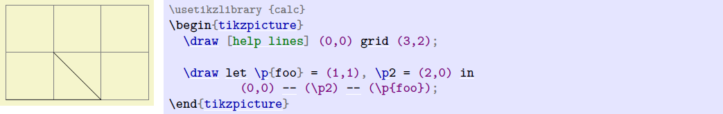
Drawing a circle is a little tricky because we don't want to calculate the length of AB manually. Therefore, we can use the let operation in TikZ.
let operation, syntax: \ path... let < assignment >, < assignment >, < assignment >... in;
In case of such a statement, < assignment > will be calculated in turn, and the calculation results will be temporarily stored in the register. We can then invoke the results through \ p \n \x \y these commands.
1) The first assignment statement has this form: \ n < number register > = {< formula >}< Number register > you can choose any name, such as English word phrase \ n{hello world} or number \ n3. If it is a letter, you should add curly braces. The calculation results are temporarily stored in < number register >, with units (e.g
p
t
,
c
m
\mathrm{pt,cm}
pt, cm) will retain units.
For example, if let \ N1 = {1pt + 2pt} \ N2 = < 1 + 2 > in... Then \ n1 \n2 will be expanded to
3
p
t
,
3
\mathrm{3pt,3}
3pt,3.
2) The second < assignment > has this form: \ P < point register > = {< formula >}. The point position register stores the position of a single point, including
p
t
\mathrm{pt}
pt metered
x
x
x coordinate sum
y
y
y coordinate.
 When \ P {< point register >} is written to the left of = it is only assigned; When it is written on the right or after in, it will be extended.
\X {< point register >} indicates the of the point
x
x
x coordinate, \ y {< point register >} represents the position of the point
y
y
y coordinate.
The macro described above is only applicable to let operations.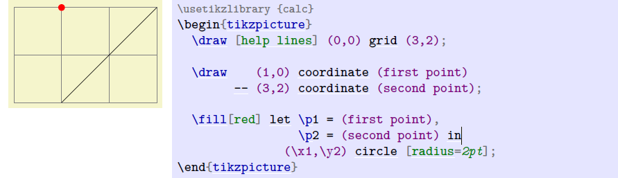
In the above example, you can also use the | - token:
\fill[red] let \p1 = (first point), \p2 = (second point) in (\p1|-\p2) circle [radius=2pt];
Note that the calculation result is only valid in the let in statement. If you want to use the calculation result outside the statement, you should use coordinate to keep it.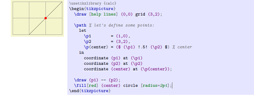
The exclamation mark representation is used here to represent the midpoint. I tried to add and divide by 2, and reported an error.
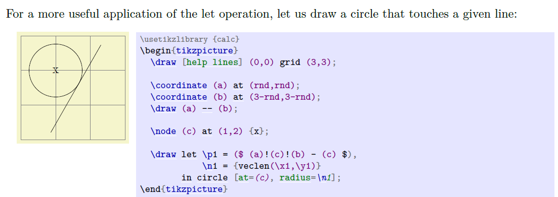
I can't understand the exclamation mark representation for this tangent circle.
The first layer of parentheses behind the circle is required by the circle command: (< center >) circle (< radius >), and the second layer of curly braces is to ensure that the veclen function is in the computing environment (remember {tan(30)} in the first section). If you add and subtract vectors allowed by calc or with exclamation marks, you should put them in ($$).
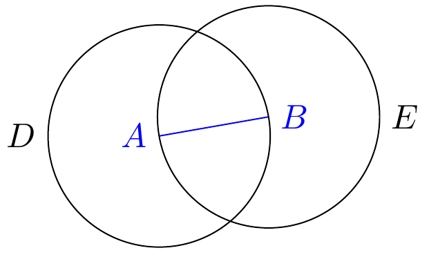
Now we want to draw two circles at once, so we can calculate the radius first, and then we don't have to calculate it again.
\coordinate[label=left:\textcolor{blue}{$ A $}] (A)  at ($ (0,0) + 0.1*(rnd,rand) $);
\coordinate[label=right:\textcolor{blue}{$ B $}] (B) at ($ (1.25,0.25) + 0.1*(rand,rand) $);
\draw[blue] (A) -- (B);
\draw let
	\p1 = ($ (B)-(A) $),
	\n2 = {veclen(\x1,\y1)}
	in (A) circle (\n2)
	   (B) circle (\n2);
In this code, if we call \ n1, it will not expand to any number, but will report an error because \ p \x \y is in the same namespace and \ n is in its own independent namespace.
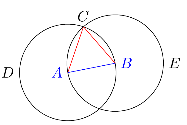
It is more convenient to draw A circle with TikZ's through library. Our idea is very simple. We know the center of the circle A, and the circle passes through B to make A circle, and through just realizes our idea.
\coordinate[label=left:\textcolor{blue}{$ A $}] (A)  at ($ (0,0) + 0.1*(rnd,rand) $);
\coordinate[label=right:\textcolor{blue}{$ B $}] (B) at ($ (1.25,0.25) + 0.1*(rand,rand) $);
\draw[blue] (A) -- (B);
\node[draw,circle through=(B),label=left:$ D $] at (A) {};
\node[draw,circle through=(A),label=right:$ E $] at (B) {};
The penultimate line of code works like this: first create A node without separation inside and outside, then set the node shape to A circle centered on A, and finally set the radius so that the circle just passes through point B.
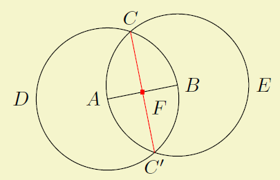
4. Intersection of circles
Now we need to find the intersection. Manual calculation is complicated. Fortunately, TikZ provides us with the intersection library, so that we can calculate the intersection of any path.
\coordinate[label=left:\textcolor{blue}{$ A $}] (A)  at ($ (0,0) + 0.1*(rnd,rand) $);
\coordinate[label=right:\textcolor{blue}{$ B $}] (B) at ($ (1.25,0.25) + 0.1*(rand,rand) $);
\draw[blue] (A) -- (B);
\node (D) [name path=D,draw,circle through=(B),label=left:$ D $] at (A) {};
\node (E) [name path=E,draw,circle through=(A),label=right:$ E $] at (B) {};
\path[name intersections={of=D and E,by={i1,i2}}];
\coordinate [label=above:$ C $] (C) at (i1);
\draw[red] (A)--(C);\draw[red] (B)--(C);
First, specify two path names as D and E (although they are the same as the node name, they do not affect each other because they are in different namespaces), and then make the intersection. Because there are two intersections, I use {i1,i2} to represent them (if I do not specify the intersection name by, it defaults to intersection-1, intersection-2...). I want to intersect the points above, so the last line is at (i1)
We can even mark the intersection by the way.
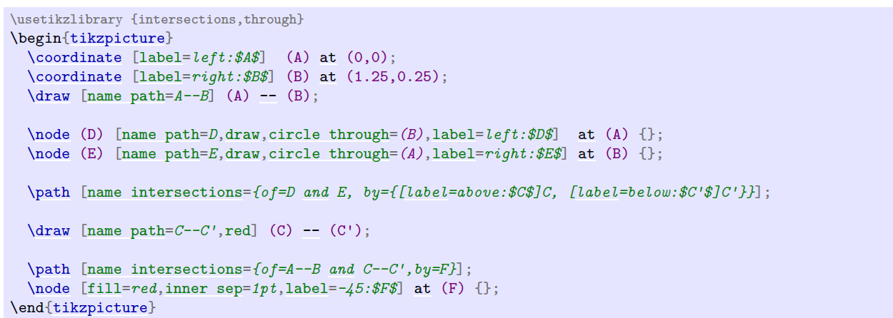
5. Complete code
\def\A{\textcolor{input}{$A$}} \def\B{\textcolor{input}{$B$}}
\def\C{\textcolor{output}{$C$}} \def\D{$D$}
\def\E{$E$}
\colorlet{input}{blue!80!black} \colorlet{output}{red!70!black}
\colorlet{triangle}{orange}
\coordinate [label=left:\A] (A) at ($ (0,0) + .1*(rand,rand) $);
\coordinate [label=right:\B] (B) at ($ (1.25,0.25) + .1*(rand,rand) $);
\draw [input] (A) -- (B);
\node [name path=D,help lines,draw,label=left:\D] (D) at (A) [circle through=(B)] {};
\node [name path=E,help lines,draw,label=right:\E] (E) at (B) [circle through=(A)] {};
\path [name intersections={of=D and E,by={[label=above:\C]C}}];
\draw [output] (A) -- (C) -- (B);
\foreach \point in {A,B,C}
\fill [black,opacity=.5] (\point) circle (2pt);
\begin{pgfonlayer}{background}
\fill[triangle!80] (A) -- (C) -- (B) -- cycle;
\end{pgfonlayer}
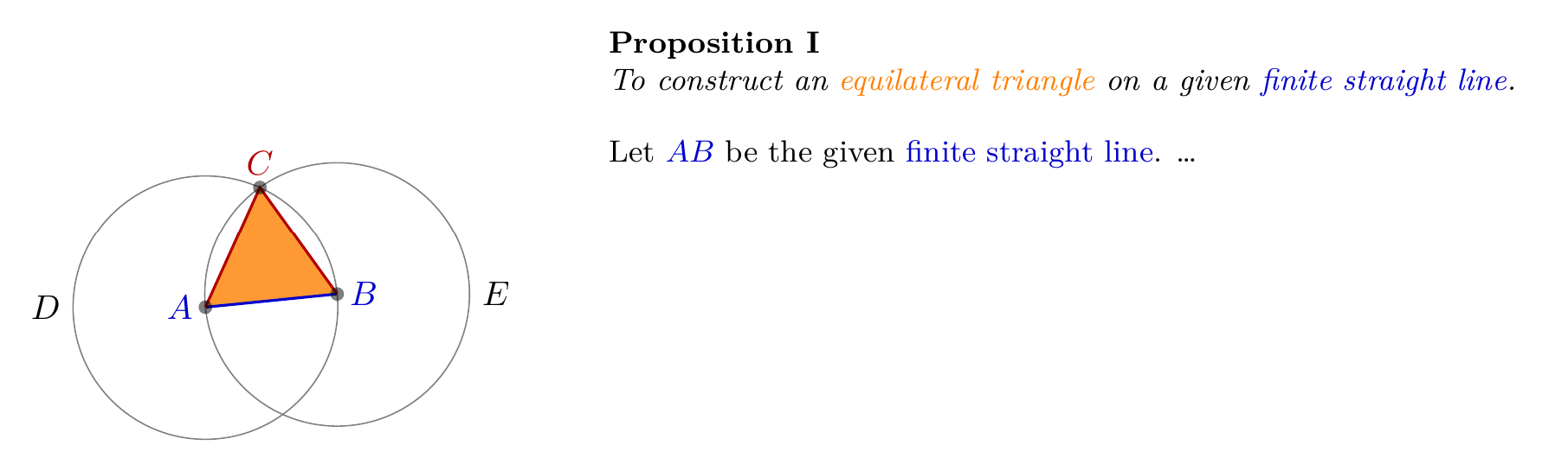
\node [below right, text width=10cm,align=justify] at (4,3) {
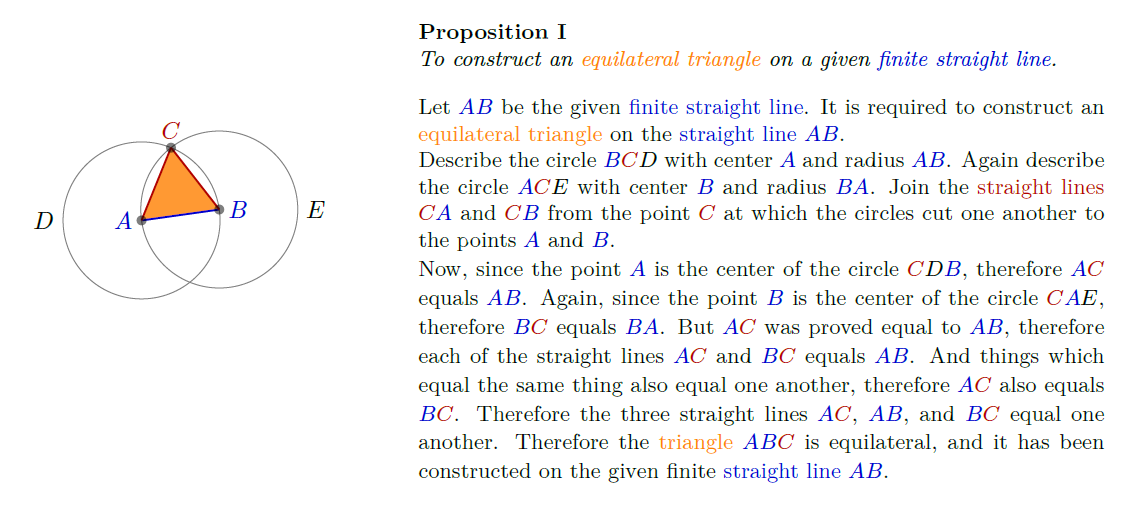
\small\textbf{Proposition I}\par
\emph{To construct an \textcolor{triangle}{equilateral triangle}
on a given \textcolor{input}{finite straight line}.}
\par\vskip1em
Let \A\B\ be the given \textcolor{input}{finite straight line}. \dots
};
Note: you can also use the \ begin{scope}[on background layer] \end{scope} code in the previous section to set the background. Here, the pgfonlayer environment is used, and the subsequent background is placed in curly brackets instead of square brackets.