Temperature alarm system based on FPGA (12864 display, audible and visual alarm)
preface
In this experiment, the DS18B20 is driven by FPGA to collect the temperature in real time and display it on the LCD screen 12864. At the same time, the specified temperature can be set by pressing the key. When the actual temperature is lower than the set temperature, the breathing lamp flashes normally, and the running water lamp lights up from left to right. When the actual temperature exceeds the set temperature, the buzzer sounds and the breathing lamp is always on. At the same time, the water lamp changes direction and turns on from right to left.
At the same time, the digital tube is also used to display the temperature in real time. (punctual atomic routine for comparison with the temperature I collected)
Finally, the experimental results are attached. Only part of the code is shown here.
Students who want a complete code can directly add my wechat: wxid_c82ezb72s7cf22 or QQ:1871478767.
1, DS18B20 temperature acquisition module
module ds18b20_ctrl(
//module clock
input clk , // Clock signal (50MHz)
input rst_n , // Reset signal
//user interface
inout dq , // DQ pin data of DS18B20
output reg [19:0] temp_data , // Temperature value obtained after conversion
output reg sign // Sign bit
);
//parameter define
localparam ROM_SKIP_CMD = 8'hcc; // Skip ROM command
localparam CONVERT_CMD = 8'h44; // Temperature conversion command
localparam READ_TEMP = 8'hbe; // Read DS1820 temperature register command
//state define
localparam init = 3'd1 ; // Initialization status
localparam rom_skip = 3'd2 ; // Load skip ROM command
localparam wr_byte = 3'd3 ; // Write byte status
localparam temp_convert = 3'd4 ; // Load temperature conversion command
localparam delay = 3'd5 ; // Delay waiting for the end of temperature conversion
localparam rd_temp = 3'd6 ; // Load read temperature command
localparam rd_byte = 3'd7 ; // Read byte status
//reg define
reg [ 4:0] cnt ; // Frequency division counter
reg clk_1us ; // 1MHz clock
reg [19:0] cnt_1us ; // Microsecond count
reg [ 2:0] cur_state ; // current state
reg [ 2:0] next_state ; // Next status
reg [ 3:0] flow_cnt ; // Flow count
reg [ 3:0] wr_cnt ; // Write count
reg [ 4:0] rd_cnt ; // Read count
reg [ 7:0] wr_data ; // Data written to DS18B20
reg [ 4:0] bit_width ; // Bit width of read data
reg [15:0] rd_data ; // Collected data
reg [15:0] org_data ; // Read raw temperature data
reg [10:0] data1 ; // Symbol processing of principle temperature
reg [ 3:0] cmd_cnt ; // Send command count
reg init_done ; // Initialization completion signal
reg st_done ; // Completion signal
reg cnt_1us_en ; // Enable timing
reg dq_out ; // dq output of DS18B20
//wire define
wire [19:0] data2 ; // Convert the processed
//*****************************************************
//** main code
//*****************************************************
assign dq = dq_out;
//Frequency division generates a 1MHz clock signal
always @ (posedge clk or negedge rst_n) begin
if (!rst_n) begin
cnt <= 5'b0;
clk_1us <= 1'b0;
end
else if(cnt < 5'd24) begin
cnt <= cnt + 1'b1;
clk_1us <= clk_1us;
end
else begin
cnt <= 5'b0;
clk_1us <= ~clk_1us;
end
end
//Microsecond timing
always @ (posedge clk_1us or negedge rst_n) begin
if (!rst_n)
cnt_1us <= 20'b0;
else if (cnt_1us_en)
cnt_1us <= cnt_1us + 1'b1;
else
cnt_1us <= 20'b0;
end
//state transition
always @ (posedge clk_1us or negedge rst_n) begin
if(!rst_n)
cur_state <= init;
else
cur_state <= next_state;
end
//Combinational logic state judgment transition condition
always @( * ) begin
case(cur_state)
init: begin // Initialization status
if (init_done)
next_state = rom_skip;
else
next_state = init;
end
rom_skip: begin // Load skip ROM command
if(st_done)
next_state = wr_byte;
else
next_state = rom_skip;
end
wr_byte: begin // dispatch orders
if(st_done)
case(cmd_cnt) // Judge the next status according to the command sequence number
4'b1: next_state = temp_convert;
4'd2: next_state = delay;
4'd3: next_state = rd_temp;
4'd4: next_state = rd_byte;
default:
next_state = temp_convert;
endcase
else
next_state = wr_byte;
end
temp_convert: begin // Load temperature conversion command
if(st_done)
next_state = wr_byte;
else
next_state = temp_convert;
end
delay: begin // Delay waiting for the end of temperature conversion
if(st_done)
next_state = init;
else
next_state = delay;
end
rd_temp: begin // Load read temperature command
if(st_done)
next_state = wr_byte;
else
next_state = rd_temp;
end
rd_byte: begin // Read data on data line
if(st_done)
next_state = init;
else
next_state = rd_byte;
end
default: next_state = init;
endcase
end
//The whole operation steps are initialization, sending skip ROM operation command, sending temperature conversion command
//Reinitialize, send skip ROM operation instructions, and send read data instructions.
always @ (posedge clk_1us or negedge rst_n) begin
if(!rst_n) begin
flow_cnt <= 4'b0;
init_done <= 1'b0;
cnt_1us_en <= 1'b1;
dq_out <= 1'bZ;
st_done <= 1'b0;
rd_data <= 16'b0;
rd_cnt <= 5'd0;
wr_cnt <= 4'd0;
cmd_cnt <= 3'd0;
end
else begin
st_done <= 1'b0;
case (next_state)
init:begin //initialization
init_done <= 1'b0;
case(flow_cnt)
4'd0:
flow_cnt <= flow_cnt + 1'b1;
4'd1: begin //Send 500us reset pulse
cnt_1us_en <= 1'b1;
if(cnt_1us < 20'd500)
dq_out <= 1'b0;
else begin
cnt_1us_en <= 1'b0;
dq_out <= 1'bz;
flow_cnt <= flow_cnt + 1'b1;
end
end
4'd2:begin //Release the bus and wait for 30us
cnt_1us_en <= 1'b1;
if(cnt_1us < 20'd30)
dq_out <= 1'bz;
else
flow_cnt <= flow_cnt + 1'b1;
end
4'd3: begin //Detection response signal
if(!dq)
flow_cnt <= flow_cnt + 1'b1;
else
flow_cnt <= flow_cnt;
end
4'd4: begin //Wait for initialization to complete
if(cnt_1us == 20'd500) begin
cnt_1us_en <= 1'b0;
init_done <= 1'b1; //Initialization complete
flow_cnt <= 4'd0;
end
else
flow_cnt <= flow_cnt;
end
default: flow_cnt <= 4'd0;
endcase
end
rom_skip: begin //Load skip ROM operation instruction
wr_data <= ROM_SKIP_CMD;
flow_cnt <= 4'd0;
st_done <= 1'b1;
end
wr_byte: begin //Write byte status (send instruction)
if(wr_cnt <= 4'd7) begin
case (flow_cnt)
4'd0: begin
dq_out <= 1'b0; //Pull down the data cable and start the write operation
cnt_1us_en <= 1'b1; //Start timer
flow_cnt <= flow_cnt + 1'b1;
end
4'd1: begin //Data cable pulled down 1us
flow_cnt <= flow_cnt + 1'b1;
end
4'd2: begin
if(cnt_1us < 20'd60) //send data
dq_out <= wr_data[wr_cnt];
else if(cnt_1us < 20'd63)
dq_out <= 1'bz; //Release bus (send interval)
else
flow_cnt <= flow_cnt + 1'b1;
end
4'd3: begin //Sending 1-bit data completed
flow_cnt <= 0;
cnt_1us_en <= 1'b0;
wr_cnt <= wr_cnt + 1'b1;//Write counter plus 1
end
default : flow_cnt <= 0;
endcase
end
else begin //End of sending command (1Byte)
st_done <= 1'b1;
wr_cnt <= 4'b0;
cmd_cnt <= (cmd_cnt == 3'd4) ? //Mark the sequence number of the currently sent instruction
3'd1 : (cmd_cnt+ 1'b1);
end
end
temp_convert: begin //Load temperature conversion command
wr_data <= CONVERT_CMD;
st_done <= 1'b1;
end
delay: begin //Wait for the temperature conversion to end after a delay of 500ms
cnt_1us_en <= 1'b1;
if(cnt_1us == 20'd500000) begin
st_done <= 1'b1;
cnt_1us_en <= 1'b0;
end
end
rd_temp: begin //Load read temperature command
wr_data <= READ_TEMP;
bit_width <= 5'd16; //Specifies the number of read data
st_done <= 1'b1;
end
rd_byte: begin //Receive 16 bit temperature data
if(rd_cnt < bit_width) begin
case(flow_cnt)
4'd0: begin
cnt_1us_en <= 1'b1;
dq_out <= 1'b0; //Pull down the data cable and start the read operation
flow_cnt <= flow_cnt + 1'b1;
end
4'd1: begin
dq_out <= 1'bz; //Release the bus and receive data within 15us
if(cnt_1us == 20'd14) begin
rd_data <= {dq,rd_data[15:1]};
flow_cnt <= flow_cnt + 1'b1 ;
end
end
4'd2: begin
if (cnt_1us <= 20'd64) //End of reading 1-bit data
dq_out <= 1'bz;
else begin
flow_cnt <= 4'd0;
rd_cnt <= rd_cnt + 1'b1;//Read counter plus 1
cnt_1us_en <= 1'b0;
end
end
default : flow_cnt <= 4'd0;
endcase
end
else begin
st_done <= 1'b1;
org_data <= rd_data;
rd_cnt <= 5'b0;
end
end
default: ;
endcase
end
end
//Judgment symbol bit
always @(posedge clk_1us or negedge rst_n) begin
if(!rst_n) begin
sign <= 1'b0;
data1 <= 11'b0;
end
else if(org_data[15] == 1'b0) begin
sign <= 1'b0;
data1 <= org_data[10:0];
end
else if(org_data[15] == 1'b1) begin
sign <= 1'b1;
data1 <= ~org_data[10:0] + 1'b1;
end
end
//Convert the collected temperature
assign data2 = (data1 * 11'd625)/ 7'd100;
//Temperature output
always @(posedge clk_1us or negedge rst_n) begin
if(!rst_n)
temp_data <= 20'b0;
else
temp_data <= data2;
end
endmodule
2, Nixie tube display module
module seg_led(
    input                   clk    ,        // clock signal
    input                   rst_n  ,        // Reset signal

    input         [19:0]    data   ,        // Value to be displayed by 6-digit nixie tube
    input         [5:0]     point  ,        // The specific display position of the decimal point, from high to low, and the high level is valid
    input                   en     ,        // Nixie tube enable signal
    input                   sign   ,        // Symbol bit (high level display "-")

    output   reg  [5:0]     seg_sel,        // The nixie tube position is selected, and the leftmost nixie tube is the highest position
    output   reg  [7:0]     seg_led         // Nixie tube segment selection
    );

//parameter define
localparam  CLK_DIVIDE = 4'd10     ;        // Clock divide factor
localparam  MAX_NUM    = 13'd5000  ;        // Count value required to count 1ms for nixie tube drive clock (5MHz)

//reg define
reg    [ 3:0]             clk_cnt  ;        // Clock division counter
reg                       dri_clk  ;        // Nixie tube drive clock, 5MHz
reg    [23:0]             num      ;        // 24 bit bcd code register
reg    [12:0]             cnt0     ;        // Nixie tube driven clock counter
reg                       flag     ;        // Flag signal (indicates that cnt0 count reaches 1ms)
reg    [2:0]              cnt_sel  ;        // Nixie tube position selection counter
reg    [3:0]              num_disp ;        // Data displayed by current nixie tube
reg                       dot_disp ;        // The decimal point displayed by the current nixie tube

//wire define
wire   [3:0]              data0    ;        // Single digit
wire   [3:0]              data1    ;        // Ten digits
wire   [3:0]              data2    ;        // Hundreds
wire   [3:0]              data3    ;        // thousands
wire   [3:0]              data4    ;        // Ten thousand digits
wire   [3:0]              data5    ;        // 100000 digits

//*****************************************************
//**                    main code
//*****************************************************

//Extract each bit of the decimal number corresponding to the displayed value
assign  data0 = data % 4'd10;               // Single digit
assign  data1 = data / 4'd10 % 4'd10   ;    // Ten digits
assign  data2 = data / 7'd100 % 4'd10  ;    // Hundreds
assign  data3 = data / 10'd1000 % 4'd10 ;   // thousands
assign  data4 = data / 14'd10000 % 4'd10;   // Ten thousand digits
assign  data5 = data / 17'd100000;          // 100000 digits

//Divide the system clock by 10 to obtain a nixie tube drive clock DRI with a frequency of 5MHz_ clk
always @(posedge clk or negedge rst_n) begin
   if(!rst_n) begin
       clk_cnt <= 4'd0;
       dri_clk <= 1'b1;
   end
   else if(clk_cnt == CLK_DIVIDE/2 - 1'd1) begin
       clk_cnt <= 4'd0;
       dri_clk <= ~dri_clk;
   end
   else begin
       clk_cnt <= clk_cnt + 1'b1;
       dri_clk <= dri_clk;
   end
end

//Convert a 20 bit binary number to 8421bcd code (i.e. use a 4-bit binary number to represent a 1-bit decimal number)
always @ (posedge dri_clk or negedge rst_n) begin
    if (!rst_n)
        num <= 24'b0;
    else begin
        if (data5 || point[5]) begin     //If the displayed data is a 6-digit decimal number,
            num[23:20] <= data5;         //Then assign values to the 6-bit nixie tube in turn
            num[19:16] <= data4;
            num[15:12] <= data3;
            num[11:8]  <= data2;
            num[ 7:4]  <= data1;
            num[ 3:0]  <= data0;
        end
        else begin
            if (data4 || point[4]) begin //If the displayed data is a 5-digit decimal number, assign a value to the lower 5-digit nixie tube
                num[19:0] <= {data4,data3,data2,data1,data0};
                if(sign)
                    num[23:20] <= 4'd11; //If a negative sign needs to be displayed, the highest bit (bit 6) is the sign bit
                else
                    num[23:20] <= 4'd10; //When a negative sign is not required, no character is displayed in bit 6
            end
            else begin                   //If the displayed data is a 4-digit decimal number, assign a value to the lower 4-digit nixie tube
                if (data3 || point[3]) begin
                    num[15: 0] <= {data3,data2,data1,data0};
                    num[23:20] <= 4'd10; //No characters are displayed in bit 6
                    if(sign)             //If a negative sign needs to be displayed, the highest bit (5th bit) is the sign bit
                        num[19:16] <= 4'd11;
                    else                 //When a negative sign is not required, no character is displayed in the fifth digit
                        num[19:16] <= 4'd10;
                end
                else begin               //If the display data is a 3-digit decimal number, assign a value to the lower 3-digit nixie tube
                    if (data2 || point[2]) begin
                        num[11: 0] <= {data2,data1,data0};
                                         //No characters are displayed in bits 6 and 5
                        num[23:16] <= {2{4'd10}};
                        if(sign)         //If a negative sign needs to be displayed, the highest bit (Bit 4) is the sign bit
                            num[15:12] <= 4'd11;
                        else             //When a negative sign is not required, no character is displayed in the fourth digit
                            num[15:12] <= 4'd10;
                    end
                    else begin           //If the display data is a 2-digit decimal number, assign a value to the lower 2-digit nixie tube
                        if (data1 || point[1]) begin
                            num[ 7: 0] <= {data1,data0};
                                         //No characters are displayed in bits 6, 5 and 4
                            num[23:12] <= {3{4'd10}};
                            if(sign)     //If a negative sign needs to be displayed, the highest bit (bit 3) is the sign bit
                                num[11:8]  <= 4'd11;
                            else         //When a negative sign is not required, no character is displayed in the third digit
                                num[11:8] <=  4'd10;
                        end
                        else begin       //If the display data is a 1-digit decimal number, assign a value to the lowest nixie tube
                            num[3:0] <= data0;
                                         //No characters are displayed in bits 6 and 5
                            num[23:8] <= {4{4'd10}};
                            if(sign)     //If a negative sign needs to be displayed, the highest bit (bit 2) is the sign bit
                                num[7:4] <= 4'd11;
                            else         //When a negative sign is not required, no character is displayed in the second digit
                                num[7:4] <= 4'd10;
                        end
                    end
                end
            end
        end
    end
end

//Whenever the counter counts the nixie tube drive clock for 1ms, it outputs a pulse signal of one clock cycle
always @ (posedge dri_clk or negedge rst_n) begin
    if (rst_n == 1'b0) begin
        cnt0 <= 13'b0;
        flag <= 1'b0;
     end
    else if (cnt0 < MAX_NUM - 1'b1) begin
        cnt0 <= cnt0 + 1'b1;
        flag <= 1'b0;
     end
    else begin
        cnt0 <= 13'b0;
        flag <= 1'b1;
     end
end

//cnt_sel counts from 0 to 5, which is used to select the nixie tube currently in the display state
always @ (posedge dri_clk or negedge rst_n) begin
    if (rst_n == 1'b0)
        cnt_sel <= 3'b0;
    else if(flag) begin
        if(cnt_sel < 3'd5)
            cnt_sel <= cnt_sel + 1'b1;
        else
            cnt_sel <= 3'b0;
    end
    else
        cnt_sel <= cnt_sel;
end

//Control the nixie tube position selection signal to make the 6-bit nixie tube display in turn
always @ (posedge dri_clk or negedge rst_n) begin
    if(!rst_n) begin
        seg_sel  <= 6'b111111;              //Bit select signal low level active
        num_disp <= 4'b0;
        dot_disp <= 1'b1;                   //Common anode nixie tube, low-level conduction
    end
    else begin
        if(en) begin
            case (cnt_sel)
                3'd0 :begin
                    seg_sel  <= 6'b111110;  //Display the lowest position of nixie tube
                    num_disp <= num[3:0] ;  //Displayed data
                    dot_disp <= ~point[0];  //Displayed decimal point
                end
                3'd1 :begin
                    seg_sel  <= 6'b111101;  //Display digit 1 of nixie tube
                    num_disp <= num[7:4] ;
                    dot_disp <= ~point[1];
                end
                3'd2 :begin
                    seg_sel  <= 6'b111011;  //Display digit 2 of nixie tube
                    num_disp <= num[11:8];
                    dot_disp <= ~point[2];
                end
                3'd3 :begin
                    seg_sel  <= 6'b110111;  //Display digit 3 of nixie tube
                    num_disp <= num[15:12];
                    dot_disp <= ~point[3];
                end
                3'd4 :begin
                    seg_sel  <= 6'b101111;  //Display digit 4 of nixie tube
                    num_disp <= num[19:16];
                    dot_disp <= ~point[4];
                end
                3'd5 :begin
                    seg_sel  <= 6'b011111;  //Display the highest position of nixie tube
                    num_disp <= num[23:20];
                    dot_disp <= ~point[5];
                end
                default :begin
                    seg_sel  <= 6'b111111;
                    num_disp <= 4'b0;
                    dot_disp <= 1'b1;
                end
            endcase
        end
        else begin
            seg_sel  <= 6'b111111;          //When the enable signal is 0, all nixie tubes do not display
            num_disp <= 4'b0;
            dot_disp <= 1'b1;
        end
    end
end

//Control the nixie tube segment selection signal and display characters
always @ (posedge dri_clk or negedge rst_n) begin
    if (!rst_n)
        seg_led <= 8'hc0;
    else begin
        case (num_disp)
            4'd0 : seg_led <= {dot_disp,7'b1000000}; //Display number 0
            4'd1 : seg_led <= {dot_disp,7'b1111001}; //Display number 1
            4'd2 : seg_led <= {dot_disp,7'b0100100}; //Display number 2
            4'd3 : seg_led <= {dot_disp,7'b0110000}; //Display number 3
            4'd4 : seg_led <= {dot_disp,7'b0011001}; //Display number 4
            4'd5 : seg_led <= {dot_disp,7'b0010010}; //Display number 5
            4'd6 : seg_led <= {dot_disp,7'b0000010}; //Display number 6
            4'd7 : seg_led <= {dot_disp,7'b1111000}; //Display number 7
            4'd8 : seg_led <= {dot_disp,7'b0000000}; //Display number 8
            4'd9 : seg_led <= {dot_disp,7'b0010000}; //Display number 9
            4'd10: seg_led <= 8'b11111111;           //No characters are displayed
            4'd11: seg_led <= 8'b10111111;           //Show negative sign (-)
            default:
                   seg_led <= {dot_disp,7'b1000000};
        endcase
    end
end

endmodule
3, Breathing lamp and water lamp module
module led_breath(
input clk,    //50MHz
input rst,

input en,
  output   reg    led1 ,
  output   reg    led2 ,
  output   reg    led3 ,

output reg led_o
);

//1s counter
reg flag_1s;
reg [28:0] cnt_1s;
always @(posedge clk)
begin
        if (! rst)begin
            cnt_1s <= 27'b0;
            flag_1s <= 1'b0;
        end
        else if(cnt_1s == 27'd49_999_999 ) begin
            cnt_1s <= 27'b0;
            flag_1s <= 1'b1;
        end
        else begin
            cnt_1s <= cnt_1s + 1'b1;
            flag_1s <= 1'b0;
        end
end

//1ms counter
reg flag_1ms;
reg [17:0] cnt_1ms;
always @(posedge clk)
begin
        if (! rst)begin
            cnt_1ms <= 18'b0;
            flag_1ms <= 1'b0;
        end
        else if(cnt_1ms == 18'd49_999 ) begin
            cnt_1ms <= 18'b0;
            flag_1ms <= 1'b1;
        end
        else begin
            cnt_1ms <= cnt_1ms + 1'b1;
            flag_1ms <= 1'b0;
        end
end

//1us counter
reg flag_1us;
reg [13:0] cnt_1us;
always @(posedge clk)
begin
        if (! rst)begin
            cnt_1us <= 7'b0;
            flag_1us <= 1'b0;
        end
        else if(cnt_1us == 7'd999) begin
            cnt_1us <= 7'b0;
            flag_1us <= 1'b1;
        end
        else begin
            cnt_1us <= cnt_1us + 1'b1;
            flag_1us <= 1'b0;
        end
end

//How many ms are counted
reg [9:0] number_ms;
always @(posedge clk)
begin
        if (! rst )begin
            number_ms <= 10'd0;
        end
        else begin
                if(number_ms == 10'd1000)begin
                    number_ms <= 10'd0;
                end
                else if(flag_1ms == 1'b1) begin
                    number_ms <= number_ms + 1'b1;
                end
                else begin
                    number_ms <= number_ms;
                end
        end
end


//How many us are counted
reg [9:0] number_us;
always @(posedge clk or negedge rst)
begin
        if (! rst )begin
            number_us <= 10'd0;
        end
        else begin
                if(number_us == 10'd1000)begin
                    number_us <= 10'd0;
                end
                else if(flag_1us == 1'b1) begin
                    number_us <= number_us + 1'b1;
                end
                else begin
                    number_us <= number_us;
                end
        end
end

//module of led breath
//
wire led_flag0; //From dark to bright
wire led_flag1; //From light to dark
assign  led_flag0 = (number_ms > number_us)? 1: 0;
assign  led_flag1 = (number_ms > number_us)? 0: 1;


reg led_flag;		//Flip the signal every 1s
always @(posedge clk or negedge rst)
begin
        if (! rst)begin
                led_flag <= 1'b1;
        end
        else if (flag_1s == 1'b1) begin
                led_flag <= ~ led_flag;
        end
        else begin
                led_flag <= led_flag;
        end

end

always @ (posedge clk or negedge rst) begin
	if(!rst)
	 led_o <= led_o;
	else if(en)
	 led_o <= 1'b1;
	else if(led_flag)
	 led_o <= led_flag0;
	else if(!led_flag)
    led_o <= led_flag1;
	else
	led_o <= led_o;
end


reg [2:0] state;//State machine

reg                clk_E;
reg     [30:0]     counter;


always@(posedge clk or negedge rst)   //frequency division
	begin
		if(!rst)
			begin
				counter<=0;
				clk_E<=0;
			end
		else
			begin
				if(counter == 5_000_000)begin
					clk_E <= ~clk_E;
                    counter<=0;
                end
				else
					begin
						counter  <= counter + 1'b1;
					end
			end
	end


always @ (posedge clk_E or negedge rst) begin
	if(!rst) begin
    led1  <= 1'b0   ;
    led2  <= 1'b0   ;
    led3  <= 1'b0   ;
	 state <= 3'd0;
            end
	else begin
		case(state)
			3'd0 : begin
			if(en == 1'b1)begin
	                    led1  <= 1'b0   ;
                       led2  <= 1'b0   ;
                       led3  <= 1'b1   ;
							 state <= state + 1;
							end
	             else begin
					        led1  <= 1'b1   ;
                       led2  <= 1'b0   ;
                       led3  <= 1'b0   ;
							  state <= state + 1;
							end
                  end
         3'd1 : begin
			if(en == 1'b1)begin
	                    led1  <= 1'b0   ;
                       led2  <= 1'b1   ;
                       led3  <= 1'b0   ;
							  state <= state + 1;
							end
	             else begin
					        led1  <= 1'b0   ;
                       led2  <= 1'b1   ;
                       led3  <= 1'b0   ;
							  state <= state + 1;
							end
						end
			3'd2 : begin
			if(en == 1'b1)begin
	                    led1  <= 1'b1   ;
                       led2  <= 1'b0   ;
                       led3  <= 1'b0   ;
							  state <= 3'd0;
							end
	             else begin
					        led1  <= 1'b0   ;
                       led2  <= 1'b0   ;
                       led3  <= 1'b1   ;
							  state <= 3'd0;
							end
						end
         endcase
end
end


endmodule
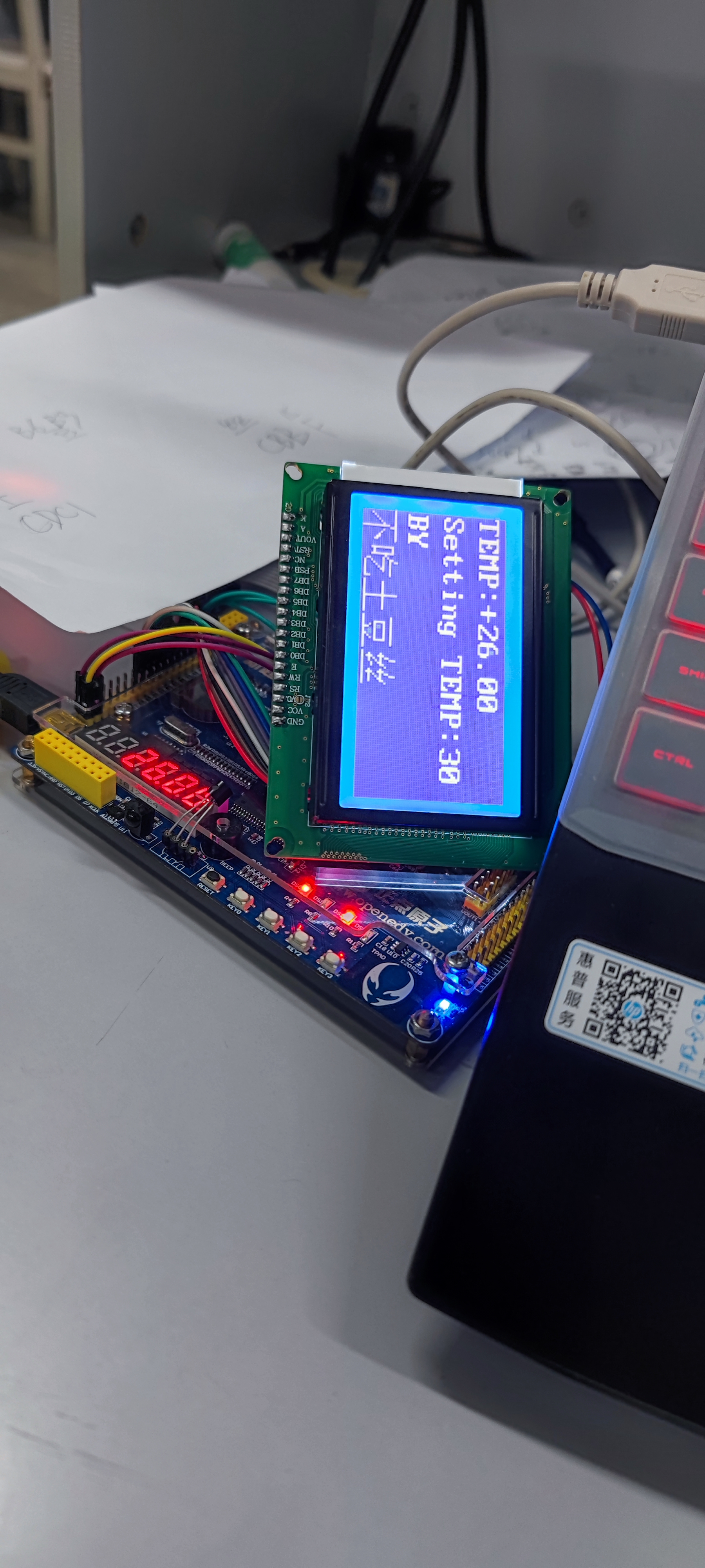
experimental result
Students who want a complete code can directly add my wechat: wxid_c82ezb72s7cf22 or QQ:1871478767.
summary
1: In this experiment, I encountered many problems. For example, when comparing values, the same type is required for comparison. For input, it is wire type, while output can be wire or register reg type. Here, a type conversion is required. For example
input  wire  a;
otput  reg   b;
reg c;
always @(posedge clk or negedge rst)
if(!rst)
    c  <=   a   ;
else
	 if(b > c);
	 .......
            end
Just like this, wire type can be converted to reg type for comparison. In the final analysis, the basic knowledge is not solid.
2: As for the display of words on the LCD screen, we provide a way for you. The word library in the online data manual is not easy to find the words you want. We recommend you to go to Taobao. Many businesses will attach their PDF documents of similar data manuals to the back of the goods. In it, we can directly find the words we want by Ctrl+F, This will be much faster than reading word by word in the font.
3: You must type more code and do it yourself. For example, I thought out the water lamp in my experiment above. At that time, when I looked at the water lamp routine, I didn't have much feeling. When I learned the state machine later, I suddenly had an idea, why can't the water lamp be written with the state machine? It is not necessary to use the method of bit splicing in the example. Although the method of state machine takes up more logical resources, it is quite successful to write it with your own ideas.
I hope you won't stop at the water lamp because of the introduction of the water lamp.
Finally, I hope you will praise and pay more attention. I only eat potato chips, not shredded potatoes.