System Verilog builds APB ﹣ I2C IP hierarchical verification platform
Keywords:
Verilog
Windows
Linux
simulator
Attribute
I. Preface
Recently, the epidemic is serious. As a social animal, I can only continue to study technology at home. I wrote a blog about building a FIFO verification platform before, using the OOP feature of SV to preliminarily verify FIFO, but there are many shortcomings, such as the structure is not standardized, the verification component class is not independent of DUT and so on. This attempt to verify more complex IP, and use more advanced features of SV to build a hierarchical verification platform.
2, APB? I2C IP overview
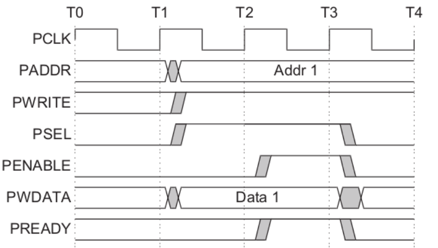
In order to practice the real knowledge, an APB ﹣ I2C IP core was downloaded from the opencores website, and the verification work was started. The first step is to understand the overall function, pin function and top-level structure of this IP. The overall function can be seen from the module name as I2C ﹐ master with APB bus interface. To understand the pin function and timing, directly cut off the schematic diagram on the SPEC to view:
APB_WRITE:
APB_READ:
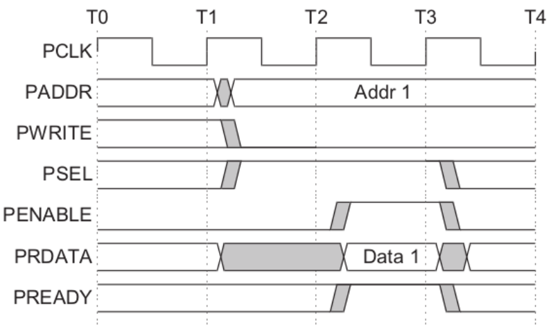
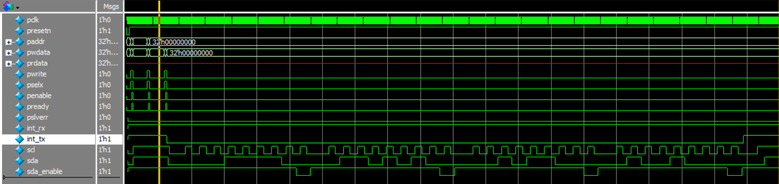
I2C_PROTOCOL:

Interface and protocol are not detailed here. Interested friends search for relevant information. As for the top structure, it's better to give it to the tools for convenience. But I didn't bring my virtual machine hard disk back home, so I had to download a WINDOW version of EDA tool. This paper uses QuestaSim, and the schematic diagram is as follows:
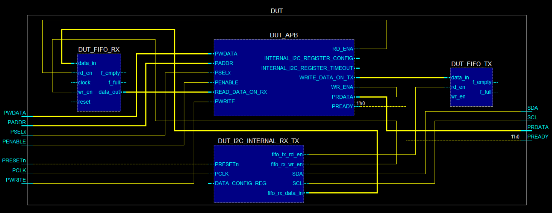
It is easy to see that the top layer of the module includes APB interface module, FIFO TX and FIFO RX used to cache data sent and received, and I2C protocol conversion module, i2x international RX TX. The master accesses the data buffer and configuration register inside the IP core through the APB bus, without paying attention to the internal implementation.
In addition to these aspects, configuration register access is also very important. The IP core must be properly configured and enabled to work as required. See the following table for configuration registers:
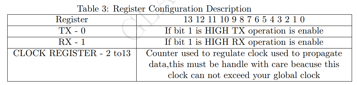
III. QuestaSim common instructions
The WINDOWS/LINUX version of QuestaSim tool is easy to download. The main difference between QuestaSim and Modelsim is that it supports SV UVM well, which is very in line with the intention of this article. However, it is very troublesome to click the mouse again and again in the simulation process, so we have to learn the operation command and write a script to cooperate with SV to realize automatic simulation. The following are the common instructions and explanations intercepted in the official documents user manual and tutorial.
1 Compile the source files.
vlog gates.v and2.v cache.v memory.v proc.v set.v top.v
2 Use the vopt command to optimize the design with full visibility into all design units
vopt +acc <design_name> -o <optimized_design_name> -debugdb
The +acc argument enables full visibility into the design for debugging purposes. The -oargument is required for naming the optimized design object. The -debugdb argument collects combinatorial and sequential logic data into the work library.
3 Use the optimized design name to load the design with the vsim command:
vsim testcounter_opt -debugdb
4 set WildcardFilter "Variable Constant Generic Parameter SpecParam Memory
Assertion Endpoint ImmediateAssert"
With this command, you remove "CellInternal" from the default list of Wildcard filters.
This allows all signals in cells to be logged by the simulator so they will be visible in the
debug environment.
5 Add Wave *
6 add log /*
This will provide the historic values of the events of interest plus its drivers
7 run 500
My do script file is also given:


 1 #quit -sim
 2
 3 set filename testbench
 4
 5 vlog *.v *.sv
 6
 7 vopt -debugdb +acc work.$filename -o top_opt1
 8 vsim -debugdb top_opt1
 9
10 #vsim -vopt -debugdb +acc work.$filename
11
12 # change WildcardFilter variables
13 set WildcardFilter "Variable Constant Generic Parameter SpecParam Memory Assertion Cover Endpoint ScVariable ImmediateAssert VHDLFile"
14
15 add wave /$filename/*
16 add log -r /*
17
18 run 1000ns
sim.do
IV. build verification environment
This section is the core of this article. The structure and components of the general verification environment are shown in the figure:
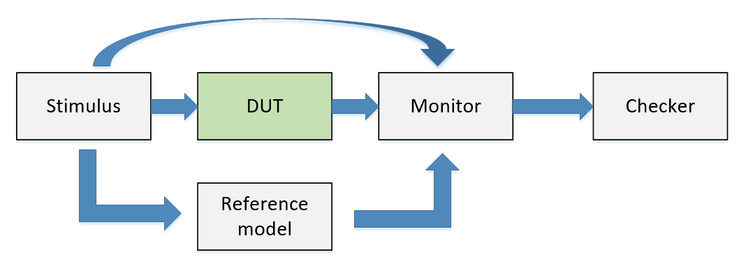
Stimulus will send the test excitation to DUT module to be tested, and Monitor will observe the response and send it to Checker. In case of complex design, Reference model should be designed to compare the response between actual response and golden reference. When the Monitor can not simply collect DUT response directly, it also needs to design VIP to analyze the complex response signal timing. In recent days, the basic verification environment is conceived according to the characteristics of APB ﹣ I2C module by referring to the reference books and online tutorial videos.
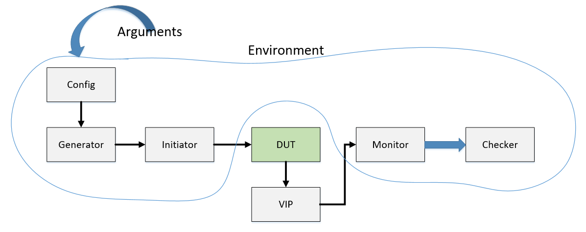
The APB I2C module is not complex, so it is not necessary to design a reference model. If you want to use the monitor component to get DUT response, you need to analyze the I2C protocol timing. Here, write a VIP to help it analyze the effective data, and then compare it with the Stimulus data. Monitor has been greatly simplified due to the existence of VIP. Its main function is to transmit data to Checker through MAILBOX for comparison after waiting for triggering event.
In addition, in order to separate Stimulus from specific interface signal operation, Generator and Initiator classes are established to generate read-write access and convert read-write access to specific signal logic corresponding to read-write operation. In order to realize "detail hiding" in OOP features, the configuration class Config is established to configure the verification Environment. Here, the main task is to configure the Generator to send read and write requests for specific scenarios. To test different functional features, just change the parameters passed in Config. This verification Environment includes five verification components of the Generator Initiator Monitor Checker Config. Here, the Environment class is established to package these components together for the convenience of calling methods. It's more intuitive (a little ugly, let's live)
In addition to verifying the environment structure, a good code structure can also greatly improve the reusability of the platform. Here, all classes and corresponding attribute methods are encapsulated in Package components, which is convenient to be import ed into testbench. All variable types and parameters used in the validation process are placed in definitions.sv.
Upper Code:
1 package components;
2 `include "defines.sv"
3
4 apb_bus_t apb_bus;
5 logic event_tx_i2c_vld,event_tx_vld;
6 data_t data_tx_i2c;
7 logic data_tx_i2c_vld;
8
9 //Driver
10 class Initiator;
11
12 function void init_en();
13 apb_bus.sel = 0;
14 apb_bus.wdata = 0;
15 apb_bus.addr = 0;
16 apb_bus.write = 0;
17 apb_bus.enable = 0;
18 endfunction
19
20 task write_oper(address_t address,data_t data_w);
21 @(posedge apb_bus.clk);
22 #1;
23 apb_bus.sel = 1;
24 apb_bus.write = 1;
25 apb_bus.wdata = data_w;
26 apb_bus.addr = address;
27 #T;
28 apb_bus.enable = 1;
29 #T;
30 init_en();
31 endtask
32
33 task read_oper(address_t address,output data_t data_r);
34 @(posedge apb_bus.clk);
35 #1;
36 apb_bus.sel = 1;
37 apb_bus.write = 0;
38 apb_bus.addr = address;
39 #T;
40 apb_bus.enable = 1;
41 #T;
42 data_r = apb_bus.rdata;
43 init_en();
44 endtask
45 endclass
46
47 typedef class Config;
48 //Generator
49 class Request;
50 data_t data_w;
51 data_t data_r;
52 Initiator initiator;
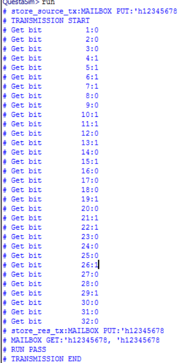
53
54 function new();
55 data_w = 32'h1234_5678;//32'b0001_0010_0011_0100_0101_0110_0111_1000
56 initiator = new();
57 clear_req();
58 endfunction
59
60 function void clear_req();
61 initiator.init_en();
62 endfunction
63
64 task configure_reg(data_t data_reg_config,data_t data_reg_timeout);
65 initiator.write_oper(ADDR_REG_CONFIG,data_reg_config);
66 #(T*10);
67 initiator.write_oper(ADD_REG_TIMEOUT,data_reg_timeout);
68 endtask
69
70 task write_data(data_t data_w);
71 initiator.write_oper(ADDR_TX_FIFO,data_w);
72 endtask
73
74 task read_data(output data_t data_r);
75 initiator.read_oper(ADDR_RX_FIFO,data_r);
76 endtask
77
78 task req_run(Config req_config);
79 if(req_config.config_type == CONFIG_WR_DATA)begin
80 configure_reg(data_t'({30'd10,WRI_EN}),data_t'(32'd10000));
81 write_data(data_w);
82 end
83 else if(req_config.config_type == CONFIG_RD_DATA)begin
84 configure_reg(data_t'({30'd10,RD_EN}),data_t'(32'd10000));
85 read_data(data_r);
86 end
87 endtask
88
89 endclass:Request
90
91 class Config;
92 config_type_t config_type;
93
94 function new(config_type_t config_type=CONFIG_RD_DATA);
95 this.config_type = config_type;
96 endfunction
97
98 endclass:Config
99
100 class Monitor;
101
102 mailbox #(data_t) mb_data_i2c_tx;
103 mailbox #(data_t) mb_data_tx;
104
105 function new(mailbox mb1,mailbox mb2);
106 this.mb_data_i2c_tx = mb1;
107 this.mb_data_tx = mb2;
108 endfunction
109
110 task store_res_tx();
111 wait(event_tx_i2c_vld);
112 #(T/2.0);
113 mb_data_i2c_tx.put(data_tx_i2c);
114 $display("store_res_tx:MAILBOX PUT:'h%h",data_tx_i2c);
115 endtask
116
117 task store_source_tx();
118 wait(event_tx_vld);
119 #(T/2.0);
120 mb_data_tx.put(apb_bus.wdata);
121 $display("store_source_tx:MAILBOX PUT:'h%h",apb_bus.wdata);
122 endtask
123
124 task mon_run();
125 fork
126 store_res_tx();
127 store_source_tx();
128 join
129 endtask
130
131 endclass:Monitor
132
133 class Checker;
134 uint cmp_cnt;
135 uint err_cnt;
136 data_t data_A,data_B;
137 mailbox #(data_t) mb_data_A,mb_data_B;
138 sim_res_t check_res;
139
140 function new(mailbox mb_A,mailbox mb_B);
141 cmp_cnt = 0;
142 err_cnt = 0;
143 this.mb_data_A = mb_A;
144 this.mb_data_B = mb_B;
145 endfunction
146
147 task collect_res();
148 mb_data_A.get(this.data_A);
149 mb_data_B.get(this.data_B);
150 $display("MAILBOX GET:'h%h, 'h%h",this.data_A,this.data_B);
151 endtask
152
153 function sim_res_t compare(data_t dataA,data_t dataB);
154 if(dataA == dataB)begin
155 check_res = TRUE;
156 end
157 else begin
158 err_cnt ++;
159 check_res = FALSE;
160 end
161 return check_res;
162 endfunction
163
164 task check_run();
165 sim_res_t check_res;
166 collect_res();
167 check_res = compare(data_A,data_B);
168 if(check_res == TRUE)
169 $display("RUN PASS");
170 else
171 $display("RUN FAIL");
172 endtask
173
174 endclass:Checker
175
176 class Environment;
177 mailbox #(data_t) mb[2];
178 Checker chk;
179 Request req;
180 Monitor monitor;
181 Config req_config;
182
183 function new();
184 uint i;
185 req_config = new();
186 req = new();
187 foreach(mb[i])
188 mb[i] = new();
189 monitor = new(mb[0],mb[1]);
190 chk = new(mb[0],mb[1]);
191 endfunction
192
193 task env_run();
194 fork
195 req.req_run(req_config);
196 monitor.mon_run();
197 join
198 chk.check_run();
199 endtask
200
201 endclass:Environment
202
203 endpackage
components.sv