preface
Theoretically, Tcl can complete all operations on Vivado, but it is not necessary. Because there are too many commands, it is difficult to remember. We only need to know a few commonly used commands to facilitate our use of Vivado.
For timing constraints, most of our commonly used tcl commands are clock related, because constraints are also clock constraints.
text
Here are some common operations and example effects (taking walegen, an engineering example of Xilinx, as an example). Let's have a look.
- report_clocks
Directly enter in the Tcl Console box:
report_clocks
The constraints on the clock in the project can be displayed.
However, the premise is that the authorized design or Synthesized Design or implemented Design is opened.
If one of the three is not open, you will be prompted:
ERROR: [Common 17-53] User Exception: No open design.
Please open an elaborated, synthesized or implemented design before executing this command.
For example, after I open the edited design, enter this command:
Clock Report


Attributes
  P: Propagated
  G: Generated
  A: Auto-derived
  R: Renamed
  V: Virtual
  I: Inverted
  S: Pin phase-shifted with Latency mode

Clock              Period(ns)  Waveform(ns)    Attributes  Sources
clk_pin_p          5.000       {0.000 2.500}   P           {clk_pin_p}
virtual_clock      6.000       {0.000 3.000}   V           {}
clk_samp           192.000     {0.000 96.000}  P,G         {clk_gen_i0/BUFHCE_clk_samp_i0/O}
spi_clk            6.000       {3.000 6.000}   P,G,I       {spi_clk_pin}
clk_rx_clk_core    5.000       {0.000 2.500}   P,G,A       {clk_gen_i0/clk_core_i0/inst/mmcm_adv_inst/CLKOUT0}
clk_tx_clk_core    6.000       {0.000 3.000}   P,G,A       {clk_gen_i0/clk_core_i0/inst/mmcm_adv_inst/CLKOUT1}
clkfbout_clk_core  5.000       {0.000 2.500}   P,G,A       {clk_gen_i0/clk_core_i0/inst/mmcm_adv_inst/CLKFBOUT}


====================================================
Generated Clocks
====================================================

Generated Clock     : clk_samp
Master Source       : clk_gen_i0/clk_core_i0/clk_tx
Master Clock        : clk_tx_clk_core
Divide By           : 32
Generated Sources   : {clk_gen_i0/BUFHCE_clk_samp_i0/O}

Generated Clock     : spi_clk
Master Source       : dac_spi_i0/out_ddr_flop_spi_clk_i0/ODDR_inst/C
Master Clock        : clk_tx_clk_core
Divide By           : 1
Generated Sources   : {spi_clk_pin}

Generated Clock     : clk_rx_clk_core
Master Source       : clk_gen_i0/clk_core_i0/inst/mmcm_adv_inst/CLKIN1
Master Clock        : clk_pin_p
Multiply By         : 1
Generated Sources   : {clk_gen_i0/clk_core_i0/inst/mmcm_adv_inst/CLKOUT0}

Generated Clock     : clk_tx_clk_core
Master Source       : clk_gen_i0/clk_core_i0/inst/mmcm_adv_inst/CLKIN1
Master Clock        : clk_pin_p
Edges               : {1 2 3}
Edge Shifts(ns)     : {0.000 0.500 1.000}
Generated Sources   : {clk_gen_i0/clk_core_i0/inst/mmcm_adv_inst/CLKOUT1}

Generated Clock     : clkfbout_clk_core
Master Source       : clk_gen_i0/clk_core_i0/inst/mmcm_adv_inst/CLKIN1
Master Clock        : clk_pin_p
Multiply By         : 1
Generated Sources   : {clk_gen_i0/clk_core_i0/inst/mmcm_adv_inst/CLKFBOUT}


====================================================
User Uncertainty
====================================================


====================================================
User Jitter
====================================================
The properties of the clock are also at a glance. We notice the three clocks:
clk_rx_clk_core    5.000       {0.000 2.500}   P,G,A       {clk_gen_i0/clk_core_i0/inst/mmcm_adv_inst/CLKOUT0}
clk_tx_clk_core    6.000       {0.000 3.000}   P,G,A       {clk_gen_i0/clk_core_i0/inst/mmcm_adv_inst/CLKOUT1}
clkfbout_clk_core  5.000       {0.000 2.500}   P,G,A       {clk_gen_i0/clk_core_i0/inst/mmcm_adv_inst/CLKFBOUT}
Its clock attributes include A, that is, the automatically generated clock, that is, these clocks are not the clocks that we manually constrain in the Xdc file, but the clocks that are automatically constrained by the IP core according to user-defined settings.
For the master clock passing through the clock IP, the constraint only needs to constrain the input, and the output clock IP will be inferred automatically. Sometimes (maybe a higher version of Vivado tool), the input clock is automatically constrained for you. If you constrain it again, there will be a warning? In the face of this situation, it's OK to restrict or not. Depending on your personal habits, you don't have to pay attention to this warning.
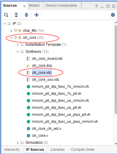
As for why there is one more clkfbuf_clk_core, look at the IP. We didn't generate such a clock.
Well, if you know about IP, you will know that this is a feedback clock automatically generated by IP.
We also note that for the constraint of differential input clock:
clk_pin_p 5.000 {0.000 2.500} P {clk_pin_p}
Just constrain the P-end.
This is allowed and recommended. It is not necessary to restrict both PN and differential clock.
- report_clock_networks
This tcl command is mainly used to check whether there are forgotten master clock constraints. If not, for example, our wavegen project:
report_clock_networks

------------------------------------------------------------------------------------
| Tool Version : Vivado v.2019.1 (win64) Build 2552052 Fri May 24 14:49:42 MDT 2019
| Date         : Thu Oct  7 22:45:10 2021
| Host         : DESKTOP-REBORN running 64-bit major release  (build 9200)
| Command      : report_clock_networks
| Design       : wave_gen
| Device       : 7k70t-fbg676
| Speed File   : -1  PRODUCTION 1.12 2017-02-17
------------------------------------------------------------------------------------

Clock Networks Report


Constrained Clocks
-------------------

Clock clk_pin_p (200MHz)(endpoints: 645 clock, 1 nonclock)
Port clk_pin_p

Clock virtual_clock (166.667MHz)(endpoints: 0 clock, 0 nonclock)
If we comment out the master clock constraint in the constraint file, note that the master clock of the wavegen project is in the XDC file of the IP:
Note out:

After integration, run this command:
Clock Networks Report


Constrained Clocks
-------------------

Clock virtual_clock (166.667MHz)(endpoints: 0 clock, 0 nonclock)


Unconstrained Clocks
-------------------

Clock clk_pin_p (endpoints: 645 clock, 1 nonclock)
Port clk_pin_p
Visible, a prompt will appear that the master clock is not constrained.
As long as it prompts, try to give constraints.
Note: if you want to display clock networks on the GUI interface, you can enter the command:
report_clock_networks -name mainclock
You can see the clock information more intuitively.
- check_timing
This command can check the changed content. We try to enter it in wavegen, and you can get:
check_timing report

Table of Contents
-----------------
1. checking no_clock
2. checking constant_clock
3. checking pulse_width_clock
4. checking unconstrained_internal_endpoints
5. checking no_input_delay
6. checking no_output_delay
7. checking multiple_clock
8. checking generated_clocks
9. checking loops
10. checking partial_input_delay
11. checking partial_output_delay
12. checking latch_loops

1. checking no_clock
--------------------
 There are 0 register/latch pins with no clock.


2. checking constant_clock
--------------------------
 There are 0 register/latch pins with constant_clock.


3. checking pulse_width_clock
-----------------------------
 There are 0 register/latch pins which need pulse_width check


4. checking unconstrained_internal_endpoints
--------------------------------------------
 There are 0 pins that are not constrained for maximum delay.

 There are 0 pins that are not constrained for maximum delay due to constant clock.


5. checking no_input_delay
--------------------------
 There are 0 input ports with no input delay specified.

 There is 1 input port with no input delay but user has a false path constraint. (MEDIUM)


6. checking no_output_delay
---------------------------
 There are 0 ports with no output delay specified.

 There are 0 ports with no output delay but user has a false path constraint

 There is 1 port with no output delay but with a timing clock defined on it or propagating through it (LOW)


7. checking multiple_clock
--------------------------
 There are 0 register/latch pins with multiple clocks.


8. checking generated_clocks
----------------------------
 There are 0 generated clocks that are not connected to a clock source.


9. checking loops
-----------------
 There are 0 combinational loops in the design.


10. checking partial_input_delay
--------------------------------
 There are 0 input ports with partial input delay specified.


11. checking partial_output_delay
---------------------------------
 There are 0 ports with partial output delay specified.


12. checking latch_loops
------------------------
 There are 0 combinational latch loops in the design through latch input
It can be seen that there are many inspection contents:
1. checking no_clock
2. checking constant_clock
3. checking pulse_width_clock
4. checking unconstrained_internal_endpoints
5. checking no_input_delay
6. checking no_output_delay
7. checking multiple_clock
8. checking generated_clocks
9. checking loops
10. checking partial_input_delay
11. checking partial_output_delay
12. checking latch_loops
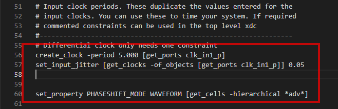
To try the effect, we also comment out the master clock constraint:
# Differential clock only needs one constraint
#create_clock -period 5.000 [get_ports clk_in1_p]
#set_input_jitter [get_clocks -of_objects [get_ports clk_in1_p]] 0.05


#set_property PHASESHIFT_MODE WAVEFORM [get_cells -hierarchical *adv*]
Then enter check_timing :
check_timing report

Table of Contents
-----------------
1. checking no_clock
2. checking constant_clock
3. checking pulse_width_clock
4. checking unconstrained_internal_endpoints
5. checking no_input_delay
6. checking no_output_delay
7. checking multiple_clock
8. checking generated_clocks
9. checking loops
10. checking partial_input_delay
11. checking partial_output_delay
12. checking latch_loops

1. checking no_clock
--------------------
 There are 604 register/latch pins with no clock driven by root clock pin: clk_pin_p (HIGH)

 There are 41 register/latch pins with no clock driven by root clock pin: clk_gen_i0/BUFHCE_clk_samp_i0/O (HIGH)


2. checking constant_clock
--------------------------
 There are 0 register/latch pins with constant_clock.


3. checking pulse_width_clock
-----------------------------
 There are 0 register/latch pins which need pulse_width check


4. checking unconstrained_internal_endpoints
--------------------------------------------
 There are 1468 pins that are not constrained for maximum delay. (HIGH)

 There are 0 pins that are not constrained for maximum delay due to constant clock.


5. checking no_input_delay
--------------------------
 There is 1 input port with no input delay specified. (HIGH)

 There is 1 input port with no input delay but user has a false path constraint. (MEDIUM)


6. checking no_output_delay
---------------------------
 There are 0 ports with no output delay specified.

 There are 0 ports with no output delay but user has a false path constraint

 There is 1 port with no output delay but with a timing clock defined on it or propagating through it (LOW)


7. checking multiple_clock
--------------------------
 There are 0 register/latch pins with multiple clocks.


8. checking generated_clocks
----------------------------
 There are 2 generated clocks that are not connected to a clock source. (HIGH)


9. checking loops
-----------------
 There are 0 combinational loops in the design.


10. checking partial_input_delay
--------------------------------
 There are 0 input ports with partial input delay specified.


11. checking partial_output_delay
---------------------------------
 There are 0 ports with partial output delay specified.


12. checking latch_loops
------------------------
 There are 0 combinational latch loops in the design through latch input
It can be seen that the missing clock is also reported:
1. checking no_clock
--------------------
 There are 604 register/latch pins with no clock driven by root clock pin: clk_pin_p (HIGH)

 There are 41 register/latch pins with no clock driven by root clock pin: clk_gen_i0/BUFHCE_clk_samp_i0/O (HIGH)
For special inspection: checking no_clock
You can enter commands for:
check_timing -override_defaults no_clock
Available:
check_timing report

Table of Contents
-----------------
1. checking no_clock

1. checking no_clock
--------------------
 There are 604 register/latch pins with no clock driven by root clock pin: clk_pin_p (HIGH)

 There are 41 register/latch pins with no clock driven by root clock pin: clk_gen_i0/BUFHCE_clk_samp_i0/O (HIGH)
Straight forward.
That's all for this short article.