This paper introduces the RT thread real-time operating system running on hummingbird processor and the development of ESP8266 wifi module.
Transplantation of RT thread is provided in the supporting sdk of hummingbird https://github.com/riscv-mcu/hbird-sdk/tree/0.1.2/application/rtthread/msh , we only need to carry out specific application development on its basis, which greatly reduces the workload of users. We choose to develop on the basis of the official msh application, because it contains the fish component in RT thread, which can make users and programs interact well.
RT thread learning can refer to the following connections:
Old document center https://www.rt-thread.org/document/site/
New document center https://docs.rt-thread.org/#/
The video tutorial released by RT thread's official account on station B https://www.bilibili.com/video/BV1of4y1S7Ju/?spm_id_from=333.788.recommend_more_video.0
ESP8266 wifi module can realize wireless communication. Compared with network port transmission, it is more portable, more powerful and more convenient to develop. The way based on serial port control determines that it is suitable for the situation of small data transmission and low communication rate requirements. It is often used in low-power Internet of things system. The ESP8266 module is developed through the customized AT instruction set and supports three working modes: STA/AP/STA+AP, which will not be expanded.
We chose the products of anxinco technology ESP-01S module , for the use of the basic AT set, you do not need to burn the firmware yourself, and you can use it out of the box. When you get the ESP-01S module, you can first connect to the computer through the USB-TTL transfer interface for testing. For AT instruction set and test method, please refer to the tutorial officially released by RT thread https://www.bilibili.com/video/BV1of4y1S7Ju?p=18.
After the test, connect it to the development board. The typical connection method is as follows (picture from https://www.bilibili.com/video/BV1of4y1S7Ju?p=18 ). In our application, the pins of ESP-01S are connected to the PMOD interface of FPGA development board.
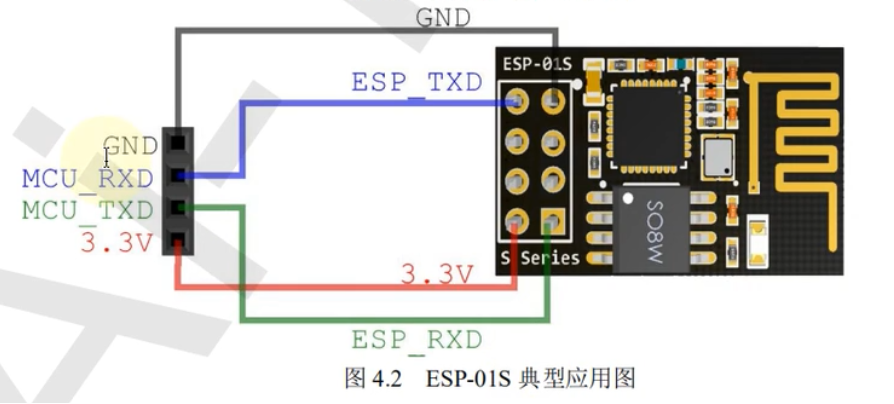
The ESP-01S module can be based on serial communication. Therefore, we use UART1 (corresponding to gpioB[17:16]) of hummingbird for development. First, initialize UART1, configure gpioB[17:16] to IOF mode, and use INIT_BOARD_EXPORT enables UART1 initialization to be performed automatically during the startup of the operating system.
void wifi_init() {
    gpio_iof_config(GPIOB, IOF_UART_MASK);
    uart_init(UART1, 115200);
}
INIT_BOARD_EXPORT(wifi_init);
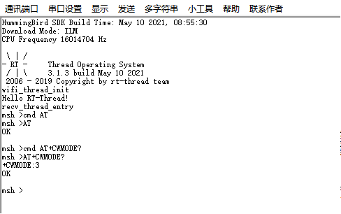
Then the AT instruction is sent. In order to facilitate the instruction test, the cmd function is exported to msh, so that the instruction can be directly sent to the wifi module through the terminal during the operation of RT thread. For example, by entering "cmd AT" and pressing enter, the AT command is sent to the wifi module, and the "OK" character will be received and printed, indicating that the module can be accessed normally.
void wifi_cmd(char *cmd, int wait_time) {
    send_str(cmd);
    rt_thread_mdelay(wait_time);
}

int cmd(int argc, char **argv) {
    if(argc != 2) {
        rt_kprintf("USE: %s \n", argv[0]);
        return RT_ERROR;
    }
    wifi_cmd(argv[1], 0);
    return RT_EOK;
}
MSH_CMD_EXPORT(cmd, send wifi cmd.)
Next, you need to implement the function to receive the characters returned by the ESP8266 module, which is implemented by a separate thread. Because hummingbird does not provide the method of directly accessing the uart receiving area like some STM32 microcontrollers, we need to read the contents of the uart buffer by continuously reading a single character, and print the received line of characters when encountering line feed.
void recv_thread_entry(void *parameter) {
    int i = 0;
    char ch;
    while (1) {
        ch = wifi_read(UART1);
        if (ch == '\r' || ch == '\n') {
            recv_buff[i] = '\0';
            if (rt_strlen(recv_buff) > 0) {
                i = 0;
                rt_kprintf("%s\n", recv_buff);
            }
        }
        else {
            recv_buff[i] = ch;
            i++;
        }
    }
}
Create a static thread and start it with the system:
int wifi_thread_init(void) {
    rt_kprintf("wifi_thread_init\n");
    rt_err_t ret = RT_EOK;
    rt_thread_t tid = &recv_thread;
    ret = rt_thread_init(&recv_thread,
                        "receive_thread",
                        recv_thread_entry, RT_NULL,
                        &recv_thread_stack[0], sizeof(recv_thread_stack),
                        RECV_THREAD_PRIORITY, 10);
    if (tid != RT_NULL && ret == RT_EOK)
        rt_thread_startup(tid);
    return RT_EOK;
}
INIT_APP_EXPORT(wifi_thread_init);
The above has completed the command sending and character receiving, and realized the communication between the board and ESP8266 module. The test results are as follows, which can be further developed on this basis.