1. Preface
MIZ7035 officially provides two kinds of pcie demo s, one is the ordinary PIO test and the other is the BMD test. I just tested the PIO function, which can read and write IO registers directly to the board. Another BMD function uses DMA to speed up data reading and writing.
It's also my first time to contact PCIe. BMD can also meet the application requirements. There should be no problem. I'm going to start the experiment with this. I asked the second tutor before the school. He directly said five letters to me: R-I-F-F-A. Let me check. The underlying FPGA and the upper software are already a complete architecture and can be used directly. Since the teacher said, this method must be more convenient, and he said he has been using this architecture.
2.RIFFA and XILLYBUS
First, baidu discussed the communication mode between CPU and FPGA, and found a problem:
What are the methods of data communication between CPU and FPGA?
Respondents directly posted two available frames:
XILLYBUS:
An FPGA IP core for easy DMA over PCIe with Windows and Linux
RIFFA2:
RIFFA: Home | RIFFA: A Reusable Integration Framework For FPGA Accelerators
There is also a framework of the Peking University wireless reconfigurable architecture research group:
EPEE:
EPEE – An Efficient and Flexible Host-FPGA PCIe Communication Library
XILLYBUS
XILLYBUS was first contacted when participating in the OpenHW2014 competition. I really didn't know what it was for at that time. At that time, zybo and zedboard were used to compete. XILLYBUS provided an Ubuntu operating system called Xillinux that could run on these two development boards, which was very powerful. Although the Ubuntu interface is slightly stuck on the Zynq device without GPU support, it is a complete desktop operating system after all. Many of us who participated in the competition started on it. In part, many people don't know petalinx, and it's more difficult to add their own desktop. After checking, Xillinux 2.0 beta version has been launched. Go and have a try when you are free.
In Xillinux, an AXI interface xillybus was officially provided. At that time, I didn't know what it was for. Now I finally understand.. It was originally designed to be compatible with its PCIe interface driver. Xillybus is mainly driven by his PCIe interface.
The following figure shows the structure of Xillybus
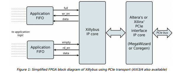
Xillybus is a PCIe interface core using Altera or Xilinux. It accesses its own Xillybus IP core, and finally maps TX and RX channels through FIFO interface. The structure is very clear. All we need is to access our own IP core after the FIFO interface and communicate according to our own protocol.
The upper layer code directly controls the sending and receiving data of the bottom FIFO by opening the device named xillybus and then reading and writing the file
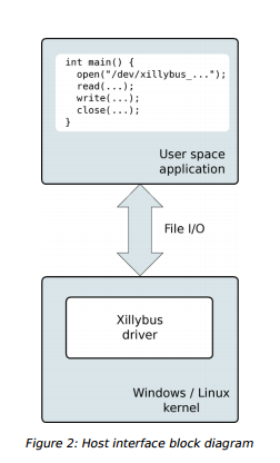
In this way, Xillybus of PCIe interface is another embedded Linux system independent of PCIe interface FPGA or Windows and Linux operating system of desktop.
The HOST corresponding to Xillybus of AXI interface is the ARM processor on its own Zynq device.
RIFFA
RIFFA is the first contact, and its structure is shown in the figure below
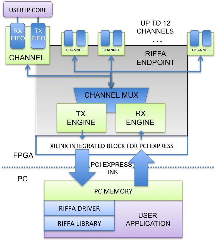
Firstly, the FPGA part is the PCIe core of Xilinx, and then uses TX and RX engines to map to up to 12 TX and RX channels after channel arbitration. The structure is similar to that of PIO and BMD, and the function of channel extension is added, so we don't have to write arbitration code ourselves.
The PC part is the basic driver and application structure. The access space of PCIe is mapped to the memory of PC. the driver of RIFFA is responsible for the management of memory and PCIe interface. The RIFFA library can be called by the user space program to call the underlying RIFFA driver and finally realize the data communication of PCIe.
The read-write function of RIFFA is called fpga_recv and FPGA_ The send function interface is also similar to a file read / write command, except that you can specify the PCIe channel number, data size and other information in the parameters.
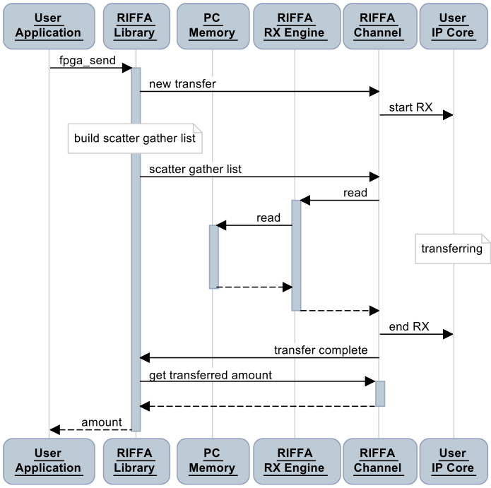
fpga_send process:
fpga_recv process:
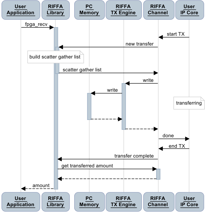
There is a step called build scatter gather list. My understanding is that when malloc applies for memory on PC, it is easy to apply for discontinuous physical memory, which may be divided into several blocks. Therefore, separate these spaces and generate this list, and then send the list information to PCIe endpoint, EP then uses DMA to directly operate the memory space on the PC according to this list.
Seeing the above two pictures, I'm really glad I didn't try to do it myself. I don't have so much time to do it, and I don't feel that I have the ability.
EPEE
The block diagram of EPEE is as follows:

If you don't look carefully, you won't analyze it.
The three frameworks mentioned above can certainly be used, but listen to the teacher's suggestions and go directly to RIFFA. There is no reason.
2. Establish RIFFA project
Go online to download the official RIFFA source file. You need to fill in some information to get the download address: http://riffa.ucsd.edu/download
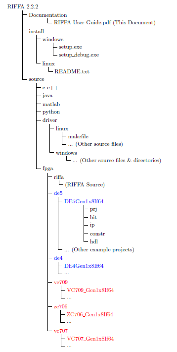
I directly downloaded the latest release version of RIFFA 2.2.2
Unzipped file structure:
ZC706 Demo
./ You can see the demo of xilinx development board in source/fpga/xilinx directory. zynq chip of MIZ7035 is closest to zc706 development board. We will use this demo for reference.
Use vivado to directly open the project. / source/fpga/xilinx/zc706/ZC706_Gen2x4If128/prj/ZC706_Gen2x4If128.xpr, click to automatically upgrade to Vivado 2017.4.
After updating the software dependencies, it is found that some files are missing in the project. These files are the hdl code related to riffa. We directly add the directory. / source / FPGA / riffa in the project_ All files under hdl, and check the two options in the red box
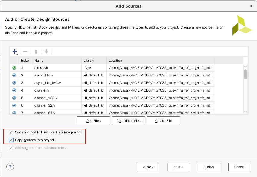
Click Finish and wait for the update of the file structure. You can see that there are no error warnings.
You can delete one more verilog file related to altera. Because I don't have the development board of ZC706, I won't integrate it. I'll experiment directly on MIZ7035.
MIZ7035 engineering design
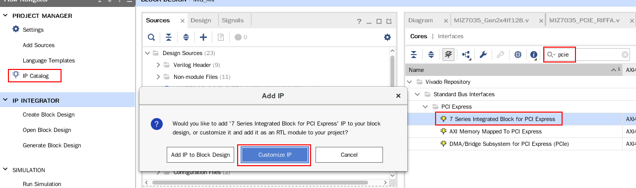
Continue to add the HDMI and MIG projects tested in the previous section to the PCIe function, click IP catalog - > search for PCIe - > double click 7 series integrated block for PCI Express - > select Customize IP. You cannot add IP to BD here because this IP Core is contained in another hdl file.
In order to facilitate migration, open the PCIe IP in ZC706 Demo and miz7035 project at the same time, and configure the IP of miz7035 according to the configuration of demo. Maps:
X4,5.0GT/s,100MHz Ref clock:
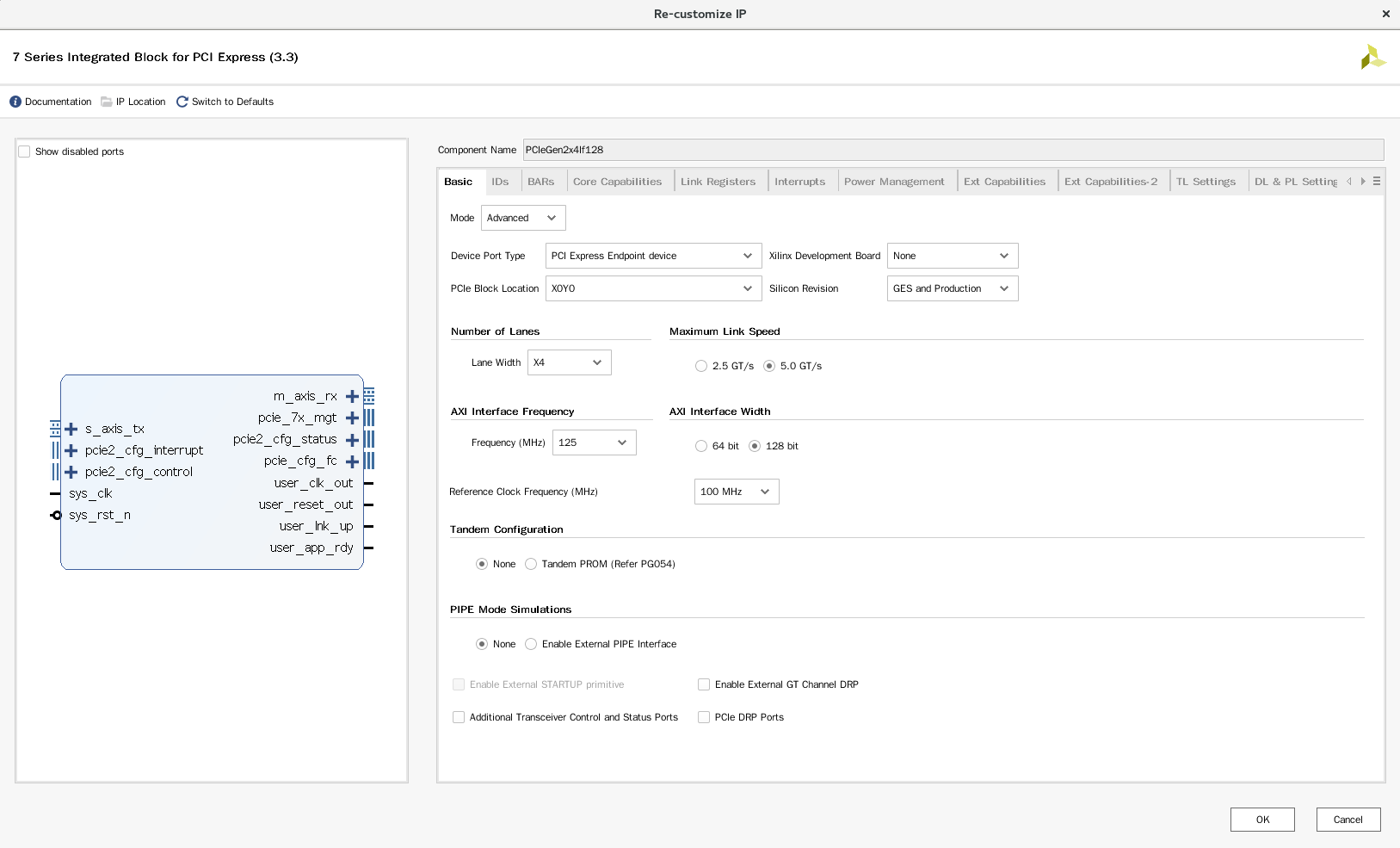
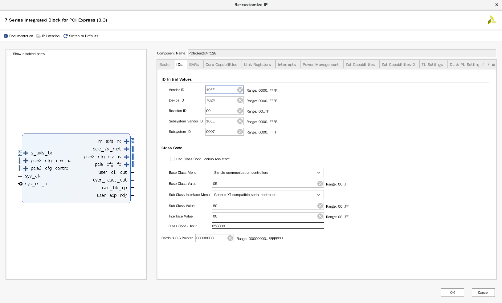
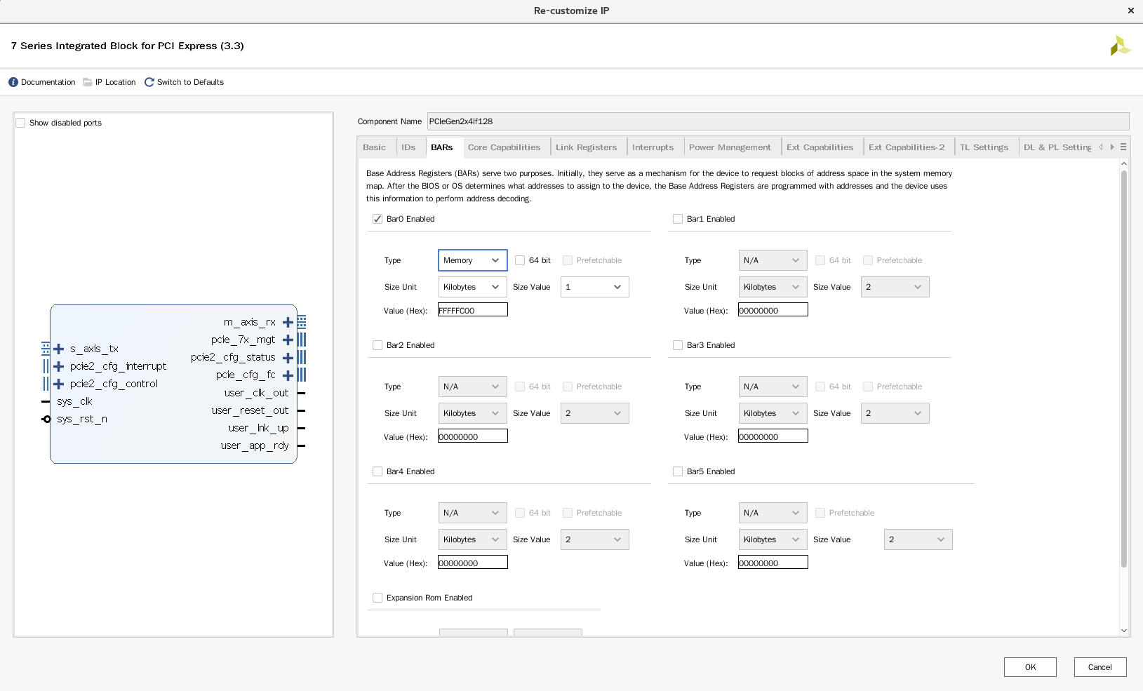
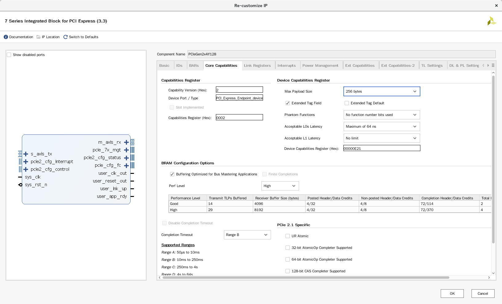
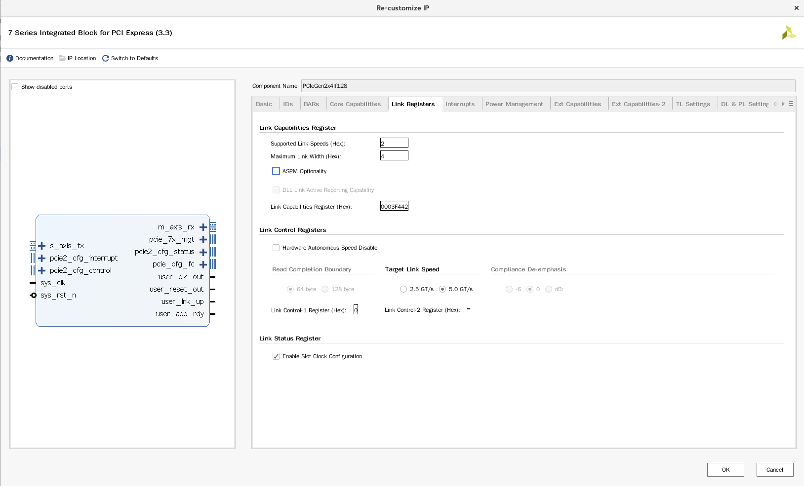
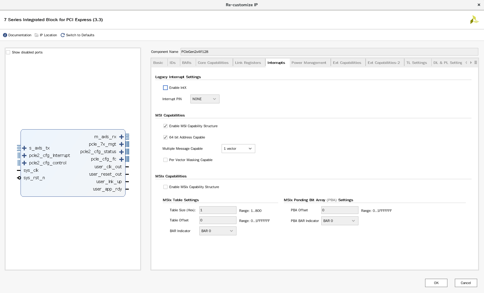
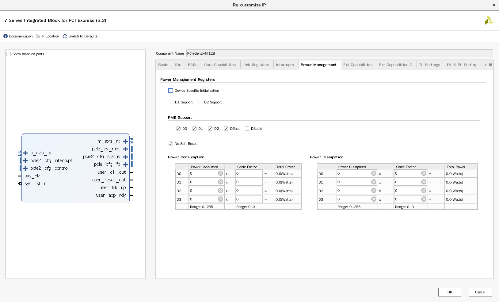
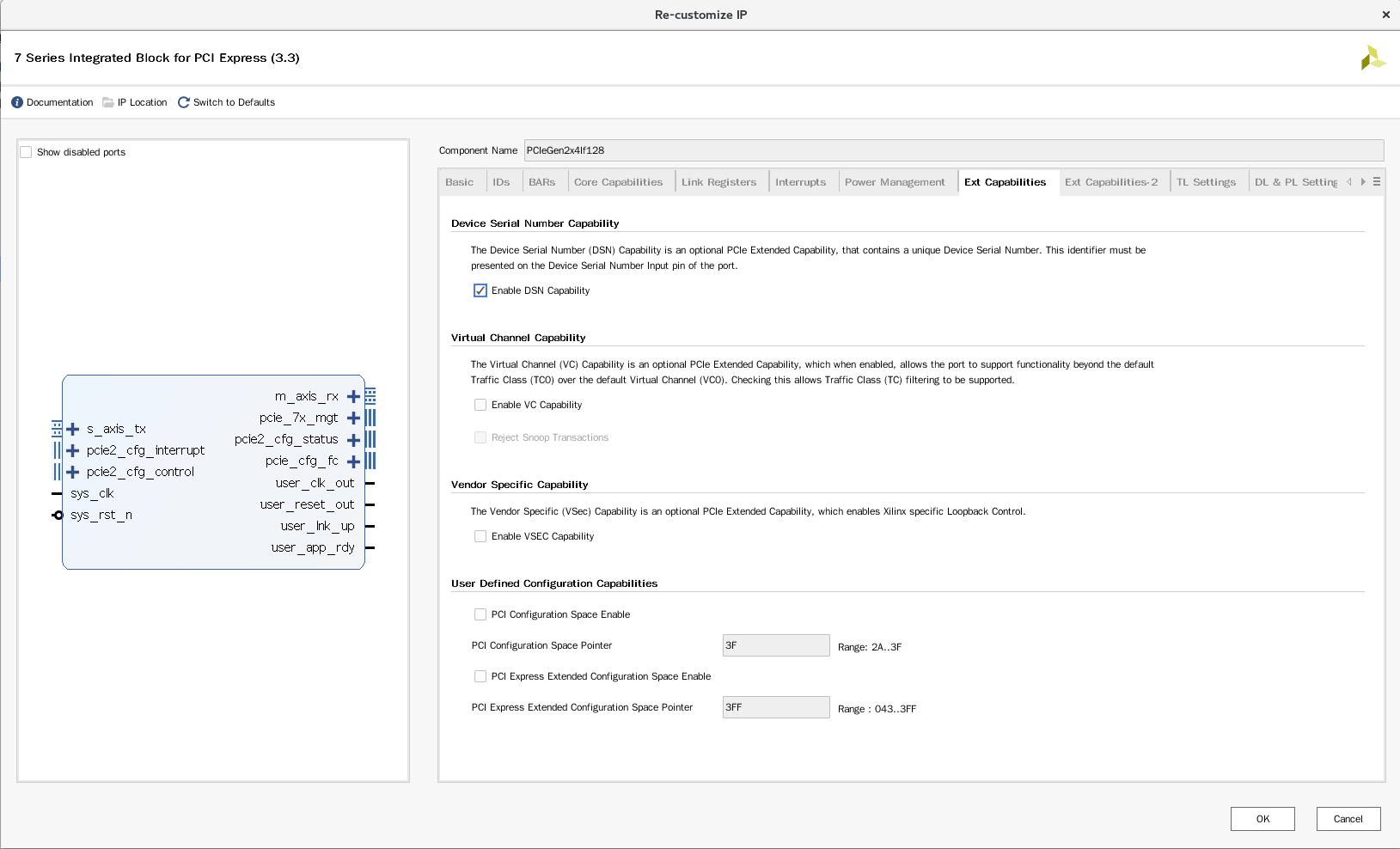
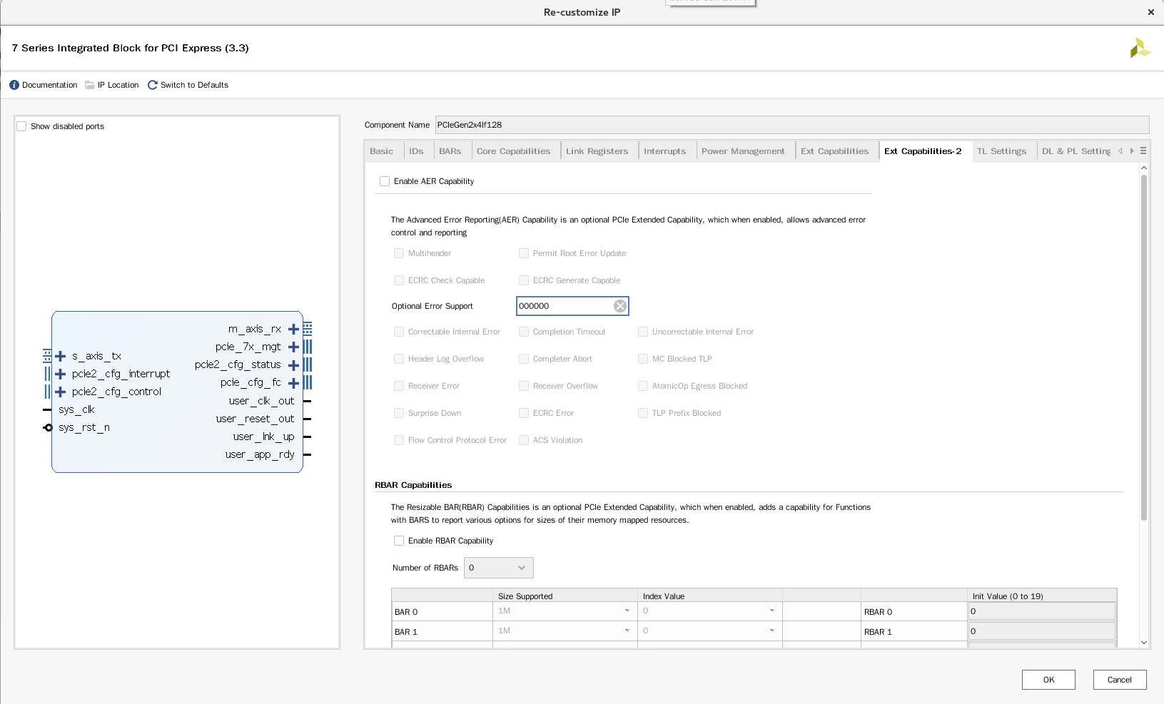
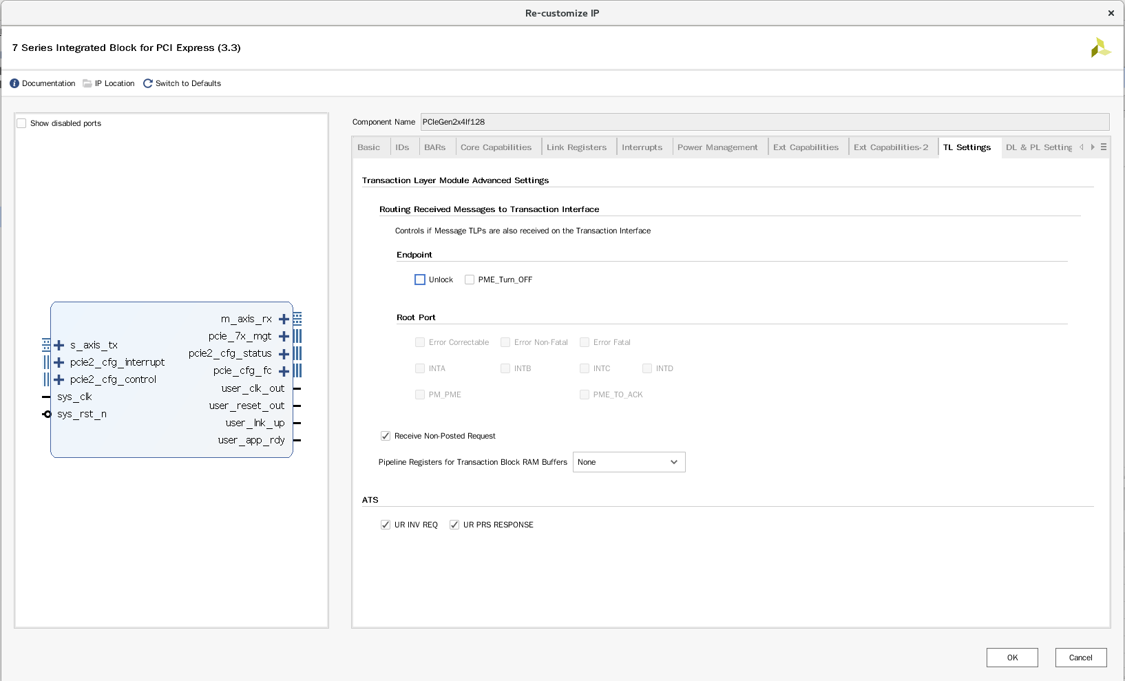
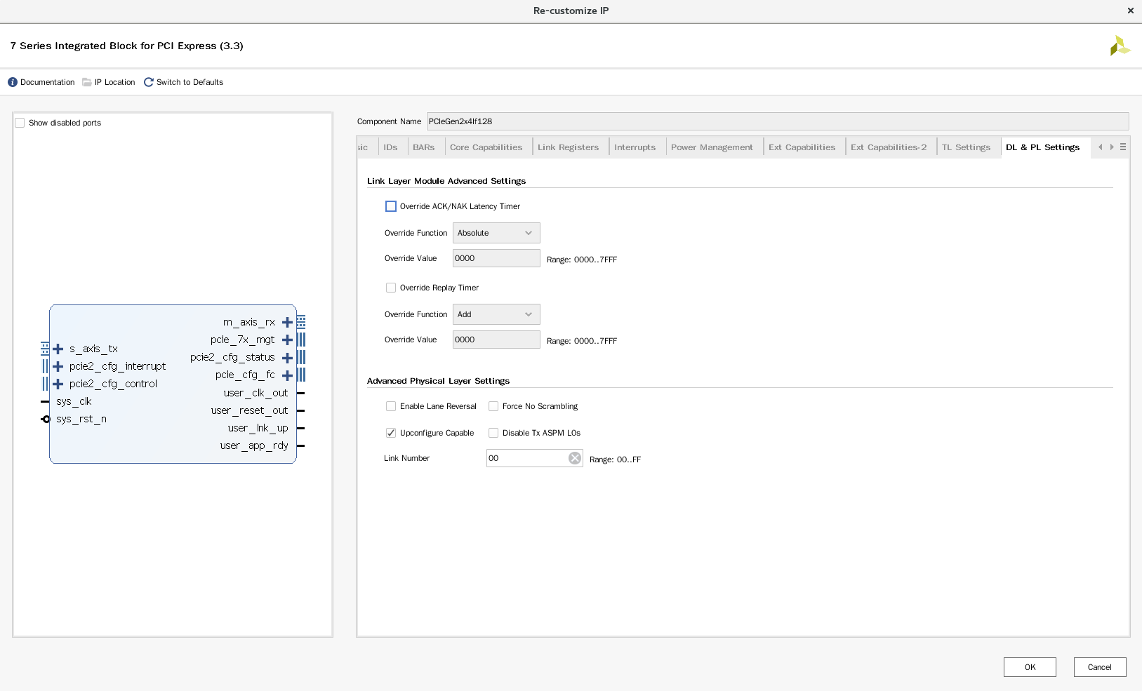
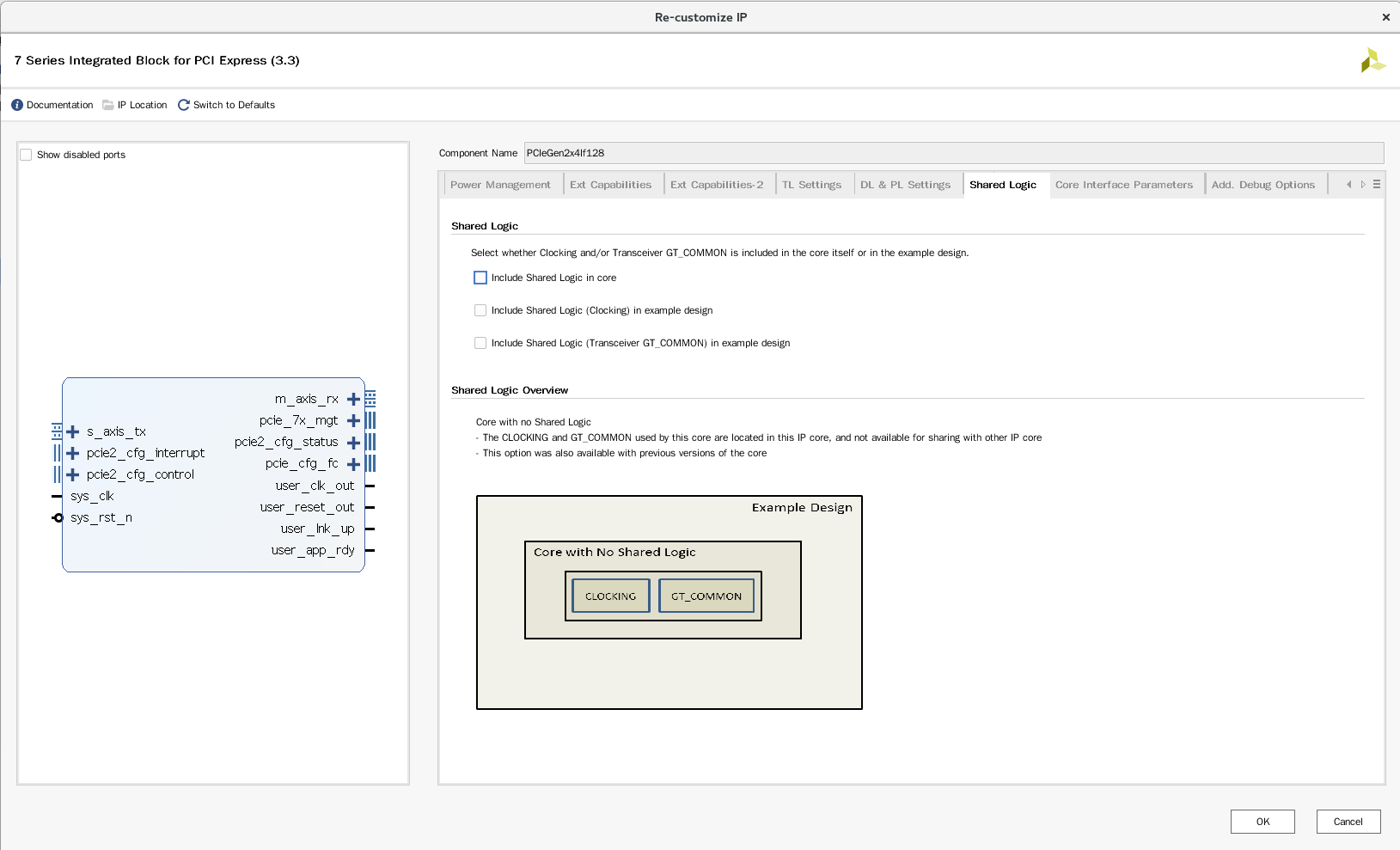
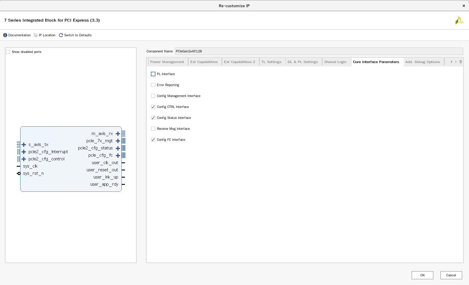
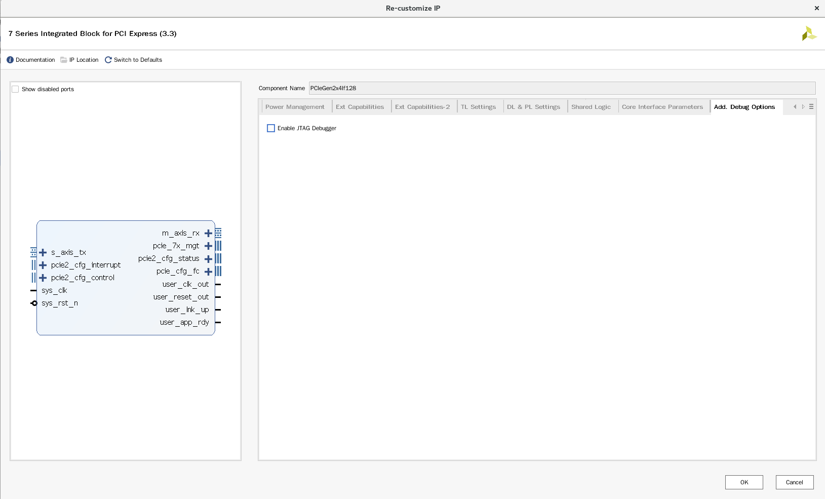
Regardless of the significance of each configuration, it should be no problem to follow the demo.
Create a new file MIZ7035 in your own project_ Gen2x4lf128. V, and then copy. / source/fpga/xilinx/zc706/ZC706_Gen2x4If128/hdl/ZC706_Gen2x4If128.v and paste it in. Change all zc706 characters to MIZ7035, and there is no need to modify others.
Create a new file Riffa in your own project_ wrapper_ MIZ7035. V, and then copy. / source/fpga/xilinx/zc706/riffa_wrapper_zc706.v and paste it in. Change all ZC706 characters to MIZ7035, and there is no need to modify others.
Then, when updating the file directory, you will be prompted that the file is missing. Then, according to the method just described in the demo, set. / source / FPGA / Riffa_ Add all files under HDL to the project and wait for updates. You can delete unnecessary files.
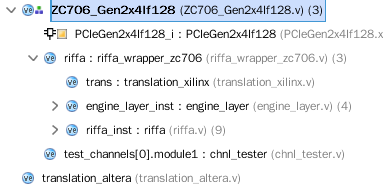
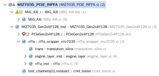
The final catalogue is as follows
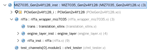
Because there was BD in my previous project, in order to exemplify a miz7035_ For the gen2x4lf128 module, you need to re instantiate BD and this module, and then use them as the top-level file.
Create a new MIZ7035_PCIE_RIFFA.v file, copy the wrapper code generated by BD before and copy it in. Delete the wrapper of the original BD. Miz7035 is described below_ Gen2x4lf128 is instantiated.
module MIZ7035_PCIE_RIFFA(
//pcie
    PCI_EXP_TXP,
    PCI_EXP_TXN,
    PCI_EXP_RXP,
    PCI_EXP_RXN,

    PCIE_REFCLK_P,
    PCIE_REFCLK_N,
    PCIE_RESET_N,
...
...
parameter C_NUM_LANES =  4;

output [(C_NUM_LANES - 1) : 0] PCI_EXP_TXP;
 output [(C_NUM_LANES - 1) : 0] PCI_EXP_TXN;
 input [(C_NUM_LANES - 1) : 0]  PCI_EXP_RXP;
 input [(C_NUM_LANES - 1) : 0]  PCI_EXP_RXN;

 input                          PCIE_REFCLK_P;
 input                          PCIE_REFCLK_N;
 input                          PCIE_RESET_N;

 MIZ7035_Gen2x4If128 MIZ7035_Gen2x4If128_inst
 (
    .PCI_EXP_TXP(PCI_EXP_TXP),
    .PCI_EXP_TXN(PCI_EXP_TXN),
    .PCI_EXP_RXP(PCI_EXP_RXP),
    .PCI_EXP_RXN(PCI_EXP_RXN),

    .LED(),
    .PCIE_REFCLK_P(PCIE_REFCLK_P),
    .PCIE_REFCLK_N(PCIE_REFCLK_N),
    .PCIE_RESET_N(PCIE_RESET_N)
);
endmodule
The new miz7035_ PCIE_ The Riffa. V file is the top-level file.
The final directory is as follows:
One of them is Chnl_ The code of tester is as follows:
`timescale 1ns/1ns
module chnl_tester #(
    parameter C_PCI_DATA_WIDTH = 9'd32
)
(
    input CLK,
    input RST,
    output CHNL_RX_CLK,
    input CHNL_RX,
    output CHNL_RX_ACK,
    input CHNL_RX_LAST,
    input [31:0] CHNL_RX_LEN,
    input [30:0] CHNL_RX_OFF,
    input [C_PCI_DATA_WIDTH-1:0] CHNL_RX_DATA,
    input CHNL_RX_DATA_VALID,
    output CHNL_RX_DATA_REN,

    output CHNL_TX_CLK,
    output CHNL_TX,
    input CHNL_TX_ACK,
    output CHNL_TX_LAST,
    output [31:0] CHNL_TX_LEN,
    output [30:0] CHNL_TX_OFF,
    output [C_PCI_DATA_WIDTH-1:0] CHNL_TX_DATA,
    output CHNL_TX_DATA_VALID,
    input CHNL_TX_DATA_REN
);

reg [C_PCI_DATA_WIDTH-1:0] rData={C_PCI_DATA_WIDTH{1'b0}};
reg [31:0] rLen=0;
reg [31:0] rCount=0;
reg [1:0] rState=0;

assign CHNL_RX_CLK = CLK;
assign CHNL_RX_ACK = (rState == 2'd1);
assign CHNL_RX_DATA_REN = (rState == 2'd1);

assign CHNL_TX_CLK = CLK;
assign CHNL_TX = (rState == 2'd3);
assign CHNL_TX_LAST = 1'd1;
assign CHNL_TX_LEN = rLen; // in words
assign CHNL_TX_OFF = 0;
assign CHNL_TX_DATA = rData;
assign CHNL_TX_DATA_VALID = (rState == 2'd3);

always @(posedge CLK or posedge RST) begin
    if (RST) begin
        rLen <= #1 0;
        rCount <= #1 0;
        rState <= #1 0;
        rData <= #1 0;
    end
    else begin
        case (rState)

        2'd0: begin // Wait for start of RX, save length
            if (CHNL_RX) begin
                rLen <= #1 CHNL_RX_LEN;
                rCount <= #1 0;
                rState <= #1 2'd1;
            end
        end

        2'd1: begin // Wait for last data in RX, save value
            if (CHNL_RX_DATA_VALID) begin
                rData <= #1 CHNL_RX_DATA;
                rCount <= #1 rCount + (C_PCI_DATA_WIDTH/32);
            end
            if (rCount >= rLen)
                rState <= #1 2'd2;
        end

        2'd2: begin // Prepare for TX
            rCount <= #1 (C_PCI_DATA_WIDTH/32);
            rState <= #1 2'd3;
        end

        2'd3: begin // Start TX with save length and data value
            if (CHNL_TX_DATA_REN & CHNL_TX_DATA_VALID) begin
                rData <= #1 {rCount + 4, rCount + 3, rCount + 2, rCount + 1};
                rCount <= #1 rCount + (C_PCI_DATA_WIDTH/32);
                if (rCount >= rLen)
                    rState <= #1 2'd0;
            end
        end

        endcase
    end
end
CHNL is an interface similar to FIFO or AXIS implemented by RIFFA. This file is equivalent to a loopback. RX saves the last data received, and then uses TX to increase the data by one value each time before sending it out. This test and the host computer test code will be able to test the bandwidth of PCIe together.
Then in the previous miz7035_ Add constraints to io.xdc:
#PCIe
set_property IOSTANDARD LVCMOS33 [get_ports PCIE_RESET_N]
set_property PACKAGE_PIN V19 [get_ports PCIE_RESET_N]
set_property PULLUP true [get_ports PCIE_RESET_N]
set_false_path -from [get_ports PCIE_RESET_N]

create_clock -period 10.000 -name sys_clk [get_ports PCIE_REFCLK_P]
set_property PACKAGE_PIN W6 [get_ports PCIE_REFCLK_P]
set_property PACKAGE_PIN W5 [get_ports PCIE_REFCLK_N]

set_property PACKAGE_PIN AC2 [get_ports {PCI_EXP_TXP[0]}]
set_property PACKAGE_PIN AE2 [get_ports {PCI_EXP_TXP[1]}]
set_property PACKAGE_PIN AF4 [get_ports {PCI_EXP_TXP[2]}]
set_property PACKAGE_PIN AF8 [get_ports {PCI_EXP_TXP[3]}]

set_property PACKAGE_PIN AC1 [get_ports {PCI_EXP_TXN[0]}]
set_property PACKAGE_PIN AE1 [get_ports {PCI_EXP_TXN[1]}]
set_property PACKAGE_PIN AF3 [get_ports {PCI_EXP_TXN[2]}]
set_property PACKAGE_PIN AF7 [get_ports {PCI_EXP_TXN[3]}]

set_property PACKAGE_PIN AD4 [get_ports {PCI_EXP_RXP[0]}]
set_property PACKAGE_PIN AC6 [get_ports {PCI_EXP_RXP[1]}]
set_property PACKAGE_PIN AE6 [get_ports {PCI_EXP_RXP[2]}]
set_property PACKAGE_PIN AD8 [get_ports {PCI_EXP_RXP[3]}]

set_property PACKAGE_PIN AD3 [get_ports {PCI_EXP_RXN[0]}]
set_property PACKAGE_PIN AC5 [get_ports {PCI_EXP_RXN[1]}]
set_property PACKAGE_PIN AE5 [get_ports {PCI_EXP_RXN[2]}]
set_property PACKAGE_PIN AD7 [get_ports {PCI_EXP_RXN[3]}]
In this way, we can synthesize, implement and generate bit.
Take a look at the implemented Schematic
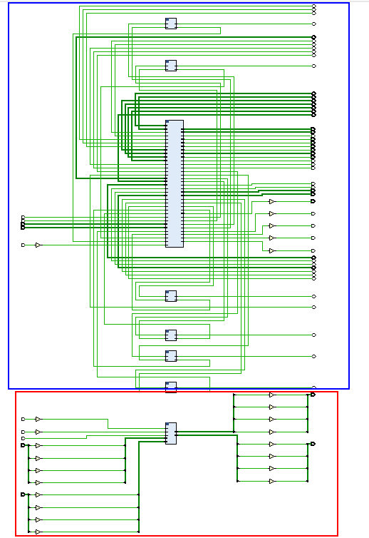
The red box is PCIe related, and the blue box is previous HDMI and MIG related. It can be seen that there is no direct connection between the two, and indeed we have not added the communication relationship between them. After verifying the interface, I will use its CHNL channel to realize the connection of video data.
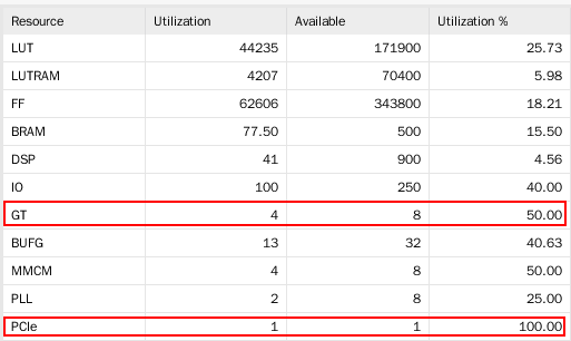
Taking up resources, you can see that we use an X4 PCIe
Output to SDK, create a new fsbl project to show the original project, and then generate a BOOT.bin. Copy the file to SD card, insert it into MIZ7035, and change the startup mode of development board to SD card startup, so that we don't need JTAG to download.
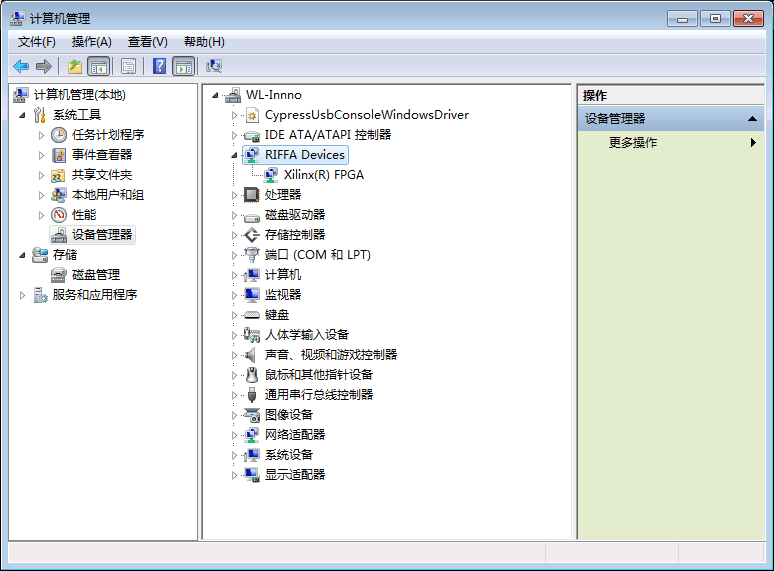
Plug the development board into the computer and power it on, then start the PC. you can see our equipment with the previously installed Windriver, indicating that the PCIe interface has been started. Let's test with RIFFA.
3. Installation of Riffa drive
Windows RIFFA
Take a look at. / install/windows/README.txt first
It says that it can only support 32-bit and 64 bit systems of Windows 7.
See. / source/driver/windows/README.txt again
Debugging on Windows is difficult because there exists no kernel log file
I also tried, WDK really can't use, and there are errors when compiling. Try again when you are free. I also installed it. When you start the computer, you can find our device
WDK download address for Windows 7: Download Windows Driver Kit Version 7.1.0 from Official Microsoft Download Center
Linux RIFFA
./install/linux/README.txt
It says that you can directly compile and install the driver under the driver directory
./source/driver/linux/README.txt
It says the installation instructions of the driver
$ sudo make setup
$ make
$ sudo make install
It's easy to install. When writing an application, you can directly include riffa.h and link -lriffa. It looks very convenient.
The problem comes again. There is no Linux physical machine on my computer, and the VMWare virtual machine does not support the connection of PCIe devices. It is inconvenient for other people's computers. The PCI of zcu102 petalinux has not been compiled before. In front of me, I saw a TX1 development board. Why?
Linux RIFFA TX1
Plug the MIZ7035 into the PCIe slot of TX1, turn on the power of MIZ7035, and wait for the SDK to start successfully. Connect the network cable and HDMI display on TX1, press the POWER BTN button of TX1 to open the TX1 development board. I directly logged in to the command line of TX1 through the network with Xshell.
Look at pci devices
ubuntu@tegra-ubuntu:~$ lspci
00:01.0 PCI bridge: NVIDIA Corporation Device 0fae (rev a1)
01:00.0 Memory controller: Xilinx Corporation Device 7024
You can see that the PCIe of MIZ7035 has been recognized. Use USB flash disk or TFTP to set. / source/driver,. / source / C_ Copy C + +,. / source/python to the development board, and then enter the. / driver/linux / directory for execution
$ sudo make setup
The result indicates that the package cannot be found when installing linux-headers-3.10.96-tegra. There is no clear answer on the Internet. Try to execute the make command. Through the warning message, you can see that you have located the directory / usr/src/linux-headers-3.10.96-tegra
View README under this directory,
These headers are provided to enable external module builds. They must be prepared on the target system before being used for module compilation. To prepare the headers, go into the headers package top level directory, and issue the following command:
sudo make modules_prepare
After preparation completes, external modules can be built following the process described in Documentation/kbuild/modules.txt.
It turns out that the Linux headers of TX1 tegra cannot be found from the apt get source. We need to directly use the development board to provide them. Just compile them.
Execute the command in this directory to compile Linux headers
$ sudo make modules_prepare
Return to the. / driver/linux / directory just now
$ sudo make setup
$ make
$ sudo make install
In this way, the function of riffa seems to be compiled, and the exciting test is about to begin.
Enter directory. / c_c++/linux/x64/sample_app, which is used to correspond to Chnl in FPGA_ Of the tester module. compile:
$ make clean
$ make
Before testing, you can look at the source code to understand the test commands. Test:
ubuntu@tegra-ubuntu:~/pcie/c_c++/linux/x64/sample_app$ ./testutil 0
Number of devices: 1
0: id:0
0: num_chnls:1
0: name:0000:01:00.00
0: vendor id:10EE
0: device id:7024
ubuntu@tegra-ubuntu:~/pcie/c_c++/linux/x64/sample_app$ ./testutil 1 0
ubuntu@tegra-ubuntu:~/pcie/c_c++/linux/x64/sample_app$ ./testutil 2 0 0 5000000
words sent: 5000000
words recv: 5000000
recvBuffer[0]: 4999997
recvBuffer[1]: 4999998
recvBuffer[2]: 4999999
recvBuffer[3]: 5000000
recvBuffer[4]: 5
recvBuffer[5]: 6
recvBuffer[6]: 7
recvBuffer[7]: 8
recvBuffer[8]: 9
recvBuffer[9]: 10
recvBuffer[10]: 11
recvBuffer[11]: 12
recvBuffer[12]: 13
recvBuffer[13]: 14
recvBuffer[14]: 15
recvBuffer[15]: 16
recvBuffer[16]: 17
recvBuffer[17]: 18
recvBuffer[18]: 19
recvBuffer[19]: 20
recvBuffer[4463772]: 0, expected 4463773
send bw: 943.800814 MB/s 20.209229ms
recv bw: 588.343826 MB/s 32.418945ms
ubuntu@tegra-ubuntu:~/pcie/c_c++/linux/x64/sample_app$ ./testutil 2 0 0 93312000
words sent: 93312000
words recv: 93312000
recvBuffer[0]: 93311997
recvBuffer[1]: 93311998
recvBuffer[2]: 93311999
recvBuffer[3]: 93312000
recvBuffer[4]: 5
recvBuffer[5]: 6
recvBuffer[6]: 7
recvBuffer[7]: 8
recvBuffer[8]: 9
recvBuffer[9]: 10
recvBuffer[10]: 11
recvBuffer[11]: 12
recvBuffer[12]: 13
recvBuffer[13]: 14
recvBuffer[14]: 15
recvBuffer[15]: 16
recvBuffer[16]: 17
recvBuffer[17]: 18
recvBuffer[18]: 19
recvBuffer[19]: 20
recvBuffer[702060]: 0, expected 702061
send bw: 1028.932190 MB/s 345.947998ms
recv bw: 1577.181281 MB/s 225.691895ms
Let's analyze the test instructions
1. Instruction 0 is used to list all PCIe RIFFA devices and print out their RIFFA id, number of internal chnl channels, device name, manufacturer and device id.
2. Instruction 1 is used to reset the PCIe core
3. Instruction 2 is used to test the transceiver function and speed of PCIe. The last parameter specifies the number of words (4 bytes) to be tested.
4. 5000000 word s were tested for the first time, about 19MB, with a speed of
send bw: 943.800814 MB/s 20.209229ms
recv bw: 588.343826 MB/s 32.418945ms
5. One 1920 was tested for the first time* 1080@60Hz 24bit image size packet, about 356MB, speed
send bw: 1028.932190 MB/s 345.947998ms
recv bw: 1577.181281 MB/s 225.691895ms
The theoretical bandwidth of PCIe Gen2 x 4 is 2000MB/s. It seems that this RIFFA will suffer some losses, but it is acceptable.
python testing
ubuntu@tegra-ubuntu:~/pcie/python$ sudo python setup.py install
ubuntu@tegra-ubuntu:~/pcie/python$ cd sample_app/
ubuntu@tegra-ubuntu:~/pcie/python/sample_app$ vim sampleapp.py
 The in the script amt Change to 20 :wq
ubuntu@tegra-ubuntu:~/pcie/python/sample_app$ python sampleapp.py
array('I', [1L, 2L, 3L, 4L, 5L, 6L, 7L, 8L, 9L, 10L, 11L, 12L, 13L, 14L, 15L, 16L, 17L, 18L, 19L, 20L])
array('I', [17L, 18L, 19L, 20L, 5L, 6L, 7L, 8L, 9L, 10L, 11L, 12L, 13L, 14L, 15L, 16L, 17L, 18L, 19L, 20L])
ubuntu@tegra-ubuntu:~/pcie/python/sample_app$
You can see that the first four data of the test have errors, and you don't know why. Leave it alone
4. Summary
This time, I used the RIFFA function recommended by the teacher to test the communication of PCIe. At first, I wanted to do all the work myself. Now it seems really unnecessary. After all, there are too many related things. I can stand the driver of linux kernel alone. RIFFA framework takes less than 5 hours from knowing the name, passing through the MIZ7035 development board to finally testing the bandwidth with test cases. It feels very efficient
Next, I need to get familiar with its CHNL interface, and then add my own channel to this interface to realize the first planned PCIe video transmission.