Bowen catalog
Write before
- Personal Blog Home Page
- Note: Learn to communicate!
text
FIFO in GA/ASIC
How FIFO buffers are used to transfer data and across clock domains
The abbreviation FIFO stands for First In First Out.FIFO is ubiquitous in the design of both the field programmer and ASIC, and they are one of the basic building blocks.And they're very convenient!FIFO can be used for any of the following purposes:
- Cross Clock Domain
- Buffer data before sending it off-chip (for example, to DRAM or SRAM)
- Buffer data for software to view later
- Store data for backup
FIFO can be thought of as a one-way tunnel through which a car can drive.At the end of the tunnel is a toll station with a door.Once the door opens, the car can leave the tunnel.If that door never opens and more cars continue to enter the tunnel, the tunnel will eventually be full of cars.This is called a FIFO overflow, which is usually not a good thing.The depth of the FIFO can be thought of as the length of the tunnel.The deeper the FIFO, the more data it can hold before overflowing.FIFO also has a width, which represents the width (in bits) of data entering FIFO.Below is an image of any FIFO basic interface.These signals are always found when you look at any FIFO.Usually, more signals add other functions, such as word count in FIFO.See the following figure:
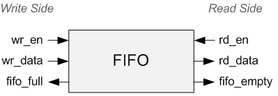
FIFO can be divided into write side and read side.Write side has signal Write enable wr_en","Write data wr_data"and"FIFO is full fifo_full".Designers should never write full FIFOs!Always check the FIFO full flag to make sure there is room to write another piece of data, otherwise you will lose the data.
The read side has the signal "Read enable rd_en","Read data rd_data"and"FIFO empty fifo_empty".Designers should never read empty FIFOs!As long as you follow these two basic rules, you and FIFO will get along well.I'll repeat that again, because they are so important.
Two FIFO rules:
- Never write a full FIFO
- Never read from an empty FIFO (underflow)
FIFO itself can be composed of dedicated logic within a field-bus or ASIC, or it can be created by triggers (distributed registers).Which of these two tools will be used by the comprehensive tool depends entirely on the vendor of the GA you are using and the structure of the code.Just know that when you use dedicated logical blocks, they perform better than register-based FIFOs.
FIFO is one of the basic building blocks for the designer of the field programmer, which is very important for correct understanding and correct use.
Design of synchronous FIFO
For simplicity, this paper first designs a synchronous FIFO with only the empty full flag.
Before giving the design of synchronous FIFO, it is necessary to say the principle of synchronous FIFO. The design of synchronous FIFO is necessary. It is the basis to lead to asynchronous FIFO. All the principles in synchronous FIFO are understood. What is the same in asynchronous FIFO and synchronous FIFO do not have to worry anymore, but go directly to the focus and control emptiness.
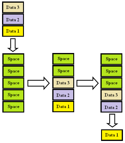
FIFO is an acronym for FIFO that describes how to manage data relative to time or priority.In this case, the first data to arrive will also be the first data to leave from a set of data.A FIFO buffer is a read/write storage array that automatically tracks the order in which data enters the module and reads out the data in the same order.In hardware, FIFO buffers are used for synchronization purposes.It is usually implemented as a circular queue with two pointers:
- Read Pointer/Read Address Register
- Write Pointer/Write Address Register
The read and write addresses are initially in the first memory location, and the FIFO queue is empty.When the difference between the read and write addresses of the FIFO buffer equals the size of the memory array, the FIFO queue is Full (for asynchronous FIFOs, multiple addresses can be designed to represent read and write pointers).
FIFO can be divided into synchronous or asynchronous clocks, depending on whether the same clock (synchronous) or different clocks (asynchronous) control read and write operations.
Synchronized FIFO is a FIFO design in which data values are written sequentially to the storage array using a clock signal and read out from the storage array sequence using the same clock signal.Figure 1 shows the typical FIFO process.
Look at another picture: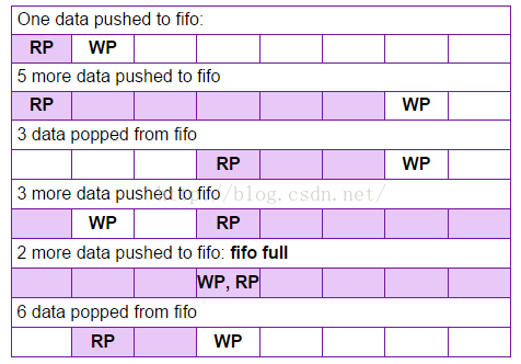
From this picture we can get the following information:
- Write Pointer WP always points to the address to be written by the next clock;
- The read pointer RP always points to the address to be read by the next clock;
- When the read pointer equals the write pointer, it may be empty or full.
These are all important points, we will slowly experience later.
Code Design
// Reborn Lee
// blog address: https://blog.csdn.net/Reborn_Lee
module syn_fifo#(
    parameter DATA_WIDTH = 8,
    parameter DATA_DEPTH = 8
    )(
    input i_clk,
    input i_rst,

    //write port
    input wr_en,
    input [DATA_WIDTH - 1 : 0] wr_data,
    output wr_full,
    //read port
    input rd_en,
    output [DATA_WIDTH - 1 : 0] rd_data,
    output rd_empty

);

    //define ram

    reg [DATA_WIDTH - 1 : 0] fifo_buffer[0 : DATA_DEPTH - 1];
    reg [$clog2(DATA_DEPTH) : 0] fifo_cnt = 0;

    reg [$clog2(DATA_DEPTH) - 1 : 0] wr_pointer = 0;
    reg [$clog2(DATA_DEPTH) - 1 : 0] rd_pointer = 0;

    // keep track of the  fifo counter
    always@(posedge i_clk) begin
        if(i_rst) begin
            fifo_cnt <= 0;
        end
        else begin
            if(wr_en && !rd_en) begin //wr_en is asserted and fifo is not full
                fifo_cnt <= fifo_cnt + 1;
            end
            else if(rd_en && !wr_en) begin // rd_en is asserted and fifo is not empty
                fifo_cnt <= fifo_cnt - 1;
            end
        end


    end

    //keep track of the write  pointer
    always@(posedge i_clk) begin
        if(wr_en && !wr_full) begin
            if(wr_pointer == DATA_DEPTH - 1) begin
                wr_pointer <= 0;
            end
            else begin
                wr_pointer <= wr_pointer + 1;
            end

        end

    end


    //keep track of the read pointer
    always@(posedge i_clk) begin
        if(rd_en && !rd_empty) begin
            if(rd_pointer == DATA_DEPTH - 1) begin
                rd_pointer <= 0;
            end
            else begin
                rd_pointer <= rd_pointer + 1;
            end
        end

    end

    //write data into fifo when wr_en is asserted
    always@(posedge i_clk) begin
        if(wr_en) begin
            fifo_buffer[wr_pointer] <= wr_data;
        end
    end

    //read data from fifo when rd_en is asserted
    //assign rd_data = (rd_en)?fifo_buffer[rd_pointer]: 'bz;
    assign rd_data = fifo_buffer[rd_pointer];

    assign wr_full = (fifo_cnt == DATA_DEPTH)? 1 : 0;
    assign rd_empty = (fifo_cnt == 0) ? 1 : 0;

endmodule
Test Platform:
`timescale 1ns / 1ps
////////////////////////////////////////////////////////////
// Engineer: Reborn Lee
// Module Name: syn_fifo_tb
//https://blog.csdn.net/Reborn_Lee
//////////////////////////////////////////////////////////


module syn_fifo_tb(

    );

	parameter DATA_WIDTH = 8;
    parameter DATA_DEPTH = 8;

    reg i_clk;
    reg i_rst;

    //write port
    reg wr_en;
    reg [DATA_WIDTH - 1 : 0] wr_data;
    wire wr_full;
    //read port
    reg rd_en;
    wire [DATA_WIDTH - 1 : 0] rd_data;
    wire rd_empty;


    initial begin
    	i_clk = 0;
    	forever begin
    		#5 i_clk = ~i_clk;
    	end
    end

    initial begin

    	i_rst = 1;
    	wr_en = 0;
    	rd_en = 0;

    	@(negedge i_clk) i_rst = 0;
    	@(negedge i_clk) wr_en = 1;
    	wr_data = $random;

    	repeat(3) begin
    		@(negedge i_clk)
    		wr_data = $random;
    	end


    	@(negedge i_clk)
    	wr_en = 0;
    	rd_en = 1;

    	repeat(3) begin
    		@(negedge i_clk);
    	end

    	@(negedge i_clk)
    	rd_en = 0;
    	wr_en = 1;
    	wr_data = $random;

    	repeat(7) begin
    		@(negedge i_clk)
    		wr_data = $random;
    	end

    	#20 $finish;


    end


	syn_fifo #(.DATA_WIDTH(DATA_WIDTH),.DATA_DEPTH(DATA_DEPTH))
	inst_syn_fifo
		(
			.i_clk    (i_clk),
			.i_rst    (i_rst),
			.wr_en    (wr_en),
			.wr_data  (wr_data),
			.wr_full  (wr_full),
			.rd_en    (rd_en),
			.rd_data  (rd_data),
			.rd_empty (rd_empty)
		);

endmodule
Simulated Waveform
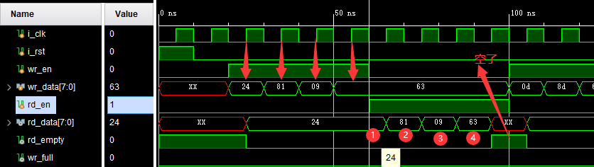
First look at the most intuitive information: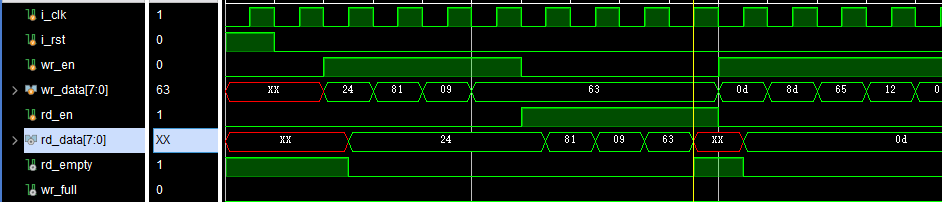
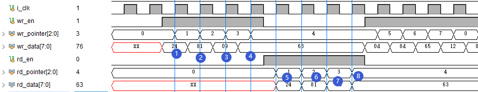
Writing FIFO data is 24,81,09,63, reading data (from read to start reading effectively) 24,81,09,63, a clock after reading is no longer read, the empty signal is raised, indicating that the read is empty.The following figures are illustrated with arrows and numbers:
Let's see if we write FIFO data 24,81,09,63:
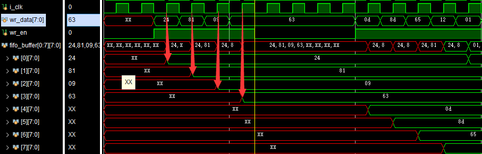
Such is the case!
Take another look at reading the data:
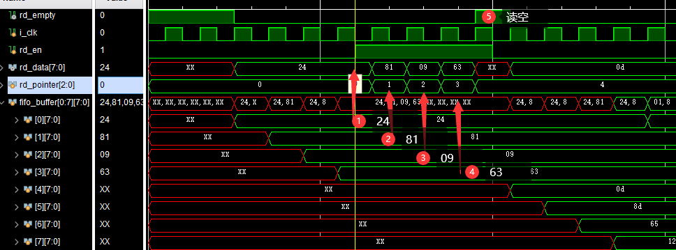
It does start with a 0 pointer.
As for what is red in some places of this FIFO, it is because there is no initial value assigned to the storage space of the FIFO, and it is shown red in the simulation, but it is unknown. In the actual field programmer or ASIC, it is actually a random value.
Let's look at the Write Pointer in the design code. The initial value is 0. When writing works, when the clock rises, add 1 to the Write Pointer:
//keep track of the write  pointer
    always@(posedge i_clk) begin
        if(wr_en && !wr_full) begin
            if(wr_pointer == DATA_DEPTH - 1) begin
                wr_pointer <= 0;
            end
            else begin
                wr_pointer <= wr_pointer + 1;
            end

        end

    end
In this case, FIFO is written when writing is effective and the clock rise is coming:
//write data into fifo when wr_en is asserted
    always@(posedge i_clk) begin
        if(wr_en) begin
            fifo_buffer[wr_pointer] <= wr_data;
        end
    end
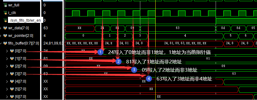
I want to remind you that the FIFO space address written at this time should be the address value (pointer value) before the pointer adds 1. This is because non-blocking assignment is used. Even if the pointer adds 1, the pointer of plus 1 is not effective when the clock rises and writes FIFO at this time. This is the role of non-blocking assignment.
Don't you believe it?
As mentioned above, in the simulation, the value of the pointer should be 1 greater than the address value written to FIFO.
Take a look at the simulation:
This is not a problem, but it should be raised for fear of some students'fans!
The Verilog design just now uses synchronous writing for writing, but asynchronous reading for reading. What if we use synchronous reading?To unify FIFO writing data, we can guess (with confidence in mind) that the reading pointer value exceeds the reading data address 1, that is, if the reading address rises by 2 on the clock, the current reading value is actually the value of 1 address.
Let's test it. Shilling read changes to synchronous read:
// assign rd_data = fifo_buffer[rd_pointer];

    always@(posedge i_clk) begin
    	if(rd_en) begin
    		rd_data <= fifo_buffer[rd_pointer];
    	end
    end
Then the simulation results are observed:
Data access is okay, FIFO.
However, another situation you can see is that when 1 address, both the data stored and the data obtained are actually 0 address data.Continue with the simulation:
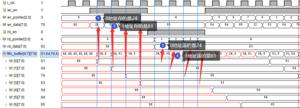
It can be seen that although the address becomes 1 at this time, it is not valid for FIFO. Store and fetch are still stored or fetched according to the previous address, which is the reason for non-blocking assignment.
But these details will not affect our use of FIFO, we do not need to pay attention to them when using FIFO, we just need to access them first in, first out.
Encapsulate into FIFO module, use it!But for digital designers, you still need to know the details. Otherwise, FIFO is soulless, and what if an interview or written test lets you write a FIFO?
Now that it's design, you have to know the details, because it's the details of your design.
VHDL version design
library ieee;
use ieee.std_logic_1164.all;
use ieee.numeric_std.all;

entity module_fifo_regs_no_flags is
  generic (
    g_WIDTH : natural := 8;
    g_DEPTH : integer := 32
    );
  port (
    i_rst_sync : in std_logic;
    i_clk      : in std_logic;

    -- FIFO Write Interface
    i_wr_en   : in  std_logic;
    i_wr_data : in  std_logic_vector(g_WIDTH-1 downto 0);
    o_full    : out std_logic;

    -- FIFO Read Interface
    i_rd_en   : in  std_logic;
    o_rd_data : out std_logic_vector(g_WIDTH-1 downto 0);
    o_empty   : out std_logic
    );
end module_fifo_regs_no_flags;

architecture rtl of module_fifo_regs_no_flags is

  type t_FIFO_DATA is array (0 to g_DEPTH-1) of std_logic_vector(g_WIDTH-1 downto 0);
  signal r_FIFO_DATA : t_FIFO_DATA := (others => (others => '0'));

  signal r_WR_INDEX   : integer range 0 to g_DEPTH-1 := 0;
  signal r_RD_INDEX   : integer range 0 to g_DEPTH-1 := 0;

  -- # Words in FIFO, has extra range to allow for assert conditions
  signal r_FIFO_COUNT : integer range -1 to g_DEPTH+1 := 0;

  signal w_FULL  : std_logic;
  signal w_EMPTY : std_logic;

begin

  p_CONTROL : process (i_clk) is
  begin
    if rising_edge(i_clk) then
      if i_rst_sync = '1' then
        r_FIFO_COUNT <= 0;
        r_WR_INDEX   <= 0;
        r_RD_INDEX   <= 0;
      else

        -- Keeps track of the total number of words in the FIFO
        if (i_wr_en = '1' and i_rd_en = '0') then
          r_FIFO_COUNT <= r_FIFO_COUNT + 1;
        elsif (i_wr_en = '0' and i_rd_en = '1') then
          r_FIFO_COUNT <= r_FIFO_COUNT - 1;
        end if;

        -- Keeps track of the write index (and controls roll-over)
        if (i_wr_en = '1' and w_FULL = '0') then
          if r_WR_INDEX = g_DEPTH-1 then
            r_WR_INDEX <= 0;
          else
            r_WR_INDEX <= r_WR_INDEX + 1;
          end if;
        end if;

        -- Keeps track of the read index (and controls roll-over)
        if (i_rd_en = '1' and w_EMPTY = '0') then
          if r_RD_INDEX = g_DEPTH-1 then
            r_RD_INDEX <= 0;
          else
            r_RD_INDEX <= r_RD_INDEX + 1;
          end if;
        end if;

        -- Registers the input data when there is a write
        if i_wr_en = '1' then
          r_FIFO_DATA(r_WR_INDEX) <= i_wr_data;
        end if;

      end if;                           -- sync reset
    end if;                             -- rising_edge(i_clk)
  end process p_CONTROL;

  o_rd_data <= r_FIFO_DATA(r_RD_INDEX);

  w_FULL  <= '1' when r_FIFO_COUNT = g_DEPTH else '0';
  w_EMPTY <= '1' when r_FIFO_COUNT = 0       else '0';

  o_full  <= w_FULL;
  o_empty <= w_EMPTY;

  -- ASSERTION LOGIC - Not synthesized
  -- synthesis translate_off

  p_ASSERT : process (i_clk) is
  begin
    if rising_edge(i_clk) then
      if i_wr_en = '1' and w_FULL = '1' then
        report "ASSERT FAILURE - MODULE_REGISTER_FIFO: FIFO IS FULL AND BEING WRITTEN " severity failure;
      end if;

      if i_rd_en = '1' and w_EMPTY = '1' then
        report "ASSERT FAILURE - MODULE_REGISTER_FIFO: FIFO IS EMPTY AND BEING READ " severity failure;
      end if;
    end if;
  end process p_ASSERT;

  -- synthesis translate_on
end rtl;
Simulations will work, even if they are consistent with the Verilog version.
Synchronous FIFO with almost empty and almost full
It is not difficult to design a synchronous FIFO with almost empty and almost full. We only need to set two parameters, a threshold of almost empty and almost full, and finally compare the read-write counter with the threshold. If it is less than the almost empty threshold, the almost empty flag is valid; if it is greater than the almost full threshold, the almost full flag is valid.
The design is very simple, just add a few lines on top of the above code, which is not redundant here.
Reference material
Make a friend
-
Personal Wechat Public Number: GA LAB;
-
Know it: Li Ruiborn.