1. Modules
As long as all the modules used belong to the same project, you can create a hierarchy of modules by instantiating them within the module.
Two ways are to connect by location and name,
Adjust by position (concise but unstable, no messy order), by name (variable order)
By location: mod_a instance1 (wa, wb, wc)
By name: mod_ A instance2 (.out(wc),.In1(a),.In2(b))
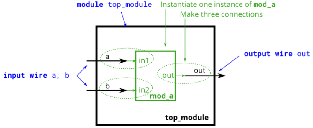
module top_module (input a, input b, output out)
	mod_a inst1 (a,b,out);
	//mod_a inst2 (.out(out), .in1(a), .in2(b));
endmodule
2. Connecting ports by position
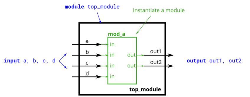
module top_module (
	input a,
	input b,
	input c,
	input d,
	output out1,
	output out2);
	mod_a inst1(out1,out2,a,b,c,d);
endmodule
3.Connecting ports by name
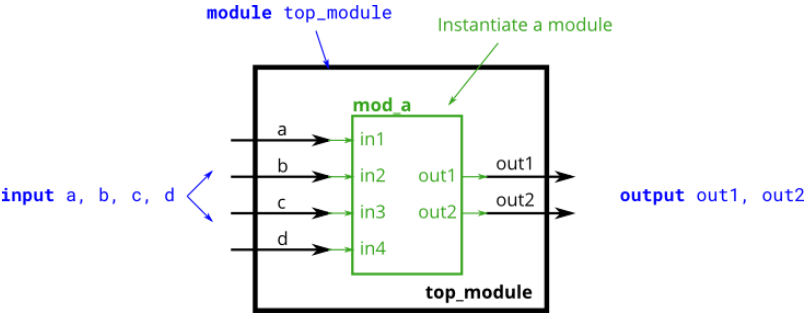
module top_module(
	input a,
	input b,
	input c,
	input d,
	output out1,
	output out2);
	mod_a inst1(.out1(out1), .out2(out2), .in1(a), .in2(b), .in3(c), .in4(d));
endmodule
4. Three modules
There is already a module my_dff, which has two inputs and one output (D trigger). Instantiate the three D triggers and connect them together to implement a shift register of length 3. clk port needs to be connected to all my_dff instance.
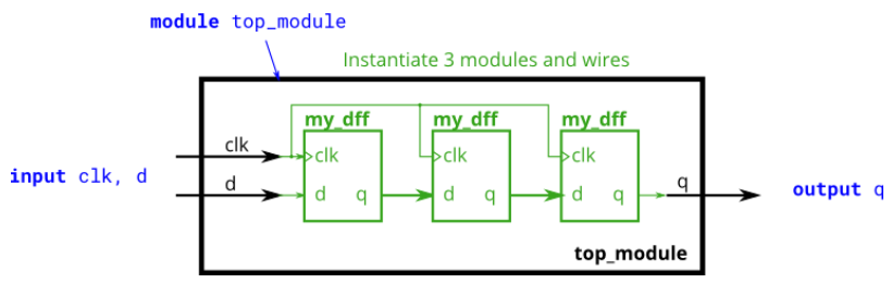
module top_module(input clk, input d, output q);
	wire w1,w2;
	my_dff inst1(.clk(clk), .d(d), .q(w1));
	my_dff inst2(.clk(clk), .d(w1), .q(w2));
	my_dff inst3(.clk(clk), .d(w2), .q(q));
endmodule
5.Modules and vectors
There is already a module my_dff8, which has two inputs and one output (implements a set of 8-bit D triggers). Instantiate three of them and then connect them together to implement an 8-bit wide shift register of length 3. In addition, a 4-1 multiplexer is constructed to select output values based on sel[1:0]. Essentially, selsels choose a period that delays input.
Existing module: module my_ Dff8 (input clk, input [7:0] d, output [7:0] q)
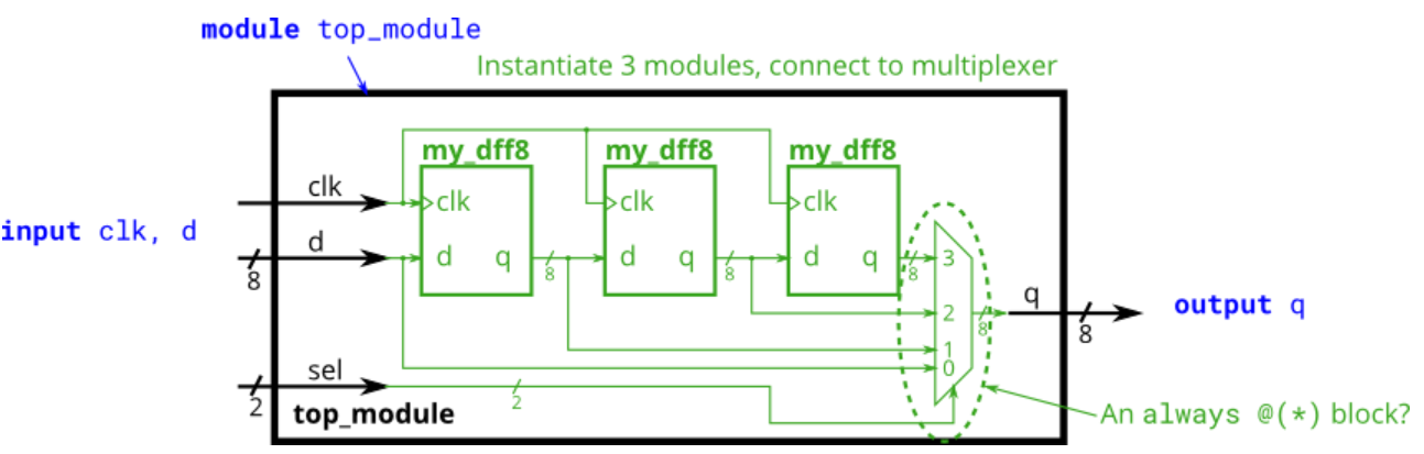
module top_module(
	input clk,
	input [7:0] d,
	input [1:0] sel,
	output [7:0] q);
	wire [7:0] w1,w2,w3;
	my_dff8 inst1(.clk(clk), .d(d), .q(w1));
	my_dff8 inst2(.clk(clk), .d(w1), .q(w2));
	my_dff8 inst3(.clk(clk), .d(w2), .q(w3));
	always@(*)begin
	case(sel)
		2'b00:q = d;
		2'b01:q = w1;
		3'b10:q = w2;
		4'b11:q = w3;
	endcase
	end
endmodule
6. Add1
Get a module that add16 performs 16-bit addition. Instantiate two of them to create a 32-bit adder. After receiving the carry from the first adder, one add16 module calculates the lower 16 bits of the addition result, while the second add16 module calculates the higher 16 bits. Your 32-bit adder does not need to process rounds (assume 0) or rounds (ignore), but the internal module does.
Existing modules: module add16 (input[15:0] a, input[15:0] b, input cin, output[15:0] sum, output cout);
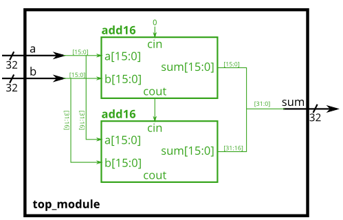
module top_module (
	input [31:0] a,
	input [31:0] b,
	output [31:0] sum);
	wire [15:0] low_out;
	wire [15:0] high_out;
	wire count1,count2;
	add16 low (a[15:0], b[15:0], 0, low_out, count1);
	add16 high (a[31:16], b[31:16], count1, high_out, count2);
	assign sum = {high_out, low_out};
endmodule
7. Add2
At top_ In module, two add16 modules are instantiated (provided to you), and 16 ADD1 instances are instantiated in each add16 (this module requires you to write). So you need to describe two modules: top_module and ADD1
Existing modules: module add16 (input[15:0] a, input[15:0] b, input cin, output[15:0] sum, output cout);
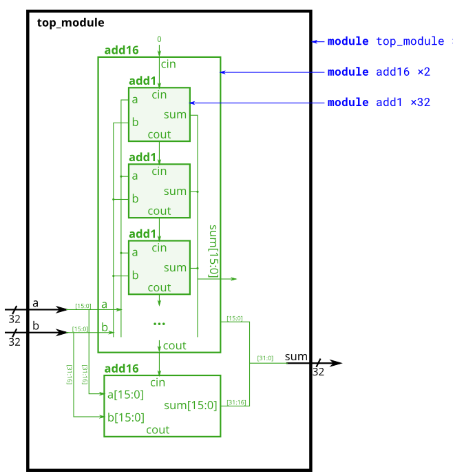
The logical expression of the full adder:
sum = a ^ b ^ cin;
count = (a&b)|(a&cin)|(b&cin);
module top_module(
	input [31:0] a,
	input [31:0] b,
	input [31:0] sum);
	wire count;
	add16 low ( a[15:0],  b[15:0], 0, sum[15:0], count );
	add16 high ( a[31:16],  b[31:16], count, sum[31:16]);
endmodule
module add1 (input a, input b, input cin, output sum, output cout);
	assign sum = a ^b ^ cin;
	assign cout = (a&b)|(a&cin)|(b&cin);
endmodule
8. Carry-select adder
Existing modules: module add16 (input[15:0] a, input[15:0] b, input cin, output[15:0] sum, output cout);
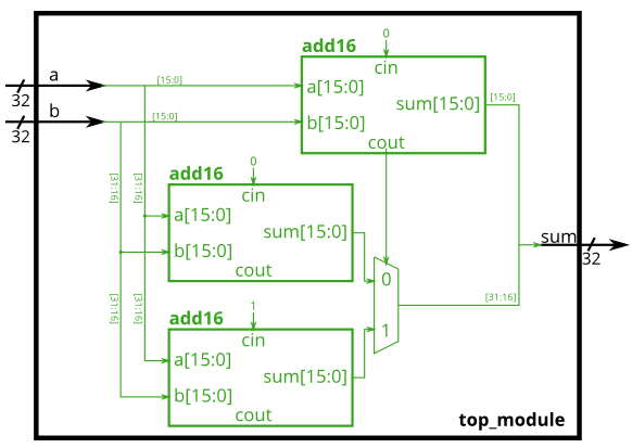
module top_module(
	input [31:0] a,
	input [31:0] b,
	output [31:0] sum);
	wire cout;
	wire [15:0] sum0,sum1;
	add16 low(a[15:0], b[15:0], 1'b0, sum[15:0], cout);
	add16 high1(a[31:16], b[31:16], 1'b0, sum0);
	add16 high2(a[31:16], b[31:16],1'b1, sum1);
	assign sum[31:16] = count?sum1:sum0;
endmodule
9.Adder-subractor
When sub1, the 32-bit XOR gate is used to reverse B.
XOR gates can also be viewed as programmable non-gates, where one input control should invert the other.
Existing modules: module add16 (input[15:0] a, input[15:0] b, input cin, output[15:0] sum, output cout);
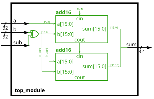
module top_module (
	input [31:0] a,
	input [31:0] b,
	input sub,
	output [31:0] sum);
	wire carry;
	wire [31:0] b_n;
	assign b_n = b ^ {32{sub}};
	add16 a0(a[15:0], b_n[15:0], sub, sum[15:0], carry);
	add16 a1(a[31:16], b_n[31:16], carry, sum[31:16]);
endmodule