1. Introduction of Network Virtualization Technology
1. What is a virtualized network
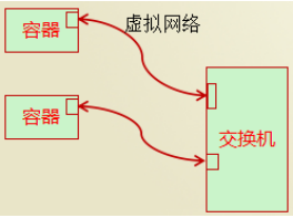
A virtualized network is a network virtualized by the linux kernel. In fact, the linux kernel can emulate a variety of network devices
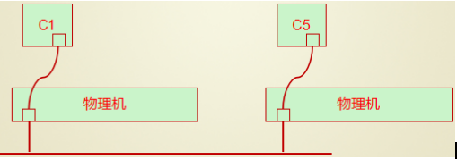
Analog network devices: Analog network devices appear in pairs, one in containers and one in switches
Analog switches: Containers are attached to this switch, and if IP is in the same network segment, they can communicate with each other as follows
There are many solutions for network virtualization, such as:
OVS
SDN
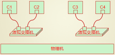
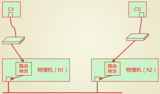
There can be multiple virtual switches on a physical machine, containers can be connected to different virtual switches, and if two virtual switches are not in the same network segment, how can they communicate?
Forwarding is required at this time
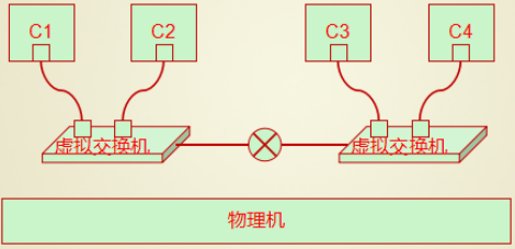
Kernel Forwarding Available
iptables forwarding is also available
2. How can containers on two physical machines communicate?
Method 1: Bridge mode (e.g. bridging of vmware)
In bridging mode, the physical network card will be used as a switch
All virtual machines are connected to the switches simulated by this physical network card
Then a network card is simulated for use by the physical machine, which is also plugged into the switch.
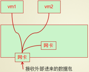
The physical machine network will determine the target mac when there are packets coming
If vm1, forward this packet to Vm1
If the physical machine has its own mac address, forward the message to the internal virtual network card
Containers on different hosts can communicate by bridging, that is, using a physical network card as a switch
Be careful:
Bridge mode is expensive, especially in a large-scale deployment scenario, and the result is that there will always be too many hosts in the network, resulting in storms.
Method 2:NAT mode
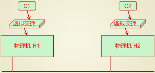
In nat mode scenarios, each container is still connected to a virtual switch, and the container's gateway needs to point to the address of the switch.
When a container generates a packet, the data is sent to the virtual machine switch
The virtual switch is emulated by the kernel, so this packet will be received by the kernel
The kernel checks to see if the target host is itself, and if not, it sends the packet from the network card, which completes the sending of the data.
Note: The problem at this point is that although data can be sent out, it won't come back
Because the source address of the packet sent by C is C1, and this address is hidden by the switch, other hosts in the network can't find this address, so they can't come back.
If you want the data to respond properly, you need to change the source address of the data package to the address of the H1 host and record the forwarding rule when sending the data package on the H1 host.
This way, when replying to the data, you only need to reply to the H1 host, which knows you need to forward this packet to C1 by checking the address translation table.
Each of these two approaches has its own problems
Bridging: Containers need to be exposed directly to the network. When there are too many containers, they form storms
NAT mode: Containers communicate based on NAT and need to translate addresses twice, which is too inefficient
Method 3: Overlay network, which is based on tunnel mode
In tunnel mode, you also need to simulate a switch, and the container is attached to the switch, as shown below
When sending data, instead of modifying the source ip source mac of the packet, an ip and mac layer is encapsulated on the basis of the original packet.
2. Docker Network Details
1. Docker's Three Networks
[root@host1 ~]# docker network ls
NETWORK ID          NAME                DRIVER              SCOPE
591c75b7dbea        bridge              bridge              local
386d8dc4beb8        host                host                local
eb7b7cf29f29        none                null                local
2. Bridge is the bridge mode
This bridge is not a bridge for a physical network card, but rather a software-only switch called docker0
Can be seen with ip addr or ip link show
[root@host1 ~]# ip addr
1: lo: <LOOPBACK,UP,LOWER_UP> mtu 65536 qdisc noqueue state UNKNOWN group default qlen 1000
  ...
2: ens33: <BROADCAST,MULTICAST,UP,LOWER_UP> mtu 1500 qdisc pfifo_fast state UP group default qlen 1000
  ...
3: ens37: <BROADCAST,MULTICAST,UP,LOWER_UP> mtu 1500 qdisc pfifo_fast state UP group default qlen 1000
  ...
4: docker0: <NO-CARRIER,BROADCAST,MULTICAST,UP> mtu 1500 qdisc noqueue state DOWN group default
    link/ether 02:42:a4:e8:44:11 brd ff:ff:ff:ff:ff:ff
    inet 172.17.0.1/16 brd 172.17.255.255 scope global docker0
       valid_lft forever preferred_lft forever
[root@host1 ~]# ip link show
1: lo: <LOOPBACK,UP,LOWER_UP> mtu 65536 qdisc noqueue state UNKNOWN mode DEFAULT group default qlen 1000
    link/loopback 00:00:00:00:00:00 brd 00:00:00:00:00:00
2: ens33: <BROADCAST,MULTICAST,UP,LOWER_UP> mtu 1500 qdisc pfifo_fast state UP mode DEFAULT group default qlen 1000
    link/ether 00:0c:29:3f:bf:cf brd ff:ff:ff:ff:ff:ff
3: ens37: <BROADCAST,MULTICAST,UP,LOWER_UP> mtu 1500 qdisc pfifo_fast state UP mode DEFAULT group default qlen 1000
    link/ether 00:0c:29:3f:bf:d9 brd ff:ff:ff:ff:ff:ff
4: docker0: <BROADCAST,MULTICAST,UP,LOWER_UP> mtu 1500 qdisc noqueue state UP mode DEFAULT group default
    link/ether 02:42:a4:e8:44:11 brd ff:ff:ff:ff:ff:ff
6: veth7c1728b@if5: <BROADCAST,MULTICAST,UP,LOWER_UP> mtu 1500 qdisc noqueue master docker0 state UP mode DEFAULT group default
    link/ether 9a:be:3b:60:d7:2e brd ff:ff:ff:ff:ff:ff link-netnsid 0
Start a container
[root@host1 ~]# docker run --rm --name vh1 -it busybox
/ #
The physical opportunity now has one more network card device
[root@host1 ~]# ip addr
1: lo: <LOOPBACK,UP,LOWER_UP> mtu 65536 qdisc noqueue state UNKNOWN group default qlen 1000
 ...
2: ens33: <BROADCAST,MULTICAST,UP,LOWER_UP> mtu 1500 qdisc pfifo_fast state UP group default qlen 1000
 ...
3: ens37: <BROADCAST,MULTICAST,UP,LOWER_UP> mtu 1500 qdisc pfifo_fast state UP group default qlen 1000
 ...
4: docker0: <BROADCAST,MULTICAST,UP,LOWER_UP> mtu 1500 qdisc noqueue state UP group default
    link/ether 02:42:a4:e8:44:11 brd ff:ff:ff:ff:ff:ff
    inet 172.17.0.1/16 brd 172.17.255.255 scope global docker0
       valid_lft forever preferred_lft forever
    inet6 fe80::42:a4ff:fee8:4411/64 scope link
       valid_lft forever preferred_lft forever
6: veth7c1728b@if5: <BROADCAST,MULTICAST,UP,LOWER_UP> mtu 1500 qdisc noqueue master docker0 state UP group default
    link/ether 9a:be:3b:60:d7:2e brd ff:ff:ff:ff:ff:ff link-netnsid 0
    inet6 fe80::98be:3bff:fe60:d72e/64 scope link
       valid_lft forever preferred_lft forever
This veth7c1728b@if5 is actually the part of the pair of network cards that are generated to connect to the docker0 Bridge
That is to understand that three containers insert network cables into the switch
The part in front of @ in the network card is the part connected to the virtual switch
The @back part of the network card is the container part
Look at the network card information in the container
/ # ip addr
brctl allows you to open and control and view the corresponding relationships between physical and container network cards
[root@host1 ~]# yum install bridge-utils -y
[root@host1 ~]# brctl show
bridge namebridge idSTP enabledinterfaces
docker08000.0242a4e84411noveth7c1728b
In fact, when using the Docker0 bridge, the system will automatically generate an iptables rule [POSTROUNTING rule]
[root@host1 ~]# iptables -L -n --line -t nat
Chain PREROUTING (policy ACCEPT)
num  target     prot opt source               destination
1    DOCKER     all  --  0.0.0.0/0            0.0.0.0/0            ADDRTYPE match dst-type LOCAL

Chain INPUT (policy ACCEPT)
num  target     prot opt source               destination

Chain OUTPUT (policy ACCEPT)
num  target     prot opt source               destination
1    DOCKER     all  --  0.0.0.0/0           !127.0.0.0/8          ADDRTYPE match dst-type LOCAL

Chain POSTROUTING (policy ACCEPT)
num  target     prot opt source               destination
1    MASQUERADE  all  --  172.17.0.0/16        0.0.0.0/0

Chain DOCKER (2 references)
num  target     prot opt source               destination
1    RETURN     all  --  0.0.0.0/0            0.0.0.0/0
There are three client sources for docker
Host: For example, access a Web site in a container on a host
Other containers on the same host: Two containers are connected to the same switch on the same physical machine and must be able to communicate
Containers on other hosts or other hosts: In this case, communication via nat or overlay networks is required
3. host mode
To isolate six classes of namespaces in a container
user
mount
pid
uts
net
ipc
Think about it: There are three containers, one that isolates only three namespace user mount pid s, and the other three that are shared by containers. What happens?
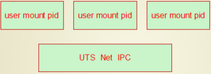
At this point, each container has its own file system, user information, and process information and is non-intrusive
However, the host name, network card and protocol stack of multiple containers are shared, that is, the host name and address are the same
This way, when one container accesses resources on another container, 12.0.0.1 is sufficient.
For example, if apache is installed in one container, mysql is installed in one container, and php is installed in the other, then these three hosts can communicate with each other based on 127 addresses, because they are using the same protocol stack.
Allow containers to share the namespace of physical machines
Containers share the physical machine's network card namespace, so if you modify the network card in the container, the physical machine's network card will be modified.
This pattern is the second type in the docker network: host, which is the network namespace where the container uses the host
4. NULL mode
The third category in docker networks: null
If the network of a container is set to a null network, that is to say, the container has no network. Sometimes you need to create a container that does not need to communicate with external hosts, you can do so.
5. Container Model Classification Diagram
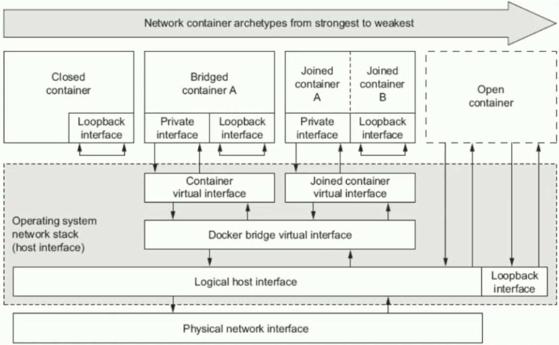
Close Model Container
bridged model container, which is a nat bridge, not a physical bridge, and the default mode
Federation Model Container (joined)
open Model Container
6. View network information when creating containers
Take a look at the bridged network model information
[root@host1 ~]# docker network inspect bridge
        ...
        ...
                    "Subnet": "172.17.0.0/16",
                    "Gateway": "172.17.0.1"
        ...
        ...
        ...
            "com.docker.network.bridge.name": "docker0",
        ...
View the network type of the container
[root@host1 ~]# docker container inspect vh1
        ...
        ...
        ...
        "NetworkSettings": {
            "Bridge": "",
        ...
        ...
        ...