DDS Direct Digital Synthesizer
The following is the code of generating sine wave, triangle wave and square wave with MATLAB, which can be used directly.
 1 t=0:2*pi/2^12:2*pi
 2 y=0.5*sin(t)+0.5;
 3 r=ceil(y*(2^8-1)); %Convert decimal to integer. ceil It's up.
 4 fid = fopen('sin.coe','w'); %write to sin.coe File, used for initialization sin_rom
 5 fprintf(fid,'MEMORY_INITIALIZATION_RADIX=10;\n');
 6 fprintf(fid,'MEMORY_INITIALIZATION_VECTOR=\n');
 7 for i = 1:1:2^12
 8 fprintf(fid,'%d',r(i));
 9 if i==2^12
10 fprintf(fid,';');
11 else
12 fprintf(fid,',');
13 end
14 if i%15==0
15 fprintf(fid,'\n');
16 end
17 end
18 fclose(fid);
19 t=1:1:2^12;
20 y=(t<=2047);
21 r=ceil(y*(2^8-1));
22 fid = fopen('square.coe','w'); %write to square.coe,Used for initialization rom_square
23 fprintf(fid,'MEMORY_INITIALIZATION_RADIX=10;\n');
24 fprintf(fid,'MEMORY_INITIALIZATION_VECTOR=\n');
25 for i = 1:1:2^12
26 fprintf(fid,'%d',r(i));
27 if i==2^12
28 fprintf(fid,';');
29 else
30 fprintf(fid,',');
31 end
32 if i%15==0
33 fprintf(fid,'\n');
34 end
35 end
36 fclose(fid);
37 t=1:1:2^12;
38 y=[0.5:0.5/1024:1-0.5/1024, 1-0.5/1024:-0.5/1024:0, 0.5/1024:0.5/1024:0.5];
39 r=ceil(y*(2^8-1));
40 fid = fopen('triangular.coe','w'); %write to triangular.coe,Initialization of triangular waves rom
41 fprintf(fid,'MEMORY_INITIALIZATION_RADIX=10;\n');
42 fprintf(fid,'MEMORY_INITIALIZATION_VECTOR=\n');
43 for i = 1:1:2^12
44 fprintf(fid,'%d',r(i));
45 if i==2^12
46 fprintf(fid,';');
47 else
48 fprintf(fid,',');
49 end
50 if i%15==0
51 fprintf(fid,'\n');
52 end
53 end
54 fclose(fid);
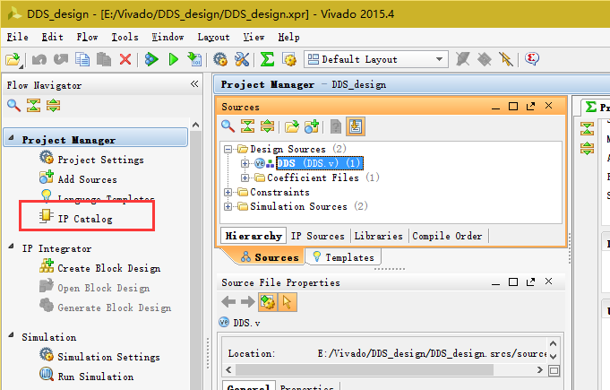
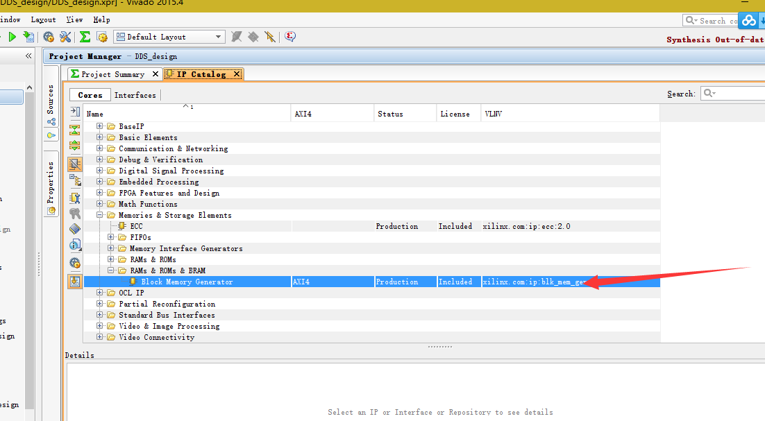
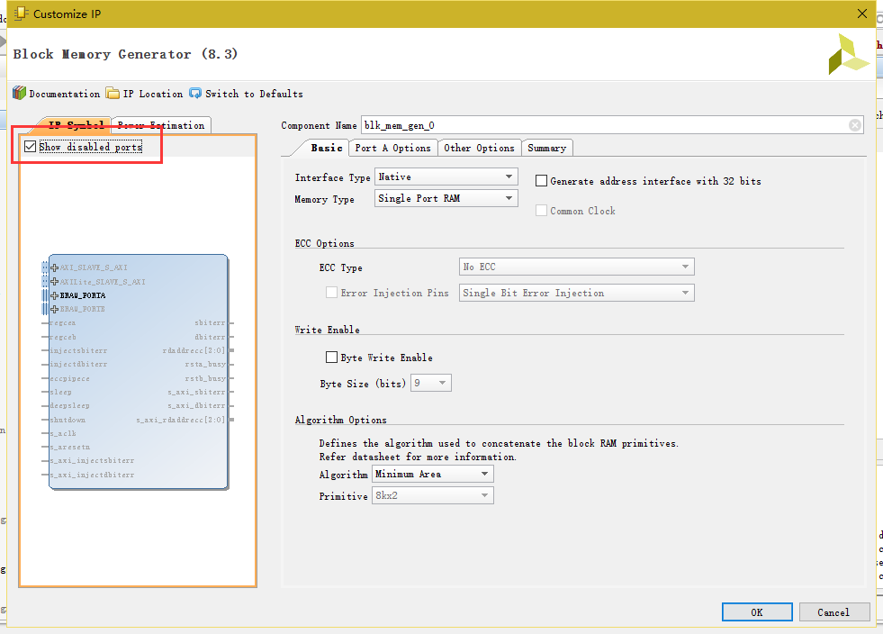
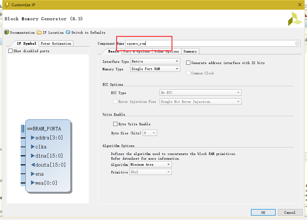
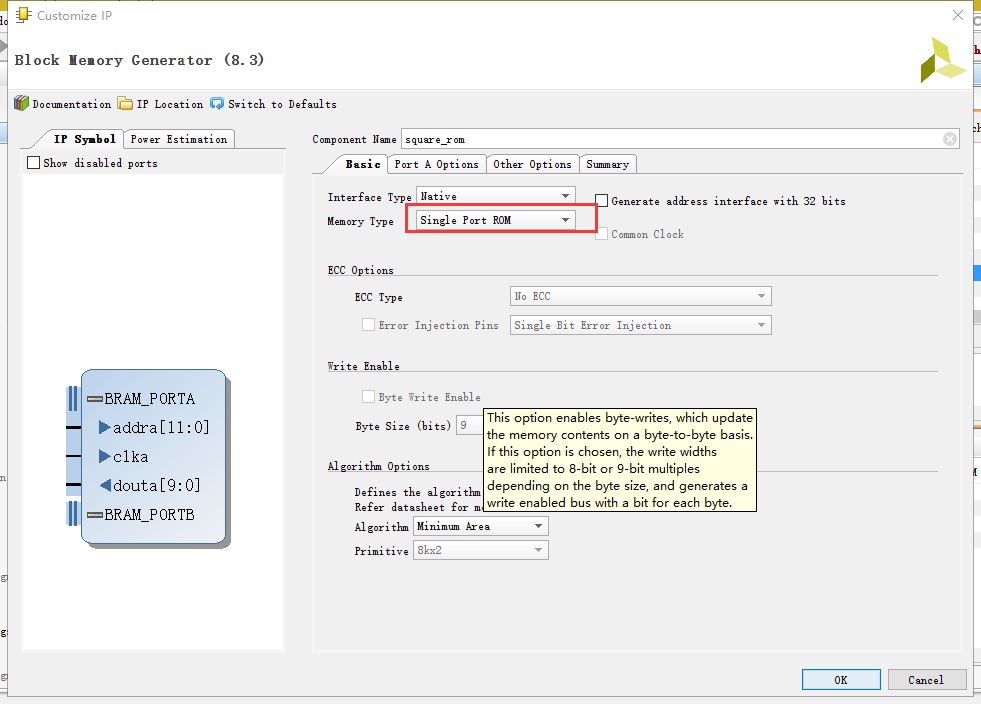
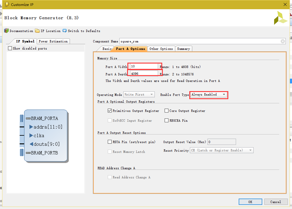
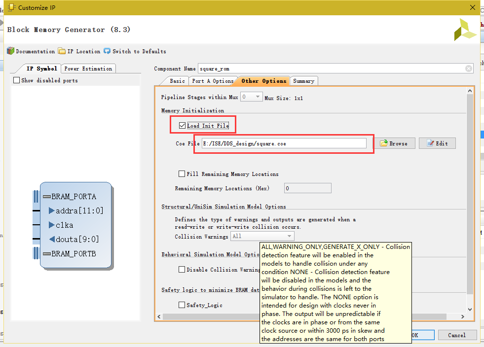
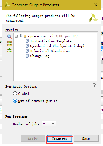
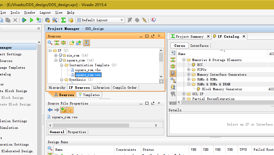
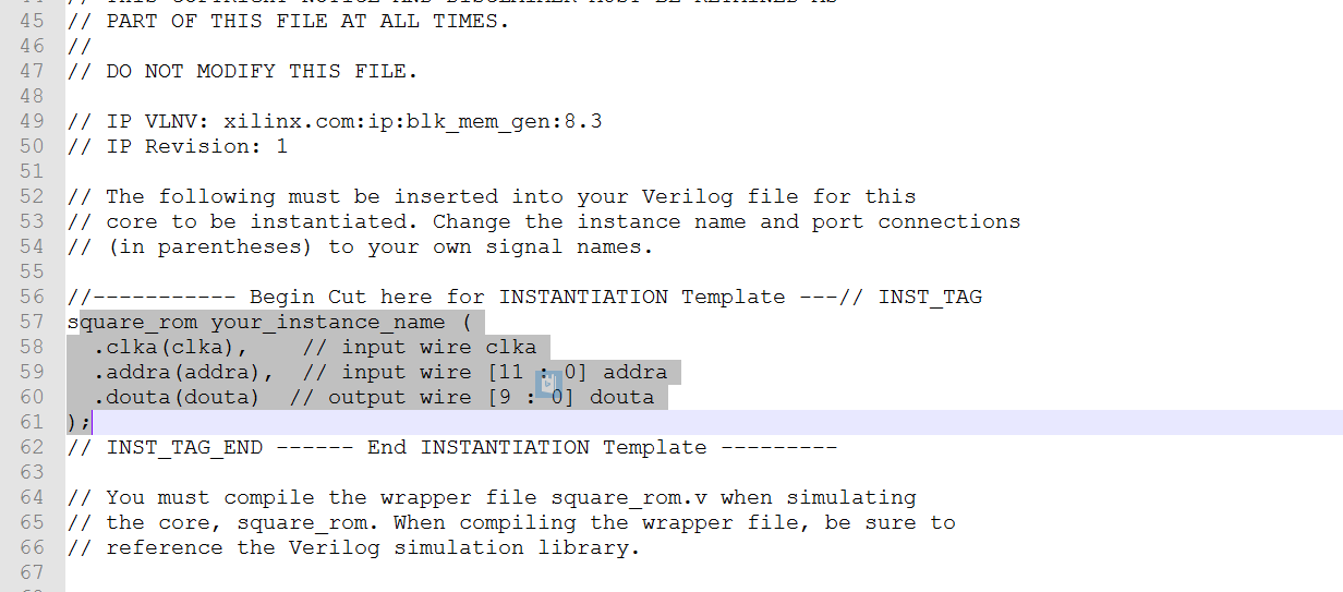
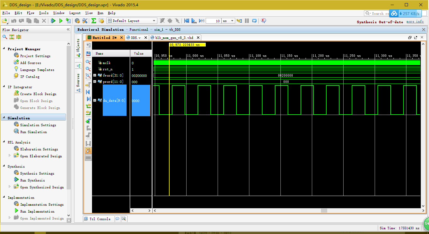
The core of DDS design is to call IP ROM. Viado calls ROM in a way similar to ISE. It loads. coe files. I take notes here to prevent forgetting.
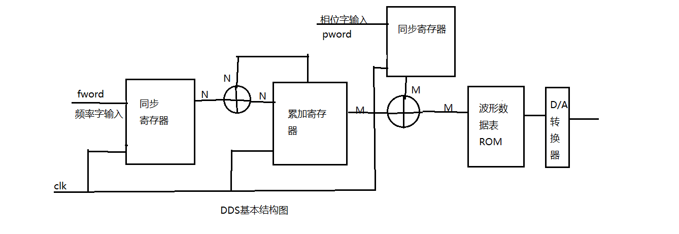
This is the principle diagram of DDS. DDS is not as abstruse as its name says. Its core is to control the frequency of fword input and phase word pword input. Finally, it can call IP verification to find tables. The code is very simple. Here is DDS design code.
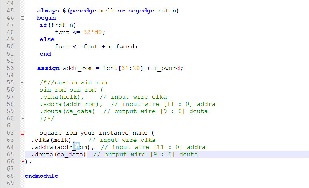
DDS_design 1 module DDS( 2 input mclk, 3 input rst_n, 4 input [31:0]fword,//frequency control 5 input [11:0]pword,//phase control 6 7 output [9:0]da_data 8 ); 9 10 reg [31:0]r_fword; 11 reg [11:0]r_pword; 12 reg [31:0]fcnt; 13 14 wire [11:0]addr_rom; 15 16 //Synchronization Register 17 always @(posedge mclk) 18 begin 19 r_fword <= fword; 20 r_pword <= pword; 21 end 22 23 always @(posedge mclk or negedge rst_n) 24 begin 25 if(!rst_n) 26 fcnt <= 32'd0; 27 else 28 fcnt <= fcnt + r_fword; 29 end 30 31 assign addr_rom = fcnt[31:20] + r_pword; 32 33 //custom sin_rom 34 sin_rom sin_rom ( 35 .clka(mclk), // input wire clka 36 .addra(addr_rom), // input wire [11 : 0] addra 37 .douta(da_data) // output wire [9 : 0] douta 38 ); 39 40 endmodule