In the computer 3D world, all object models are approximated and represented by polygon meshes, which can be triangles or quadrangles. Polygon mesh is the basic unit of object model. From the perspective of storage, the essence of 3D model is realized through vertices. In Direct3D, Vertex Buffer is used to store vertex data. Vertex data can be stored in memory or in the video memory of the graphics card. To illustrate the use of vertex buffers, let's take a look at an example of using vertex buffers to build a triangle. First, we create a project named "D3D_03_Triangle" using VS2019, and then create the "main.cpp" source file. At the same time, don't forget to change the value of "subsystem" from "console" to "window" in the "system" project under "linker", and add DirectX support, that is, add "include directory" and "Library Directory". Although it is cumbersome, these modifications are necessary. First, we still need to import header files. The code is as follows:
// Import header file
#include <windows.h>
#include <d3d9.h>
#include <d3dx9.h>
#include <string>

// Import dependent library files
#pragma comment(lib,"d3d9.lib")
#pragma comment(lib,"d3dx9.lib")

#define WINDOW_LEFT 		 two hundred 				//  window position
#define WINDOW_TOP 		 one hundred 				//  window position
#define WINDOW_WIDTH 	 eight hundred 				//  Window width
#define WINDOW_HEIGHT 	 six hundred 				//  Window height
#define WINDOW_TITLE 	 L"D3D game development" 	//  Window title
#define CLASS_NAME 		 L"D3D game development" 	//  Window class name

// Direct3D device pointer object
LPDIRECT3DDEVICE9 D3DDevice = NULL;

// Mouse position
int mx = 0, my = 0;
Before using Vertex Buffer to draw triangles, we need to define the structure of vertices. Here we only define the coordinates and colors of vertices, and then we declare a vertex cache object. The code is as follows:
// Define FVF flexible vertex format structure
struct D3D_DATA_VERTEX { FLOAT x, y, z, rhw; DWORD color; };

// D3DFVF_XYZRHW pixel coordinates (the upper left corner of the form is the origin of the coordinate system, and the coordinate unit is also a pixel). Projection transformation is not required
#define D3D_FVF_VERTEX (D3DFVF_XYZRHW | D3DFVF_DIFFUSE)

// Vertex Buffer Objects
LPDIRECT3DVERTEXBUFFER9 D3DVertexBuffer = NULL;
In the above, we defined a structure object and a vertex format macro. These two things are corresponding. X, y, z and RHW in the structure correspond to D3DFVF in the macro_ Xyzrhw, and the color in the structure corresponds to D3DFVF in the macro_ DIFFUSE. Diffuse is the diffuse color, that is, the color of the object. Note that the vertex type we define is D3DFVF_XYZRHW, which means that our vertex coordinates are the 2-dimensional coordinate system of the form. D3DFVF_XYZRHW is a homogeneous coordinate in the form of (x, y, z, w). Its coordinate value (x, y) is based on the form coordinate system. The origin (0,0) of the coordinate system is located in the upper left corner, and X is positive to the right and Y is positive to the down. Where z is the pixel depth, the value range is 0.0-1.0, the nearest place to the observer is 0.0, and the farthest visible place within the observation range is 1.0. W generally, only 1.0 can be used.
As we said before, 3D model drawing on 2D screen requires projection transformation. When 2D graphics are drawn on the 2D screen, because the dimensions are the same, they can be drawn directly without projection transformation. Relative to D3DFVF_XYZRHW type vertex, another D3DFVF_XYZ type, which is to draw 3D graphics, it needs projection transformation. D3DFVF_XYZRHW is usually used for UI (user interface) and D3DFVF_XYZRHW is gorod light, while D3DFVF_XYZ is lightless by default.
In the above vertex format macro, we simply build the vertex coordinate data and color data. In fact, we can define more, such as normal vector and texture coordinates. It should be noted that when writing the macro definition of flexible vertex format, we need to abide by an order principle. The order is the priority, which needs to be divided in this way:
Coordinate position > RHW value > blend weight value > normal vector > diffuse color value > specular color value > texture coordinates
Next, we continue to declare several functions to complete different functions. The code is as follows:
// Declare game start function (initialize DirectX)
bool startGame(HWND hwnd, HINSTANCE hInstance);

// Declare game end function (release object)
void endGame();

// Declare functions that handle user input in the game loop
void update(int type, WPARAM wParam);

// Declare the game interface rendering function in the game loop
void render(HWND hwnd);

// Declare window procedure function
LRESULT CALLBACK WndProc(HWND hwnd, UINT message, WPARAM wParam, LPARAM lParam);
The above functions have been used in the previous chapter and will not be described in detail here. We copied the wWinMain function, WndProc function and startGame function in the previous chapter. Here we need to use DirectX to draw triangles. There is no need to print text, so there is no need for D3DFont object. You can delete or comment it out. In this case, we do not need to process mouse and keyboard events, so the update method can be left blank.
// Define functions that handle user input in the game loop
void update(int type, WPARAM wParam) {};
Next, we'll copy the render function. Because we don't draw text, the code for drawing text can be deleted or commented out. The code is as follows:
// Define the game interface rendering function in the game loop
void render(HWND hwnd) {

	// Step 1: screen clearing operation
	D3DDevice->Clear(0,NULL,D3DCLEAR_STENCIL | D3DCLEAR_TARGET | D3DCLEAR_ZBUFFER,D3DCOLOR_XRGB(255, 255, 255),1.0f,0);

	// Step 2: start drawing
	D3DDevice->BeginScene();

	// Step 3: draw triangle

	// Step 4: end drawing
	D3DDevice->EndScene();

	// Step 5: display flip
	D3DDevice->Present(NULL,NULL,NULL,NULL);
}
Finally, we give the endGame function code as follows:
// Define game end function (release object)
void endGame() {

	D3DVertexBuffer->Release();
	D3DVertexBuffer = NULL;
	D3DDevice->Release();
	D3DDevice = NULL;
}
At this point, a clean DirectX program is ready. You can run it to ensure that the code copy and changes are correct. Because many codes are repeated and fixed, in order not to destroy these fixed codes, we redefine two new functions to initialize game data and draw game pictures, as follows:
// Declare initialization scene function
void initScene(HWND hwnd, HINSTANCE hInstance);

// Declare render scene functions
void renderScene(HWND hwnd);
The first function, initScene, must be called after the DirectX initialization. That is, before we instantiate the D3DFont object, at the end of the startGame function, the code is as follows:
// Step 5: release Direct3D interface object
D3D9->Release();
D3D9 = NULL;

// Initialize scene
initScene(hwnd, hInstance);
return true;
The second function renderScene is placed in the third step of the render function. The code is as follows:
// Step 2: start drawing
D3DDevice->BeginScene();

// Step 3: draw the scene
renderScene(hwnd);

// Step 4: end drawing
D3DDevice->EndScene();
The declaration and call of the two functions are completed. Next, we begin to define the first function initScene to draw the triangle. We know that a triangle consists of three vertices, so we need to provide the data of three vertices. As for the positions of these three vertices, we define them according to the form coordinate system. We also define the color of three vertices as red. In other words, the drawn triangle should be red. The code is as follows:
// Triangle vertex array, the upper left corner of the form is the coordinate origin, and the vertices start clockwise from the lower left
D3D_DATA_VERTEX vertexArray[] =
{
	{ 300.0f, 400.0f, 0.0f, 1.0f, D3DCOLOR_XRGB(255, 0, 0) },
	{ 400.0f, 200.0f, 0.0f, 1.0f, D3DCOLOR_XRGB(255, 0, 0) },
	{ 500.0f, 400.0f, 0.0f, 1.0f, D3DCOLOR_XRGB(255, 0, 0) },
};

// Create vertex buffer object
D3DDevice->CreateVertexBuffer(
	sizeof(vertexArray),	// Represents the byte size of vertex data
	0,					    // Indicates the use of cached additional information. The default is 0.
	D3D_FVF_VERTEX,	        // Represents a flexible vertex format
	D3DPOOL_DEFAULT,	    // Indicates the storage location of vertex cache, D3DPOOL_DEFAULT indicates that the video card is in the video memory
	&D3DVertexBuffer,		// Represents a vertex cache pointer object
	NULL);				    // Indicates a reserved parameter, which is set to NULL here

// Writes an array of triangle vertices to the vertex buffer object
void* ptr;
D3DVertexBuffer->Lock(
	0,					    // Indicates where to start locking (storage offset)
	sizeof(vertexArray),	// Indicates the number of bytes to be locked, that is, the size of the locked area
	(void**)&ptr,			// Pointer representing the locked storage area
	0);					    // Indicates the locking mode. Here we can set 0
// Assign vertex data to buffer
memcpy(ptr, vertexArray, sizeof(vertexArray));
D3DVertexBuffer->Unlock();
It should be noted here that locking and unlocking are required when writing vertex data to the vertex buffer object. These DirectX API parameters are basically given to you in the process of watching. You can understand them without further research. We need to know that we use three vertices to draw a triangle and put the vertex data into the vertex cache object. Next, we will complete the renderScene function and draw a triangle. The code is as follows:
D3DDevice->SetStreamSource(
	0,								// Represents the data stream connected to the vertex buffer. It can be 0 by default
	D3DVertexBuffer,				// Represents vertex buffer data
	0,								// Represents the offset in the data stream. It can be 0 by default
	sizeof(D3D_DATA_VERTEX));		// Represents the size of each vertex structure

D3DDevice->SetFVF(D3D_FVF_VERTEX);	// Format flexible vertices

D3DDevice->DrawPrimitive(
	D3DPT_TRIANGLELIST,	// Indicates the type of element to draw, D3DPT_TRIANGLELIST represents a list of triangles
	0,					// Specifies the starting index at which the vertex cache reads vertex data
	1);					// Number of triangle elements drawn
The drawing process is mainly completed by three functions. SetStreamSource is to set the drawing data to come from our vertex cache object. The SetFVF function is to format vertices. The DrawPrimitive function is to draw triangles. The effect of running the code is as follows:
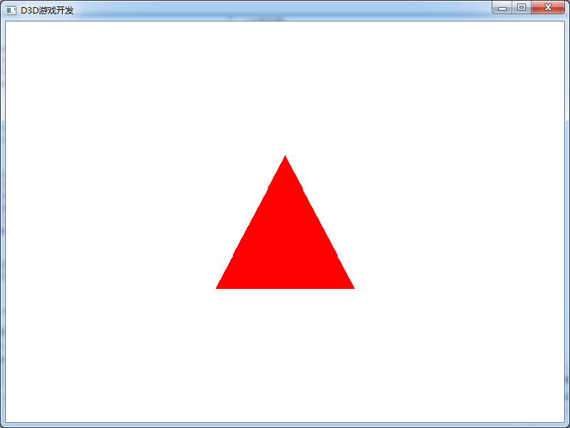
Why draw a triangle. Because in the game engine, 2D images and 3D models are composed of triangles.
Download address of all code cases of this course:
Note: This is the second course in our game development series. This course mainly uses C + + language and DirectX to explain some basic theoretical knowledge in game development. The learning goal is mainly based on understanding theoretical knowledge. The attached C + + code can be understood and run successfully. We are not required to use DirectX to develop games. If there are some mistakes in the course, please leave a message and correct them. Thank you very much!