Using lighting in 3D scene is very simple. We don't need to assign color values to each vertex of the model object. As long as we use some kind of lighting and set the material of the model object, Direct3D will calculate the color value of each vertex according to the lighting model algorithm to make the model produce color. As we have roughly introduced before, 3D models are completed in the modeling software, and materials are also given to the model. Therefore, in the actual game development, we only need to load the model file, read the material, and set the material for the model when rendering the model. Then, under the illumination of the light source, the model will display its own color. Generally, we don't use vertices to build a model manually. We use vertices to build a quadrilateral. This situation is mostly used for GUI user interface and 2D game development. At the same time, we don't assign colors to vertices. Basically, we paste a picture on this quadrilateral, that is, texture mapping. Modeling and texture mapping belong to art workers. Program developers mainly load the model and map files into the game after they get them.
There are two concepts about lighting. We must distinguish them. One is the type of illumination and the other is the type of light source. The types of lighting have been roughly mentioned before. They can be divided into ambient light, diffuse light and specular light (highlight). The types of light sources are divided into Point Light, Directional Light and Spot Light. In fact, there is no conflict between the two. The former is classified according to the lighting structure, and the latter is classified according to the lighting area. Whether Point Light, Directional Light, or spotlight, they are composed of ambient light, diffuse light and highlight.
First, introduce the lighting type. Ambient light means that a model object can be seen as long as light (reflected by other objects) reaches the object, even if there is no direct light source. This overall brightness based on the whole natural environment is called ambient light. Ambient light has no characteristics of position or direction, only one color brightness value, and will not decay. In other words, ambient light is a concept of global light. If you want to simulate lighting at a low cost and cost, it is a good choice to turn on the ambient light directly. The setting code of ambient light in Direct3D is as follows:
D3DDevice->setRenderState(D3DRS_AMBIENT, D3DCOLOR_XRGB(255,255,255));
Diffuse light is the most common, and the illumination of sunlight and light can be regarded as diffuse light. This type of light propagates in a specific direction, reaches the object surface and reflects evenly in all directions. Therefore, the color and brightness are the same no matter which direction you look at the object from. Generally, the color of the model is basically determined by the diffuse light.
Specular reflected light (high light), this type of light propagates in a specific direction. When it reaches the object surface, it will be reflected in one direction, resulting in high brightness illumination that can only be observed in an angle range. It should be noted that compared with other types of light, specular light requires a lot of calculation. Direct3D turns off specular reflection by default. If you want to turn on specular emission, you can use the following code:
D3DDevice->SetRenderState(D3DRS_SPECULARENABLE, true);
In addition, there is also an Emissive Light, which is the light emitted by the model itself. It is realized through the self luminous material of the object. The material emissivity of the object describes the color and transparency of self illumination. Its purpose is not to irradiate the model object through the light source, but to make the model object appear brighter, and the self illumination will not have any illumination impact on the surrounding objects, that is, the self illumination does not participate in the calculation of the illumination model.
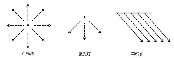
The above is the lighting type, and the following is the light source type. Direct3D mainly has three types of light sources, Point Light, Directional Light and Spot Light.
Point lights have color and position attributes and emit light in all directions. The light emitted evenly from one point to the surrounding has the largest illumination range, and the brightness decreases with distance. The most obvious example is the bulb used in our home. Because a point light attenuates, it is a local light source that illuminates only part of the area.
Directional light source is a group of parallel and uniform light emitted from infinity. It propagates in the same direction in the scene, has color and direction attributes, and is also not affected by distance attenuation. Directional light is a group of directional light without attenuation, similar to the effect of sunlight. Directional light is also a kind of global light.
A spotlight light source is similar to a searchlight. The light emitted by the spotlight is similar to a cone (inner and outer vertebral bodies). The light emitted by it will decay with distance, and the inner vertebral body will decay to the outer vertebral body. Because the spotlight is affected by attenuation, the computational performance overhead of its corresponding lighting model is higher, so the use of spotlight should be avoided as far as possible. A spotlight is a local light source.
In DirectX, the D3DLIGHT9 structure is used to represent a light source object. The structure contains the type of light source and the color value of light. For local light sources, it is also necessary to set an attenuation range value. The settings of these parameters are user-friendly. We will introduce them in detail in the code case. Next, let's talk about a material. In DirectX, D3DMATERIAL9 structure is used to represent a material object, and its parameters are basically the setting of reflectivity. Next, we use VS2019 to create a new project "D3D_05_Light", and then copy the previous code. In order to better plan our code, we store the light source settings independently in the new method initLight. Because the setting of light is basically one-time, we put the initLight function in the initScene function.
The following is the declaration of global variables:
// Direct3D device pointer object
LPDIRECT3DDEVICE9 D3DDevice = NULL;

// Mouse position
int mx = 0, my = 0;

// Teapot model object
LPD3DXMESH D3DTeapt;
Next is our initScene function. The code is as follows:
// Initialize teapot model
D3DXCreateTeapot(D3DDevice, &D3DTeapt, NULL);

// Initialize projection transformation
initProjection();

// Initialize lighting
initLight();
In the initProjection function, we fix three types of transformations. The code is as follows:
// Set viewfinder transformation matrix
D3DXMATRIX viewMatrix;
D3DXVECTOR3 viewEye(0.0f, 2.0f, -3.0f);	    // Camera position
D3DXVECTOR3 viewLookAt(0.0f, 0.0f, 0.0f);	// Position of observation point
D3DXVECTOR3 viewUp(0.0f, 1.0f, 0.0f);		// Upward vector
D3DXMatrixLookAtLH(&viewMatrix, &viewEye, &viewLookAt, &viewUp);
D3DDevice->SetTransform(D3DTS_VIEW, &viewMatrix);


// Set perspective projection transformation matrix
D3DXMATRIX projMatrix;
float angle = D3DX_PI * 0.5f; // 90 degrees
float wh = (float)WINDOW_WIDTH / (float)WINDOW_HEIGHT;
D3DXMatrixPerspectiveFovLH(
	&projMatrix,	// Represents the projection transformation matrix
	angle,		    // Represents the field of view angle of the camera
	wh,			    // Represents the aspect ratio of the screen display area
	1.0f,			// Represents the near clipping plane in the viewport
	1000.0f);		// Represents the far clipping plane in the viewport
D3DDevice->SetTransform(D3DTS_PROJECTION, &projMatrix);

// Set viewport transformations
D3DVIEWPORT9 viewport = {
	0,				// The X coordinate of the viewport relative to the window, which is 0 by default
	0,				// The Y coordinate of the viewport relative to the window is 0 by default
	WINDOW_WIDTH,	// The width of the viewport
	WINDOW_HEIGHT,  // The height of the viewport
	0,				// The minimum depth value of the viewport in the depth cache, which is 0 by default
	1				// The maximum depth value of the viewport in the depth cache, which is 1 by default
};
D3DDevice->SetViewport(&viewport);
Next is our initLight function. We introduce the creation of different light sources one by one. The code is as follows:
// Point source
D3DLIGHT9 pointLight;
::ZeroMemory(&pointLight, sizeof(pointLight));
pointLight.Type = D3DLIGHT_POINT;				            // Indicates the type of light source
pointLight.Ambient = D3DXCOLOR(0.0f, 0.0f, 0.0f, 0.0f);	    // Represents the ambient color value
pointLight.Diffuse = D3DXCOLOR(1.0f, 1.0f, 1.0f, 0.0f);	    // Represents the diffuse color value
pointLight.Specular = D3DXCOLOR(0.0f, 0.0f, 0.0f, 0.0f);    // Represents the specular color value
pointLight.Position = D3DXVECTOR3(0.0f, 10.0f, 0.0f);       // Represents the position of the light source, 10 units above the Y axis of the world origin
pointLight.Attenuation0 = 0.0f;	// Constant attenuation coefficient, usually 0.0f
pointLight.Attenuation1 = 0.1f;	// The linear attenuation coefficient, usually 1.0f, here we use 0.1
pointLight.Attenuation2 = 0.0f;	// Secondary attenuation coefficient, usually 0.0f
pointLight.Range = 1000.0f;	    // The maximum range that light can travel
D3DDevice->SetLight(0, &pointLight);
D3DDevice->LightEnable(0, true);
All light sources are D3DLIGHT9 structures, and different light source types are distinguished by the same Type. All light sources have settings for ambient color values, diffuse color values, and specular color values. For a point light source, we also need to set the position and the maximum range of propagation, which can be understood as a sphere. Also set a attenuation of the point light source. The farther the distance, the more severe the attenuation of the light source. The following is the attenuation formula with distance:
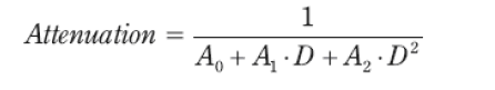
Attenuation0 is usually 0.0f, Attenuation1 is usually 1.0f, Attenuation2 is usually 0.0f, D represents the distance to the light source, and attenuationis the final calculated attenuation value. In this case, our distance is very small, so we can set Attenuation1 to 0.1. On the attenuation problem, we can understand it. After defining the D3DLIGHT9 structure, you can use the light source in the scene by calling SetLight and LightEnable methods. The SetLight function has two parameters. The first parameter is the index ID of the light source, the second parameter is the D3DLIGHT9 structure just built, and the LightEnable function also has two parameters. The first parameter is the index ID of the light source, the second parameter is boolean type, true means to enable the light source, and false means to disable the light source. Let's take a look at the effect of this point light on the teapot:
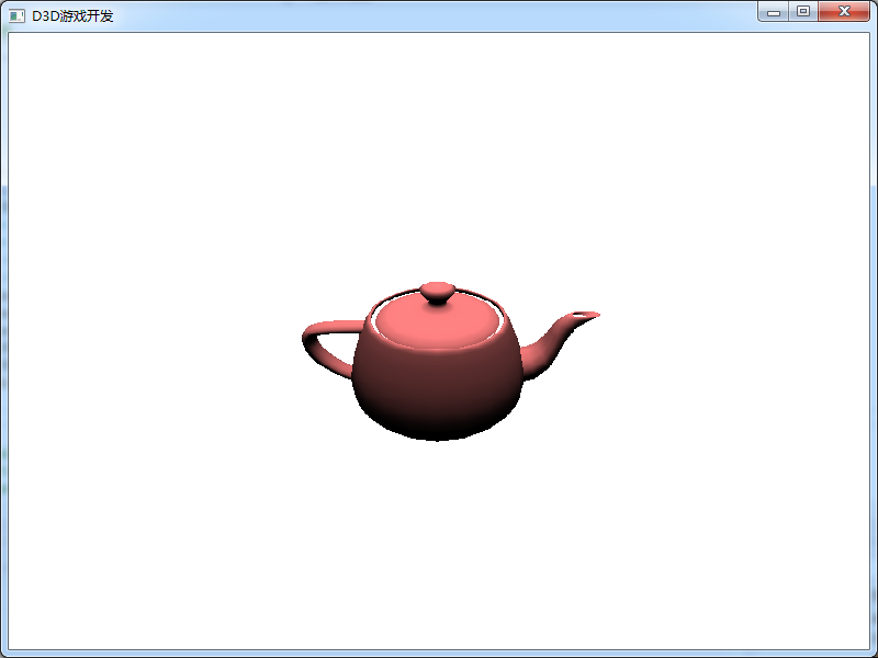
We can see that the point light source is directly above the teapot (the world origin), and then illuminates the scene within 1000 units around. We set the teapot to reflect the red color, so the teapot displays red. There is no light at the bottom of the teapot, so it is black. Next, we define a directional light to illuminate the whole scene from right to left in the X-axis direction.
// Parallel light
D3DLIGHT9 directionalLight;
::ZeroMemory(&directionalLight, sizeof(directionalLight));
directionalLight.Type = D3DLIGHT_DIRECTIONAL;		            // Indicates the type of light source
directionalLight.Ambient = D3DXCOLOR(0.0f, 0.0f, 0.0f, 0.0f);	// Represents the ambient color value
directionalLight.Diffuse = D3DXCOLOR(1.0f, 1.0f, 1.0f, 0.0f);	// Represents the diffuse color value
directionalLight.Specular = D3DXCOLOR(0.0f, 0.0f, 0.0f, 0.0f);	// Represents the specular color value
directionalLight.Direction = D3DXVECTOR3(-1.0f, 0.0f, 0.0f);	// Indicates the irradiation direction and propagates in the negative X direction (from right to left)
D3DDevice->SetLight(1, &directionalLight);
D3DDevice->LightEnable(1, true);
The above defines a directional light, which has only one unique parameter, that is, the direction of illumination. Similarly, we need to use SetLight and LightEnable to enable this directional light. The index of the directional light is 1, and the index of the previous point light source is 0. We must distinguish this. In this case, we let the directional light shine from the right to the left, then the right side of the teapot will be very bright and the lower left will be darker. Directional light has no attenuation. It can illuminate all objects in the scene. Therefore, it barely counts as a global light. However, it is different from the real ambient global light. The ambient global light will illuminate all objects in the scene from all directions, so it will not produce dark parts for objects. Let's look at the effect of directional light:
We can see that the right side of the teapot lights up because it receives a parallel light from the right. Next, we continue to create a spotlight. We let the spotlight shine from left to right. The code is as follows:
// Spotlight
D3DLIGHT9 spotLight;
::ZeroMemory(&spotLight, sizeof(spotLight));
spotLight.Type = D3DLIGHT_SPOT;					        // Indicates the type of light source
spotLight.Ambient = D3DXCOLOR(0.0f, 0.0f, 0.0f, 0.0f);	// Represents the ambient color value
spotLight.Diffuse = D3DXCOLOR(1.0f, 1.0f, 1.0f, 0.0f);	// Represents the diffuse color value
spotLight.Specular = D3DXCOLOR(0.0f, 0.0f, 0.0f, 0.0f);	// Represents the specular color value
spotLight.Position = D3DXVECTOR3(-10.0f, 0.0f, 0.0f);   // Represents the position of the light source, 10 units to the left of the X axis of the world origin
spotLight.Direction = D3DXVECTOR3(1.0f, 0.0f, 0.0f);    // Indicates the irradiation direction and propagates in the positive X direction (from left to right)
spotLight.Attenuation0 = 0.0f;		// Constant attenuation coefficient, usually 0.0f
spotLight.Attenuation1 = 0.1f;		// The linear attenuation coefficient, usually 1.0f, here we use 0.1
spotLight.Attenuation2 = 0.0f;		// Secondary attenuation coefficient, usually 0.0f
spotLight.Range = 1000.0f;		    // The maximum range that light can travel
spotLight.Falloff = 0.1f;			// The intensity attenuation of light from the inner cone to the outer cone is usually set to 1.0f
spotLight.Phi = D3DX_PI / 2.0f;		// Specifies the angle of the outer cone of the spotlight, in radians, which we set to 90 degrees
spotLight.Theta = D3DX_PI / 4.0f;	// Specifies the angle of the cone in the spotlight, in radians, which we set to 45 degrees
D3DDevice->SetLight(2, &spotLight);
D3DDevice->LightEnable(2, true);
The above is the definition of a spotlight, which has many parameters. Because the spotlight is an inner and outer cone, its position, direction, propagation distance and radian of the inner and outer cone need to be set. You also need to set its attenuation. In addition to the distance factor, the attenuation of the spotlight also needs to set the attenuation of the inner cone to the outer cone. After the definition is completed, you also need to use SetLight and LightEnable methods to enable the directional light. Let's look at the effect after adding a spotlight:
We can see that the teapot is illuminated from the top, left and right. Although we have defined the ambient color value (all zero) in the three types of light sources, the real ambient effect is set as follows:
// Set the ambient light
D3DDevice->SetRenderState(D3DRS_AMBIENT, D3DCOLOR_XRGB(255, 255, 255));
So, doesn't setting ambient light in the above three light sources work? The answer, it works. However, you can't set two types of ambient lights at the same time, which will cause problems. Generally, we do not set the ambient light in the light source, but directly use the above code to uniformly set the ambient light color value. The simplest and best way to use light sources to illuminate the scene is to set the ambient light, which is actually a directional light, a point light, and finally a spotlight. As we mentioned before, the lighting model consumes a lot of hardware performance. However, different lighting combinations will simulate the real light and shadow effect and increase the user's experience. Therefore, the use of lighting in the scene is still determined according to the design requirements of the game. In this case, we have not set the highlight effect, because the highlight effect also needs the support of hardware performance.
Finally, in order to ensure the use of lighting, we also need to turn on lighting. The code is as follows:
// Turn on the light
D3DDevice->SetRenderState(D3DRS_LIGHTING, true);
After the introduction of lighting, let's set a default material. In fact, in game development, different models will have different materials. This case only demonstrates the lighting effect, so just make a default material. As mentioned above, we can make a material that reflects red light and give it to the model in the scene. The code is as follows:
// Set default material
D3DMATERIAL9 defaultMaterial;
::ZeroMemory(&defaultMaterial, sizeof(defaultMaterial));
defaultMaterial.Ambient = D3DXCOLOR(1.0f, 0.5f, 0.5f, 0.0f);	// Ambient light reflection: 100% red light, 50% green light and 50% blue light
defaultMaterial.Diffuse = D3DXCOLOR(1.0f, 0.5f, 0.5f, 0.0f);	// Diffuse reflection: 100% red, 50% green and 50% blue
defaultMaterial.Specular = D3DXCOLOR(0.0f, 0.0f, 0.0f, 0.0f);	// Non reflective highlights
defaultMaterial.Emissive = D3DXCOLOR(0.0f, 0.0f, 0.0f, 0.0f);	// Non self luminous
defaultMaterial.Power = 0.0f;							        // No highlights
D3DDevice->SetMaterial(&defaultMaterial);
We can use D3DXCOLOR(R, G, B, A) to represent the material reflection color value (D3DCLORVALUE), where R, G, B and a represent the component values of red, green, blue and transparency between 0.0f and 1.0f respectively. 0 represents the color light that does not reflect the component, and 1 represents all the color light that reflects the component. After defining the structure of D3DMATERIAL9, we need to call the SetMaterial method to set the currently used material. In addition, if the material is not specified by code in the program, Direct3D has a default material. The default material reflects all diffuse light, but does not reflect ambient light and specular emission light, and has no self luminous color. So far, our initLight function has been completed. Here, we do not set user interaction events, so the update function is empty. The rest is the renderScene function, which contains the following code:
// Draw teapot
D3DTeapt->DrawSubset(0);
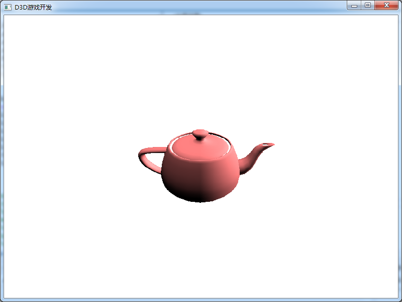
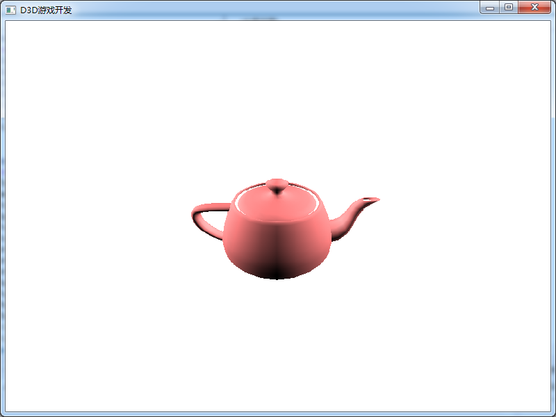
Finally, we can run the code and see the real effect of the teapot, because we have added the global ambient light, so all parts of the teapot will become bright. The effect is shown in the following figure:
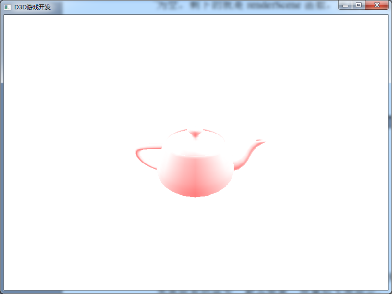
Because of the addition of global illumination, the overall red of the teapot is brighter. If we only turn on the global ambient light, the effect of removing other light sources is as follows:

The global ambient light shines on the teapot from all directions at the same time, so that the color of its surface is the same, and there is no light and shadow effect.
In the lighting model, there is also a concept of normal, which determines the direction of reflected light. Each face has its own normal. In 3D game, a triangle represents a face. The face normal is easy to understand, that is, a normal perpendicular to the triangular face. The face normal can find two edges through its three points, and then cross multiply the two edges to obtain the face normal. Where does the vertex normal come from? Strictly speaking, from the definition of normal, in fact, there is no vertex normal. Why is there the concept of vertex normal. Let the vertices also have normals, so that the incident angle of incident light reaching the surface can be calculated during illumination calculation, and a smooth effect can be obtained on the surface of polyhedron. Generally, vertex normals and face normals are the same, but in some approximate spherical surfaces (smooth surfaces), vertex normals and face normals are inconsistent. If the vertex normals are not used, the lighting calculation of the three vertices of a triangular face is calculated according to the face normals of its face. Because the normals of the three vertices are the same, the three vertices will obtain the same lighting effect. Such light causes no color transition between faces, which is very stiff. If vertex normals are used, the normals of three vertices of the same face are not necessarily the same, and a smooth transition lighting effect can be obtained on the surface of polyhedron. Vertex normals are the average normals obtained by adding the normals of several faces sharing the vertex and dividing them by the number of faces. This is the vertex normals. To put it bluntly, the vertex normal is to let a large number of triangles approach the simulated smooth surface, and the color is smooth transition, which looks natural and real. If we calculate vertex normals manually, we need to normalize (normalize) vertex normals!
Download address of all code cases of this course:
Note: This is the second course in our game development series. This course mainly uses C + + language and DirectX to explain some basic theoretical knowledge in game development. The learning goal is mainly based on understanding theoretical knowledge. The attached C + + code can be understood and run successfully. We are not required to use DirectX to develop games. If there are some mistakes in the course, please leave a message and correct them. Thank you very much!