Motion Control
A simple FOC library has two main parameters that define the motion control architecture to use (and each parameter can be modified in real time):
- Torque Control Mode-motor.torque_controller
- Motion Control Mode - motor.controller
- Closed-loop motion control -with position sensor
- Open-loop motion control - No location sensor
Torque Control Mode
Three types of torque control are implemented in the Simple FOC library:
- Voltage - TorqueControlType::voltage
- DC Current - TorqueControlType::dc_current
- FOC Current - TorqueControlType::foc_current
And you can set their torque_controller by changing the motor properties.
// set torque mode to be used
// TorqueControlType::voltage    ( default )
// TorqueControlType::dc_current
// TorqueControlType::foc_current
motor.torque_controller = TorqueControlType::foc_current;
A more in-depth explanation of the different torque modes
Torque Control Mode
The simple FOC library gives you the option to use three different torque control strategies:
- Voltage mode-voltage
- DC Current Mode-dc_current
- FOC Current Mode-foc_current
1.Voltage mode - voltage
Torque control by voltage is the most basic type of torque control. It provides you with an abstraction of the BLDC motor so that you can control it as a DC motor. It is based on the principle that current is proportional to voltage (ignoring current dynamics), so no current detection hardware is required. For more information about this method, please visit our Deep Digging Section This torque control method will be able to work on any BLDC driver board, regardless of whether it has current induction.
Torque control using voltage
This torque control method allows you to run the BLDC motor because it is a simple DC motor where the target motor voltage Uq and FOC algorithms are set to calculate the required phase voltage ua, ub and uc for smooth operation. This mode is enabled by:
// voltage torque control mode
motor.torque_controller = TorqueControlType::voltage;
How it works
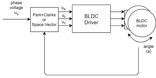
The voltage control algorithm reads angle a from the position sensor and obtains the target U q voltage value from the user, and uses the FOC algorithm to set the appropriate u a, u b and u c voltage for the motor. The FOC algorithm ensures that these voltages generate a magnetic force 90 degrees offset from the permanent magnet magnetic field in the motor rotor, thereby guaranteeing the maximum torque, which is called commutation.
It is assumed that the torque generated in the motor is proportional to the voltage because Uq is set by the user r. The maximum torque corresponds to the maximum Uq determined by the available power supply voltage, and the minimum torque is of course Uq = 0.
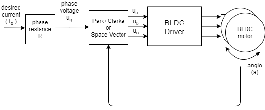
If the user provides the value of the phase resistance of the motor, the user can set the required current Id, and the library will automatically calculate the appropriate voltage Uq. This can be done by, for example, a constructor
// BLDCMotor(pole pair number, phase resistance)
BLDCMotor motor = BLDCMotor( 11, 2.5 );
Or just set parameters:
motor.phase_resistance = 2.5; // ex. 2.5 Ohms
configuration parameter
This control loop is very basic and does not actually have any configuration parameters.
Torque Control Sample Code
A simple example of voltage-based torque control and setting the target current through a serial command interface.
#include <SimpleFOC.h>

// BLDC motor & driver instance
BLDCMotor motor = BLDCMotor(11);
BLDCDriver3PWM driver = BLDCDriver3PWM(9, 5, 6, 8);

// encoder instance
Encoder encoder = Encoder(2, 3, 500);
// channel A and B callbacks
void doA(){encoder.handleA();}
void doB(){encoder.handleB();}

// instantiate the commander
Commander command = Commander(Serial);
void doTarget(char* cmd) { command.variable(&motor.target, cmd); }

void setup() {

  // initialize encoder sensor hardware
  encoder.init();
  encoder.enableInterrupts(doA, doB);
  // link the motor to the sensor
  motor.linkSensor(&encoder);

  // driver config
  // power supply voltage [V]
  driver.voltage_power_supply = 12;
  driver.init();
  // link driver
  motor.linkDriver(&driver);

  // set the torque control type
  motor.phase_resistance = 12.5; // 12.5 Ohms
  motor.torque_controller = TorqueControlType::voltage;
  // set motion control loop to be used
  motor.controller = MotionControlType::torque;

  // use monitoring with serial
  Serial.begin(115200);
  // comment out if not needed
  motor.useMonitoring(Serial);

  // initialize motor
  motor.init();
  // align sensor and start FOC
  motor.initFOC();

  // add target command T
  command.add('T', doTarget, "target current");

  Serial.println(F("Motor ready."));
  Serial.println(F("Set the target current using serial terminal:"));
  _delay(1000);
}

void loop() {

  // main FOC algorithm function
  motor.loopFOC();

  // Motion control function
  motor.move();

  // user communication
  command.run();
}
==================================================================================================================================================
2.DC Current Mode - dc_current
The DC current control mode allows you to control the current of the BLDC motor just as you control the DC motor. Current sensing is used to obtain the overall size of the current drawn by the motor and its direction, and assumes that the torque is proportional to the total current. The advantage of this method is that the real current set to the BLDC motor can be controlled very accurately, and for low-performance Microcontrollers(e.g. Atmega328 series) is faster and more stable to execute.
Torque control using DC current
This control loop allows you to run the BLDC motor because it is a current-controlled DC motor. This torque control algorithm requires current detection hardware. Users set the target current Id to the FOC algorithm, which calculates the necessary phase voltage ua, ub and uc to maintain operation. This mode is enabled by:
// DC current torque control mode
motor.torque_controller = TorqueControlType::dc_current;
How it works
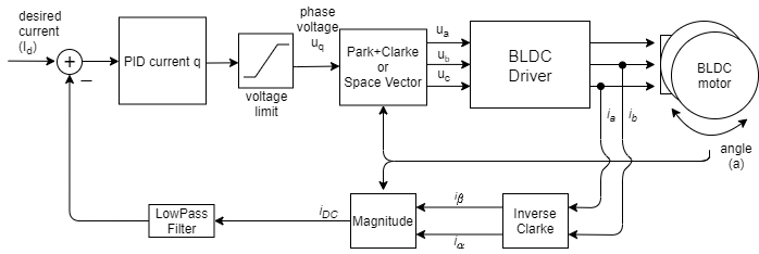
The DC Current Torque Control algorithm reads the phase current (usually ia and ib) of the BLDC motor. In addition, the algorithm reads the angle of the rotor from the position sensor. the Inverse Clarke and Park(simplified) is used.The transformation converts the phase current to a DC current iDC. The PID controller calculates the appropriate voltage value U q using the target current value I D and the measured I DC, and sets the motor U d to 0. Finally, the FOC algorithm sets the appropriate motor voltage U a, ub and u c. The FOC algorithm ensures that these voltages generate 90 degrees of magnetic force offset from the permanent magnet field in the motor rotor, thereby guaranteeing the maximum.Torque, which is called commutation.
The assumption of this torque control mode is that the torque generated in the motor is proportional to the DC current I DC that the motor absorbs (i DC = I q). Therefore, by controlling this current, our users can control the value of the torque. This assumption applies only to low speeds, where the I d component of the current becomes higher for higher speeds, and I DC = I Q no longer holds true.
configuration parameter
In order for the loop to run smoothly, the user needs to configure the PID controller parameter tehPID_current_q and the LPF_current_q time constant of the low-pass filter.
// PID parameters - default
motor.PID_current_q.P = 5;                       // 3    - Arduino UNO/MEGA
motor.PID_current_q.I = 1000;                    // 300  - Arduino UNO/MEGA
motor.PID_current_q.D = 0;
motor.PID_current_q.limit = motor.voltage_limit;
motor.PID_current_q.ramp = 1e6;                  // 1000 - Arduino UNO/MEGA
// Low pass filtering - default
LPF_current_q.Tf= 0.005;                         // 0.01 - Arduino UNO/MEGA
Torque Control Sample Code
A simple example of DC current based torque control using a series current sensor and setting the target value through a serial command interface.
#include <SimpleFOC.h>
// BLDC motor & driver instance
BLDCMotor motor = BLDCMotor(11);
BLDCDriver3PWM driver = BLDCDriver3PWM(9, 5, 6, 8);
// encoder instance
Encoder encoder = Encoder(2, 3, 500);
// channel A and B callbacks
void doA(){encoder.handleA();}
void doB(){encoder.handleB();}
// current sensor
InlineCurrentSense current_sense = InlineCurrentSense(0.01, 50.0, A0, A2);
// instantiate the commander
Commander command = Commander(Serial);
void doTarget(char* cmd) { command.variable(&motor.target, cmd); }
void setup() {
// initialize encoder sensor hardware
encoder.init();
encoder.enableInterrupts(doA, doB);
// link the motor to the sensor
motor.linkSensor(&encoder);
// driver config
// power supply voltage [V]
driver.voltage_power_supply = 12;
driver.init();
// link driver
motor.linkDriver(&driver);
// current sense init hardware
current_sense.init();
// link the current sense to the motor
motor.linkCurrentSense(¤t_sense);
// set torque mode:
motor.torque_controller = TorqueControlType::dc_current;
// set motion control loop to be used
motor.controller = MotionControlType::torque;
// foc current control parameters (Arduino UNO/Mega)
motor.PID_current_q.P = 5;
motor.PID_current_q.I= 300;
motor.LPF_current_q.Tf = 0.01;
// use monitoring with serial
Serial.begin(115200);
// comment out if not needed
motor.useMonitoring(Serial);
// initialize motor
motor.init();
// align sensor and start FOC
motor.initFOC();
// add target command T
command.add('T', doTarget, "target current");
Serial.println(F("Motor ready."));
Serial.println(F("Set the target current using serial terminal:"));
_delay(1000);
}
void loop() {
// main FOC algorithm function
motor.loopFOC();
// Motion control function
motor.move();
// user communication
command.run();
}==================================================================================================================================================
3.FOC Current Mode - foc_current
FOC current control is the only true torque control method. It controls the two components q and d of the flow direction. It is assumed that the torque is proportional to the q current component and the control current component d remains equal to 0.
compare
| Torque control type | Advantage | shortcoming |
|---|---|---|
| Voltage | ✔️ Very simple and fast ✔️ Any MCU All have good performance✔️ Very smooth at low speeds ✔️ No current induction required | ❌ Not optimal at high speed ❌ Unable to control real current consumption ❌ Torque is approximate (small error at low speed) |
| DC Current | ✔️ Real current consumption can be controlled ✔️ Suitable for low performance MUC ✔️ Current Limiting | ❌ More complex (slower) to execute ❌ Can achieve lower speed than voltage mode ❌ Torque approximation (small error at low speed) ❌ Current Induction Required |
| FOC Current | ✔️ True Torque Control (any speed) ✔️ Real current consumption can be controlled ✔️ Very effective at higher speeds ✔️ Current Limit | ❌ The most complex (slowest) execution ❌ Not suitable for low performance MCU s (may become unstable) ❌ Current Detection Required |
Torque control using FOC current
This torque control mode allows you to control the true torque of the BLDC motor, which requires current induction. Users set the target current I d to the FOC algorithm library, calculate the necessary phase voltage U a, u b and u c, and maintain operation by measuring the phase current (i a, I B and I c) and the rotor angle A. This mode is enabled by:
// FOC current torque control mode
motor.torque_controller = TorqueControlType::foc_current;
How it works
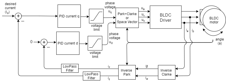
FOC Current Torque Control algorithm reads the phase current of BLDC motor (usually I a and I b)In addition, the algorithm reads the rotor angle alpha from the position sensor. The phase current is converted to D current I d and Q current I Q using the Inverse Clarke and Park transformation. Using the target current value I d and the measured current I Q and I d, the PID controller for each axis calculates the appropriate voltage U Q and U D settings to the motor, keeping I q = I D and I d = 0. Finally, Park+Clarke is used.(or SpaceVector) transformation, the FOC algorithm sets the appropriate u a, u b, and u c voltages for the motor. By measuring the phase current, this torque control algorithm ensures that these voltages generate the appropriate current and magnetic force in the motor's rotor and are offset exactly 90 degrees from its permanent magnet field, thereby guaranteeing the maximum torque, which is called commutation.
The torque generated in the motor is proportional to the q-axis current i q, making this torque control mode a true torque control for BLDC motors.
configuration parameter
In order for the loop to run smoothly, the user needs to configure the PID controller parameter tehPID_current_q and the LPF_current_q time constant of the low-pass filter.
// Q axis
// PID parameters - default
motor.PID_current_q.P = 5;                       // 3    - Arduino UNO/MEGA
motor.PID_current_q.I = 1000;                    // 300  - Arduino UNO/MEGA
motor.PID_current_q.D = 0;
motor.PID_current_q.limit = motor.voltage_limit;
motor.PID_current_q.ramp = 1e6;                  // 1000 - Arduino UNO/MEGA
// Low pass filtering - default
LPF_current_q.Tf= 0.005;                         // 0.01 - Arduino UNO/MEGA

// D axis
// PID parameters - default
motor.PID_current_d.P = 5;                       // 3    - Arduino UNO/MEGA
motor.PID_current_d.I = 1000;                    // 300  - Arduino UNO/MEGA
motor.PID_current_d.D = 0;
motor.PID_current_d.limit = motor.voltage_limit;
motor.PID_current_d.ramp = 1e6;                  // 1000 - Arduino UNO/MEGA
// Low pass filtering - default
LPF_current_d.Tf= 0.005;                         // 0.01 - Arduino UNO/MEGA
Torque Control Sample Code
A simple example of FOC-based current-based torque control using a series current sensor and setting the target value through a serial command interface.
#include <SimpleFOC.h>
// BLDC motor & driver instance
BLDCMotor motor = BLDCMotor(6);
BLDCDriver3PWM driver = BLDCDriver3PWM(9, 5, 6, 8);
// encoder instance
Encoder encoder = Encoder(2, 3, 4096);
// channel A and B callbacks
void doA(){encoder.handleA();}
void doB(){encoder.handleB();}
// current sensor
InlineCurrentSense current_sense = InlineCurrentSense(0.01, 50.0, A0, A2);
// instantiate the commander
Commander command = Commander(Serial);
void doTarget(char* cmd) { command.variable(&motor.target, cmd); }
void setup() {
// initialize encoder sensor hardware
encoder.init();
encoder.enableInterrupts(doA, doB);
// link the motor to the sensor
motor.linkSensor(&encoder);
// driver config
// power supply voltage [V]
driver.voltage_power_supply = 12;
driver.init();
// link driver
motor.linkDriver(&driver);
// current sense init hardware
current_sense.init();
// link the current sense to the motor
motor.linkCurrentSense(¤t_sense);
// set torque mode:
motor.torque_controller = TorqueControlType::foc_current;
// set motion control loop to be used
motor.controller = MotionControlType::torque;
// foc current control parameters (Arduino UNO/Mega)
motor.PID_current_q.P = 5;
motor.PID_current_q.I= 300;
motor.PID_current_d.P= 5;
motor.PID_current_d.I = 300;
motor.LPF_current_q.Tf = 0.01;
motor.LPF_current_d.Tf = 0.01;
// use monitoring with serial
Serial.begin(115200);
// comment out if not needed
motor.useMonitoring(Serial);
// initialize motor
motor.init();
// align sensor and start FOC
motor.initFOC();
// add target command T
command.add('T', doTarget, "target current");
Serial.println(F("Motor ready."));
Serial.println(F("Set the target current using serial terminal:"));
_delay(1000);
}
void loop() {
// main FOC algorithm function
motor.loopFOC();
// Motion control function
motor.move();
// user communication
command.run();
}==================================================================================================================================================
Motion Control Mode
A simple FOC library implements motion control in two situations:
- Closed-loop motion control -with position sensor
- Open-loop motion control - No location sensor
Closed-loop motion control
Three types of closed-loop motion control are implemented in Simple FOC library:
- Torque - MotionControlType::torque
- Speed - MotionControlType::velocity
- Angle - MotionControlType::angle
They can be set by changing the motor controller parameters.
// set motion control loop to be used
// MotionControlType::torque
// MotionControlType::velocity
// MotionControlType::angle
motor.controller = MotionControlType::angle;
More in-depth explanation of different closed-loop motion control loops
Motion Control
The simple FOC library allows you to choose to use three different closed-loop motion control strategies:
You can set it by changing the motor.controller variable. If you want to control the motor angle, you will set the controller to MotionControlType::angle, if you use voltage or current to find the torque MotionControlType::torque of the BLDC motor, if you want to control the motor angular speed MotionControlType::velocity.
// set FOC loop to be used
// MotionControlType::torque
// MotionControlType::velocity
// MotionControlType::angle
motor.controller = MotionControlType::angle;
Torque Control Loop
The simple FOC library gives you the option to use three different torque control strategies:
- Voltage mode-voltage
- DC Current Mode-dc_current
- FOC Current Mode-foc_current
In short, the voltage control mode is the simplest approximation of motor torque control. It is very basic and can operate on any combination of motor+driver+single-chip computer. DC current mode is the next step in motor torque approximation, which is much more accurate than voltage mode, but requires current induction and a stronger microcontroller.Current mode is the true torque that controls the motor. It is not an approximation. It also requires a current sensor and even more processing power than DC mode. See Torque Mode Document In-depth explanation.
Enable this motion control mode and set the controller parameter to:
// torque control loop
motor.controller = MotionControlType::torque;
If the voltage control mode is used and the user does not provide the phase resistance parameter to the motor, the input to the torque control circuit will be the target voltage U q:
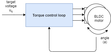
If one of the current-based Torque Control modes (DC current or FOC current) is used, the input to the control circuit will be the target current i q. This is also true in Voltage mode if the user supplies phase resistance values to the motor class.
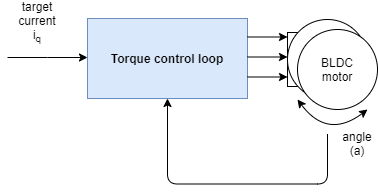
The Torque Control Loop serves as the basis for all other Motion Control Loops. For more information on the contents of the blue box, see Torque Mode Document.
configuration parameter
Depending on the type of torque control you want to use, you need to consider different parameters.
- Voltage mode - The simplest one - there is no parameter motor.phase_resistance other than possible
- DC Current Mode - 1xPID controller + 1xLPF
- FOC Current Mode - 2xPID controller + 2xLPF filter
Now, let's take an example!
Voltage control example
You can test the algorithm voltage_control.ino by running an example.
Here, we provide an example of a torque using a voltage control program and a full motion control configuration. The program uses the FOC algorithm to set a target U q voltage of 2V for the motor. Since the phase resistance parameter is not available, the motor target will be in volts.
#include <SimpleFOC.h>

// BLDC motor & driver instance
BLDCMotor motor = BLDCMotor(11);
BLDCDriver3PWM driver = BLDCDriver3PWM(9, 5, 6, 8);

// encoder instance
Encoder encoder = Encoder(2, 3, 500);
// channel A and B callbacks
void doA(){encoder.handleA();}
void doB(){encoder.handleB();}

void setup() {

  // initialize encoder sensor hardware
  encoder.init();
  encoder.enableInterrupts(doA, doB);
  // link the motor to the sensor
  motor.linkSensor(&encoder);

  // driver config
  // power supply voltage [V]
  driver.voltage_power_supply = 12;
  driver.init();
  // link driver
  motor.linkDriver(&driver);

  // set the torque control type
  motor.torque_controller = TorqueControlType::voltage;
  // set motion control loop to be used
  motor.controller = MotionControlType::torque;

  // use monitoring with serial
  Serial.begin(115200);
  // comment out if not needed
  motor.useMonitoring(Serial);

  // initialize motor
  motor.init();
  // align sensor and start FOC
  motor.initFOC();

  Serial.println(F("Motor ready."));
  Serial.println(F("Target voltage is 2V"));
  _delay(1000);
}

void loop() {

  // main FOC algorithm function
  motor.loopFOC();

  // Motion control function
  motor.move(2);
}
If we add a pahse resistance to the constructor of the BLDCMotor class, the motor target will be in amperes.
#include <SimpleFOC.h>

// BLDC motor & driver instance
BLDCMotor motor = BLDCMotor(11, 12.34); // 12.34 Ohms
BLDCDriver3PWM driver = BLDCDriver3PWM(9, 5, 6, 8);

// encoder instance
Encoder encoder = Encoder(2, 3, 500);
// channel A and B callbacks
void doA(){encoder.handleA();}
void doB(){encoder.handleB();}

void setup() {

  // initialize encoder sensor hardware
  encoder.init();
  encoder.enableInterrupts(doA, doB);
  // link the motor to the sensor
  motor.linkSensor(&encoder);

  // driver config
  // power supply voltage [V]
  driver.voltage_power_supply = 12;
  driver.init();
  // link driver
  motor.linkDriver(&driver);

  // set the torque control type
  motor.torque_controller = TorqueControlType::voltage;
  // set motion control loop to be used
  motor.controller = MotionControlType::torque;

  // use monitoring with serial
  Serial.begin(115200);
  // comment out if not needed
  motor.useMonitoring(Serial);

  // initialize motor
  motor.init();
  // align sensor and start FOC
  motor.initFOC();

  Serial.println(F("Motor ready."));
  Serial.println(F("Target current is 0.5Amps"));
  _delay(1000);
}

void loop() {

  // main FOC algorithm function
  motor.loopFOC();

  // Motion control function
  motor.move(0.5);
}
===========================================================================
Speed control circuit
The control loop allows you to rotate the motor at the desired speed. This mode is enabled by:
// set velocity motion control loop
motor.controller = MotionControlType::velocity;
You can test this algorithm by running an example in the motion_control/velocity_motion_control/folder.
How does this work
Speed control closes the control circuit around the torque control, regardless of which one it is. If there is no voltage mode with phase resistance set, speed movement control will use voltage U q::

If either the current torque control mode (FOC or DC current) or the voltage mode that provides phase resistance, the speed motion control will set the target current i q:
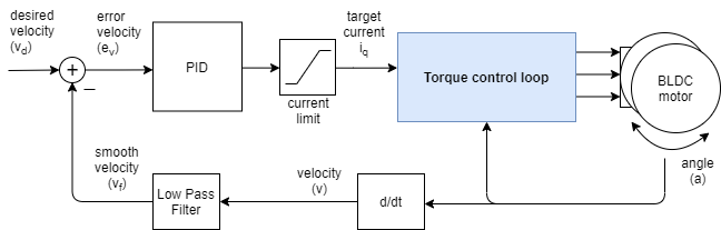
Speed control is achieved by using the In Torque Control Loop A PID speed controller is added to achieve this. The PID controller reads the motor speed v, filters it to V f and sets the target of the torque (u q voltage or i q current) to the torque control circuit so that it reaches and maintains the target speed V d set by the user.
Controller parameters
To adjust this control loop, you can set the parameters to an angle PID controller and a speed measurement low-pass filter.
// controller configuration based on the control type
// velocity PID controller parameters
// default P=0.5 I = 10 D = 0
motor.PID_velocity.P = 0.2;
motor.PID_velocity.I = 20;
motor.PID_velocity.D = 0.001;
// jerk control using voltage voltage ramp
// default value is 300 volts per sec  ~ 0.3V per millisecond
motor.PID_velocity.output_ramp = 1000;

// velocity low pass filtering
// default 5ms - try different values to see what is the best.
// the lower the less filtered
motor.LPF_velocity.Tf = 0.01;

// setting the limits
// either voltage
motor.voltage_limit = 10; // Volts - default driver.voltage_limit
// of current
motor.current_limit = 2; // Amps - default 0.2Amps
The parameters of the PID controller are proportional gain P, integral gain I, differential gain D, and output_ramp.
- Generally speaking, by increasing the proportional gain P, your motor controller will be more responsive, but too much will make it unstable. Setting it to 0 will disable the proportional part of the controller.
- The same is true for integral gain I. The higher it is, the faster the motor will respond to disturbances, but too large a value will make it unstable. Setting it to 0 disables the components of the controller.
- The derivative part D of the controller is usually the hardest to set, so it is recommended to set it to 0, first adjust P and I. Once they are adjusted, if you have a overshoot, you can add some D components to cancel it.
- The output_ramp value is designed to reduce the maximum change in the voltage value sent to the motor. The higher the PI controller value, the faster the U q value changes. The smaller the value, the smaller the possible change and the slower the controller responds. The value of this parameter is set to Volts per second[V/s or, in other words, how many volts can your controller raise the voltage in a single unit of time. If you set the voltage_ramp value to 10 V/s, on average, your control cycle will run every 1ms. Your controller will be able to change the U q value 10[V/s]*0.001[s] = 0.01V each time, rather than a lot.
In addition, in order to smooth the speed measurement, the Simple FOC library implements a speed low-pass filter. low pass filter It is the standard form of signal smoothing and has only one parameter, the filter time constant Tf.
- The lower the value, the smaller the impact of the filter. If you remove Tf from 0 you essentially delete the filter entirely. It's difficult to guess the exact value of the Tf implementation in advance, but Tf usually forms a range of 0 to 0.5 seconds somewhere.
voltage_limit applies if for some reason you want to limit the voltage that can be sent to the motor.
For optimal performance, you will have to make some adjustments to the parameters.😁
Example of speed motion control
This is a basic example of speed motion control with fully configured voltage mode torque control. The program will set the target speed of 2 RAD/s and keep it (resistant to interference).
#include <SimpleFOC.h>

// motor instance
BLDCMotor motor = BLDCMotor( pole_pairs , phase_resistance );
// driver instance
BLDCDriver3PWM driver = BLDCDriver3PWM(pwmA, pwmB, pwmC, enable);

// Magnetic sensor instance
MagneticSensorSPI AS5x4x = MagneticSensorSPI(chip_select, 14, 0x3FFF);

void setup() {

  // initialize magnetic sensor hardware
  AS5x4x.init();
  // link the motor to the sensor
  motor.linkSensor(&AS5x4x);

  // driver config
  driver.init();
  motor.linkDriver(&driver);

  // set motion control loop to be used
  motor.controller = MotionControlType::velocity;

  // controller configuration
  // default parameters in defaults.h

  // controller configuration based on the control type
  // velocity PID controller parameters
  // default P=0.5 I = 10 D =0
  motor.PID_velocity.P = 0.2;
  motor.PID_velocity.I = 20;
  motor.PID_velocity.D = 0.001;
  // jerk control using voltage voltage ramp
  // default value is 300 volts per sec  ~ 0.3V per millisecond
  motor.PID_velocity.output_ramp = 1000;

  // velocity low pass filtering
  // default 5ms - try different values to see what is the best.
  // the lower the less filtered
  motor.LPF_velocity.Tf = 0.01;

  // since the phase resistance is provided we set the current limit not voltage
  // default 0.2
  motor.current_limit = 1; // Amps

  // use monitoring with serial
  Serial.begin(115200);
  // comment out if not needed
  motor.useMonitoring(Serial);

  // initialize motor
  motor.init();
  // align sensor and start FOC
  motor.initFOC();

  Serial.println("Motor ready.");
  _delay(1000);
}

// velocity set point variable
float target_velocity = 2; // 2Rad/s ~ 20rpm

void loop() {
  // main FOC algorithm function
  motor.loopFOC();

  // Motion control function
  motor.move(target_velocity);
}
==================================================================================================================================================
Position control circuit
The control loop allows you to move the motor to the desired angle in real time. This mode is enabled by:
// set angle/position motion control loop
motor.controller = MotionControlType::angle;
You can test this algorithm by running an example in the motion_control/position_motion_control/folder.
How does this work
Angle/position control closes the control loop around the speed control loop. Speed control closes the control loop around the torque control, regardless of which one it is. If there is no voltage mode with phase resistance set, speed motion control uses voltage U q::
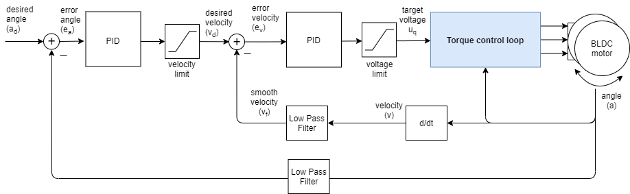
In the case of any current torque control mode (FOC or DC current) or voltage mode that provides phase resistance, angular motion control sets the target current i q to the torque controller:
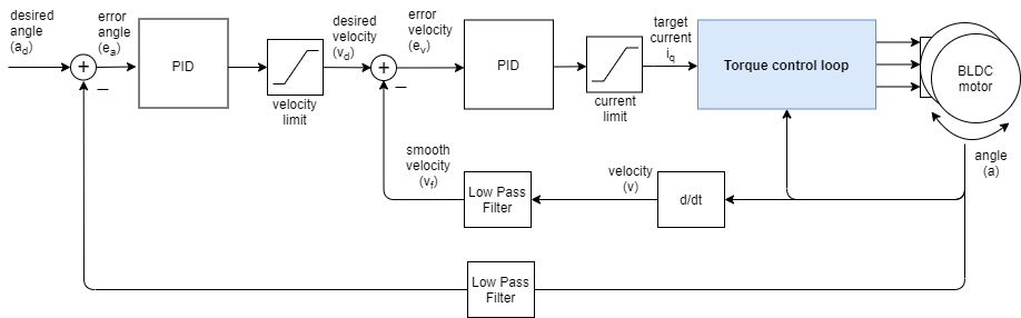
So by Speed control back A cascade control loop is added to the road to create an angle control loop, as shown in the figure above. The loop is closed by using an additional PID controller and an optional low-pass filter. The controller reads the angle a from the motor (the filter is optional)Then the speed controller reads the current filter speed from the motor V f and sets the torque target (u q voltage or i q current) to the torque control circuit, which needs to reach the speed v d, which is set by the angle circuit.
Controller parameters
To adjust this control loop, you can set the parameters to the first speed PID controller, low-pass filter, and limit.
// velocity PID controller parameters
// default P=0.5 I = 10 D =0
motor.PID_velocity.P = 0.2;
motor.PID_velocity.I = 20;
motor.PID_velocity.D = 0.001;
// jerk control using voltage voltage ramp
// default value is 300 volts per sec  ~ 0.3V per millisecond
motor.PID_velocity.output_ramp = 1000;

// velocity low pass filtering
// default 5ms - try different values to see what is the best.
// the lower the less filtered
motor.LPF_velocity.Tf = 0.01;

// setting the limits
// either voltage
motor.voltage_limit = 10; // Volts - default driver.voltage_limit
// of current
motor.current_limit = 2; // Amps - default 0.2Amps
Then the angle PID controller, low-pass filter, and restriction:
// angle PID controller
// default P=20
motor.P_angle.P = 20;
motor.P_angle.I = 0;  // usually only P controller is enough
motor.P_angle.D = 0;  // usually only P controller is enough
// acceleration control using output ramp
// this variable is in rad/s^2 and sets the limit of acceleration
motor.P_angle.output_ramp = 10000; // default 1e6 rad/s^2

// angle low pass filtering
// default 0 - disabled
// use only for very noisy position sensors - try to avoid and keep the values very small
motor.LPF_angle.Tf = 0; // default 0

// setting the limits
//  maximal velocity of the position control
motor.velocity_limit = 4; // rad/s - default 20
It is important to parameterize speed and angle PID controllers for optimal performance. Speed PID controllers are updated by In speed control circuit The motor.PID_velocity structure described is parameterized.
- The rough rule should be to reduce the proportional gain P to achieve less vibration.
- You may not have to touch the I or D values.
Angle PID controllers can be updated by changing the motor.P_angle structure.
- In most applications, a simple P controller is sufficient (I=D=0)
- Proportional gain P makes it more responsive, but too high a value makes it unstable and causes vibration.
- output_ramp value is equivalent to the acceleration limit - the default value is close to infinity and can be lowered if needed.
For angle control, you can also see the effect of the speed LPF filter.
- LPF_velocity.Tf should not change much from speed control to angle control, so once you adjust the speed cycle, you can keep it as it is.
- LPF_angle.Tf will remain equal to 0 in most cases, which makes it disabled.
In addition, you can configure the value of the velocity_limit controller, which prevents the controller from setting too high a speed v d for the motor.
- If you turn your velocity_limit's motor very low, your motor will move between desired positions at this speed. If you keep it high, you will not even notice that this variable exists.😃
Finally, each application is slightly different, and you may need to adjust the controller values slightly to achieve the desired behavior.
For more theory and source code documentation on this method, see A deeper section.
Location Control Sample Code
This is a very basic example of a position motion control program based on a fully configured voltage-torque control. When this code is run, the motor will move 1 sec between each angle of -1 RAD and 1 RAD.
#include <SimpleFOC.h>

// motor instance
BLDCMotor motor = BLDCMotor(11);
// driver instance
BLDCDriver3PWM driver = BLDCDriver3PWM(9, 10, 11, 8);

// encoder instance
Encoder encoder = Encoder(2, 3, 500);
// channel A and B callbacks
void doA(){encoder.handleA();}
void doB(){encoder.handleB();}

void setup() {

  // initialize encoder sensor hardware
  encoder.init();
  encoder.enableInterrupts(doA, doB);
  // link the motor to the sensor
  motor.linkSensor(&encoder);

  // driver config
  driver.init();
  motor.linkDriver(&driver);

  // set motion control loop to be used
  motor.controller = MotionControlType::angle;

  // controller configuration
  // default parameters in defaults.h

  // controller configuration based on the control type
  // velocity PID controller parameters
  // default P=0.5 I = 10 D =0
  motor.PID_velocity.P = 0.2;
  motor.PID_velocity.I = 20;
  motor.PID_velocity.D = 0.001;
  // jerk control using voltage voltage ramp
  // default value is 300 volts per sec  ~ 0.3V per millisecond
  motor.PID_velocity.output_ramp = 1000;

  // velocity low pass filtering
  // default 5ms - try different values to see what is the best.
  // the lower the less filtered
  motor.LPF_velocity.Tf = 0.01;

  // angle P controller -  default P=20
  motor.P_angle.P = 20;

  //  maximal velocity of the position control
  // default 20
  motor.velocity_limit = 4;
  // default voltage_power_supply
  motor.voltage_limit = 10;

  // use monitoring with serial
  Serial.begin(115200);
  // comment out if not needed
  motor.useMonitoring(Serial);

  // initialize motor
  motor.init();
  // align encoder and start FOC
  motor.initFOC();


  Serial.println("Motor ready.");
  _delay(1000);
}

// angle set point variable
float target_angle = 1;
// timestamp for changing direction
long timestamp_us = _micros();

void loop() {

  // each one second
  if(_micros() - timestamp_us > 1e6) {
      timestamp_us = _micros();
      // inverse angle
      target_angle = -target_angle;
  }

  // main FOC algorithm function
  motor.loopFOC();

  // Motion control function
  motor.move(target_angle);
}
==================================================================================================================================
Open-loop motion control
In addition, you can operate the motor in an open-loop mode without feedback from the position sensor:
- Speed Open-loop Control - MotionControlType::velocity_openloop
- Location Open-loop Control - MotionControlType::angle_openloop
They can also be enabled by setting the motor controller parameters.
// MotionControlType::velocity_openloop    - velocity open-loop control
// MotionControlType::angle_openloop       - position open-loop control
motor.controller = MotionControlType::angle_openloop;
For a more in-depth explanation of the different closed-loop motion control loops, please visit Open-loop Control Document
Motion Control
A simple FOC library allows you to choose between two different open-loop control strategies:
Open-loop location control is also used for index search usage, but with some additional parameters, see Index Search
// MotionControlType::velocity_openloop    - velocity open-loop control
// MotionControlType::angle_openloop       - position open-loop control
motor.controller = MotionControlType::angle_openloop;
Speed Open-loop Control
The control loop allows you to rotate the BLDC motor at the desired speed without using a position sensor. This mode is enabled by:
// set velocity control open-loop mode
motor.controller = MotionControlType::velocity_openloop;
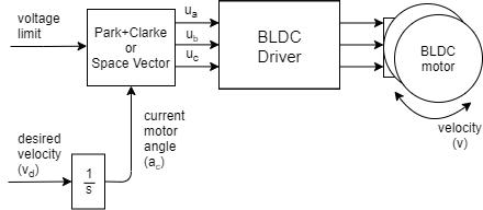
You can test this algorithm by running an example in the motion_control/openloop_motor_control/folder.
This control algorithm is very simple. The user can set the target speed v d it wants to reach, and the algorithm will integrate it in time to find out what angle it needs to set to motor a c to achieve it. Then motor.voltage_limit will be applied the maximum allowable voltage in the direction that a c uses SinePWM or SpaceVector PWM modulation.
This is a simplified version of calculating the next angle to be set to the motor:
next_angle = past_angle + target_velocity*d_time;
You need to know the target_velocity of the angle set for the motor, the sampling time d_time, and the past_angle.
To configure
// choose FOC modulation (optional) - default SinePWM
motor.foc_modulation = FOCModulationType::SpaceVectorPWM;

// limiting voltage
motor.voltage_limit = 3;   // Volts
// or current  - if phase resistance provided
motor.current_limit = 0.5 // Amps
This type of motion control is very inefficient, so try not to use the high value motor.voltage_limit. We recommend that you provide a phase_resistance value for the motor level and set the motor.current_limit voltage limit. This current may be exceeded, but at least you will know the approximate current your motor is consuming. You can do this by checking the motor resistance phase_resistance and evaluating it.To calculate the current that the motor will generate:
voltage_limit = current_limit * phase_resistance; // Amps
In addition, if your application requires this behavior, you can change the voltage/current limit in real time.
Open-loop speed control example
Below is a basic example of a fully configured speed open-loop control. The program sets and maintains the target speed of 2 RAD/s, which users can change through a serial terminal.
// Open loop motor control example
#include <SimpleFOC.h>

// BLDC motor & driver instance
// BLDCMotor( pp number , phase resistance)
BLDCMotor motor = BLDCMotor(11 , 12.5);
BLDCDriver3PWM driver = BLDCDriver3PWM(9, 5, 6, 8);

//target variable
float target_velocity = 2; // rad/s

// instantiate the commander
Commander command = Commander(Serial);
void doTarget(char* cmd) { command.variable(&target_velocity, cmd); }

void setup() {

  // driver config
  // power supply voltage [V]
  driver.voltage_power_supply = 12;
  driver.init();
  // link the motor and the driver
  motor.linkDriver(&driver);

  // limiting motor current (provided resistance)
  motor.current_limit = 0.5;   // [Amps]

  // open loop control config
  motor.controller = MotionControlType::velocity_openloop;

  // init motor hardware
  motor.init();

  // add target command T
  command.add('T', doTarget, "target velocity");

  Serial.begin(115200);
  Serial.println("Motor ready!");
  Serial.println("Set target velocity [rad/s]");
  _delay(1000);
}

void loop() {

  // open loop velocity movement
  // using motor.current_limit and motor.velocity_limit
  motor.move(target_velocity);

  // user communication
  command.run();
}
Location Open-loop Control
The control loop allows you to move the motor to the desired angle in real time without using a position sensor. This mode is enabled in the following ways:
// set position motion control open-loop
motor.controller = MotionControlType::angle_openloop;
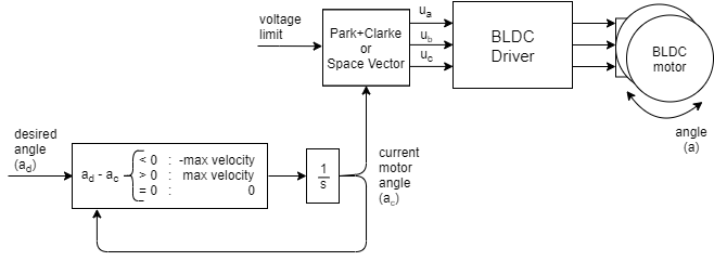
You can test this algorithm by running an example in the motion_control/open_loop_motor_control/folder.
This control algorithm is very simple. The user sets the angle that he wants to reach the target one day. The algorithm subtracts only the current angle a c and the required angle a d to find the direction in which it needs to move and moves in that direction at the highest possible speed motor.velocity_limit. To set this speed, it uses the Speed Open-loop Control Same algorithm. It integrates the speed in time to find out the angle a c it needs to set for the motor to implement it. Then SinePWMSpaceVector modulation with or motor.voltage_limit is applied in the direction a c.
To configure
// choose FOC modulation (optional)
motor.foc_modulation = FOCModulationType::SpaceVectorPWM;

//  maximal velocity of the position control
// default 20
motor.velocity_limit = 20;

// limiting voltage
motor.voltage_limit = 3;   // Volts
// or current  - if phase resistance provided
motor.current_limit = 0.5 // Amps
This type of motion control is very inefficient, so try not to use the high value motor.voltage_limit. We recommend that you provide a phase_resistance value for the motor level and set the motor.current_limit voltage limit. This current may be exceeded, but at least you will know the approximate current your motor is consuming. You can do this by checking the motor resistance phase_resistance and evaluating it.To calculate the current that the motor will generate:
voltage_limit = current_limit * phase_resistance; // Amps
The maximum speed motor.velocity_limit value determines the speed at which your motors operate between locations. The higher the value, the faster the conversion. However, since we turn the motor in an open loop, we will not know if it can follow the speed. Therefore, make sure that velocity_limit enters the value that your motor can achieve. Also note that to achieve higher speed and maintain greater torque,You also need to add the motor.voltage_limit or motor.current_limit variable.
In addition, if your application requires this behavior, you can change the voltage limit motor.voltage_limit (motor.current_limit) and the conversion speed motor.velocity_limit in real time.
Location open-loop control example
The following is a basic example of a fully configured speed open-loop control. The program sets a 0 RAD and maintains its target location, which users can change through a serial terminal.
// Open loop motor control example
#include <SimpleFOC.h>

// BLDC motor & driver instance
BLDCMotor motor = BLDCMotor(11);
BLDCDriver3PWM driver = BLDCDriver3PWM(9, 5, 6, 8);

//target variable
float target_position = 0;

// instantiate the commander
Commander command = Commander(Serial);
void doTarget(char* cmd) { command.variable(&target_position, cmd); }

void setup() {

  // driver config
  // power supply voltage [V]
  driver.voltage_power_supply = 12;
  driver.init();
  // link the motor and the driver
  motor.linkDriver(&driver);

  // limiting motor movements
  motor.voltage_limit = 3;   // [V]
  motor.velocity_limit = 5; // [rad/s] cca 50rpm
  // open loop control config
  motor.controller = MotionControlType::angle_openloop;

  // init motor hardware
  motor.init();

  // add target command T
  command.add('T', doTarget, "target angle");

  Serial.begin(115200);
  Serial.println("Motor ready!");
  Serial.println("Set target position [rad]");
  _delay(1000);
}

void loop() {
  // open  loop angle movements
  // using motor.voltage_limit and motor.velocity_limit
  motor.move(target_position);

  // user communication
  command.run();
}
Index Search Routine
Find encoder index is performed only if the constructor of the Encoder class has provided an indexpin. Search is performed by setting the constant speed of the motor until it reaches the pin. To set the required search speed, change the parameters:
// index search velocity - default 1rad/s
motor.velocity_index_search = 2;
Index searches are performed in the motor.initFOC() function.
Realization and implementation of the speed control loop Speed Opening The only difference is that the voltage set to the motor is not motor.volatge_limit (or motor.curren_limit*motor.phase_resistance) but motor.voltage_sensor_align.
Code sample using index search
This is an example of a motion control program that uses an encoder as a position sensor, especially an encoder with an index signal. The index search speed is set to 3 RAD/s:
// index search velocity [rad/s]
motor.velocity_index_search = 3;
motor.initFOC() aligns the motor with the position sensor through an index search. The motor will start rotating 2 RAD/s at an angular speed and maintain this value.
#include <SimpleFOC.h>

// motor instance
BLDCMotor motor = BLDCMotor(11);
// driver instance
BLDCDriver3PWM driver = BLDCDriver3PWM(9, 10, 11, 8);

// encoder instance
Encoder encoder = Encoder(2, 3, 500, A0);
// channel A and B callbacks
void doA(){encoder.handleA();}
void doB(){encoder.handleB();}
void doIndex(){encoder.handleIndex();}


void setup() {

  // initialize encoder sensor hardware
  encoder.init();
  encoder.enableInterrupts(doA, doB,doIndex);

  // link the motor to the sensor
  motor.linkSensor(&encoder);

  // driver config
  driver.init();
  motor.linkDriver(&driver);

  // index search velocity [rad/s]
  motor.velocity_index_search = 3; // rad/s
  motor.voltage_sensor_align = 4; // Volts

  // set motion control loop to be used
  motor.controller = MotionControlType::velocity;

  // controller configuration
  // default parameters in defaults.h

  // velocity PI controller parameters
  motor.PID_velocity.P = 0.2;
  motor.PID_velocity.I = 20;
  // default voltage_power_supply
  motor.voltage_limit = 6;
  // jerk control using voltage voltage ramp
  // default value is 300 volts per sec  ~ 0.3V per millisecond
  motor.PID_velocity.output_ramp = 1000;

  // velocity low pass filtering time constant
  motor.LPF_velocity.Tf = 0.01;


  // use monitoring with serial
  Serial.begin(115200);
  // comment out if not needed
  motor.useMonitoring(Serial);

  // initialize motor
  motor.init();
  // align encoder and start FOC
  motor.initFOC();


  Serial.println("Motor ready.");
  _delay(1000);
}

// angle set point variable
float target_velocity = 2;

void loop() {
  // main FOC algorithm function
  motor.loopFOC();

  // Motion control function
  motor.move(target_velocity);

}
Software translation is not appropriate, so I will change it later.