This article is compiled and published by jiumo (Ma Zhi), chief lecturer of HeapDump performance community
Chapter 17 - x86-64 register
The system of machine language that can be interpreted by different CPUs is called ISA (Instruction Set Architecture), or instruction set. Intel calls the 32-bit CPU Instruction Set Architecture among x86 series CPUs IA-32. IA is the abbreviation of "Intel Architecture", which can also be called i386 and x86-32. Amd equals Intel and proposes the 64 bit extension of X86 series, so the 64 bit Instruction Set Architecture of X86 series designed by AMD is called AMD64. Later, Intel added almost the same instruction set as AMD64 to its CPU, which is called Intel 64 instruction set. AMD64 and Intel 64 can be collectively referred to as x86-64.
All registers of x86-64 are the same as the machine word length (data bus bit width), that is, 64 bits. X86-64 expands the eight 32-bit general registers of X86 to 64 bits (eax, ebx, ecx, edx, eci, edi, ebp, esp), and adds eight new 64 bit registers (r8-r15). In terms of naming method, it also changes from "exx" to "rxx", but still retains "exx" for 32-bit operation, The following table describes the naming and function of each register.
| describe | 32 bit | 64 bit |
| General register group | eax | rax |
| ecx | rcx | |
| edx | rdx | |
| ebx | rbx | |
| esp | rsp | |
| ebp | rbp | |
| esi | rsi | |
| edi | rdi | |
| - | r8~r15 | |
| Floating point register group | st0~st7 | st0~st7 |
| XMM register group | XMM0~XMM7 | XMM0~XMM15 |
The% esp and% ebp have special purposes to hold pointers to specific locations in the program stack.
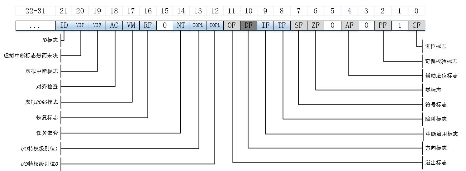
In addition, there is the eflags register, which represents the specific meaning through bits, as shown in the figure below.

In HotSpot VM, all classes representing registers inherit from AbstractRegisterImpl class. The definition of this class is as follows:
Source code location: hotspot/src/share/vm/asm/register.hpp

class AbstractRegisterImpl;
typedef AbstractRegisterImpl* AbstractRegister;

class AbstractRegisterImpl {
 protected:
  int value() const  { return (int)(intx)this; }
};
The inheritance system of AbstractRegisterImpl class is shown in the following figure.
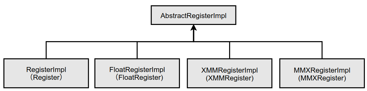
In addition, another concreteregisterinpl class also inherits abstractregisterinpl, which is related to the implementation of C2 compiler and will not be explained here.
1. RegisterImpl class
RegisterImpl class is used to represent general registers. The class is defined as follows:
Source code location: cpu/x86/vm/register_x86.hpp

// Use Register as the abbreviation of RegisterImpl
class RegisterImpl;
typedef RegisterImpl* Register;

class RegisterImpl: public AbstractRegisterImpl {
 public:
  enum {
    number_of_registers      = 16,
    number_of_byte_registers = 16
  };
  // ...
};
For 64 bits, the bit width of the general-purpose register is 64 bits. A part of eax, ebx, ecx and edx can also be used as an 8-bit register, so the number of registers that can store bytes is 4.
Define registers in HotSpot VM as follows:
Source code location: hotspot/src/cpu/x86/vm/register_x86.hpp

CONSTANT_REGISTER_DECLARATION(Register, noreg, (-1)); // noreg_RegisterEnumValue = ((-1))
CONSTANT_REGISTER_DECLARATION(Register, rax,    (0)); // rax_RegisterEnumValue = ((0))
CONSTANT_REGISTER_DECLARATION(Register, rcx,    (1)); // rcx_RegisterEnumValue = ((1))
CONSTANT_REGISTER_DECLARATION(Register, rdx,    (2)); // rdx_RegisterEnumValue = ((2))
CONSTANT_REGISTER_DECLARATION(Register, rbx,    (3)); // rbx_RegisterEnumValue = ((3))
CONSTANT_REGISTER_DECLARATION(Register, rsp,    (4)); // rsp_RegisterEnumValue = ((4))
CONSTANT_REGISTER_DECLARATION(Register, rbp,    (5)); // rbp_RegisterEnumValue = ((5))
CONSTANT_REGISTER_DECLARATION(Register, rsi,    (6)); // rsi_RegisterEnumValue = ((6))
CONSTANT_REGISTER_DECLARATION(Register, rdi,    (7)); // rdi_RegisterEnumValue = ((7))
CONSTANT_REGISTER_DECLARATION(Register, r8,     (8)); // r8_RegisterEnumValue = ((8))
CONSTANT_REGISTER_DECLARATION(Register, r9,     (9)); // r9_RegisterEnumValue = ((9))
CONSTANT_REGISTER_DECLARATION(Register, r10,   (10)); // r10_RegisterEnumValue = ((10))
CONSTANT_REGISTER_DECLARATION(Register, r11,   (11)); // r11_RegisterEnumValue = ((11))
CONSTANT_REGISTER_DECLARATION(Register, r12,   (12)); // r12_RegisterEnumValue = ((12))
CONSTANT_REGISTER_DECLARATION(Register, r13,   (13)); // r13_RegisterEnumValue = ((13))
CONSTANT_REGISTER_DECLARATION(Register, r14,   (14)); // r14_RegisterEnumValue = ((14))
CONSTANT_REGISTER_DECLARATION(Register, r15,   (15)); // r15_RegisterEnumValue = ((15))
Macro constant_ REGISTER_ Definition is defined as follows:
Source code location: hotspot/src/share/vm/asm/register.hpp

#define CONSTANT_REGISTER_DECLARATION(type, name, value)   \
  extern const type name;                                  \
  enum { name##_##type##EnumValue = (value) }
After macro expansion, it is as follows:
extern const Register  rax;
enum { rax_RegisterEnumValue = ((0)) }
extern const Register  rcx;
enum { rcx_RegisterEnumValue = ((1)) }
extern const Register  rdx;
enum { rdx_RegisterEnumValue = ((2)) }
extern const Register  rbx;
enum { rbx_RegisterEnumValue = ((3)) }
extern const Register  rsp;
enum { rsp_RegisterEnumValue = ((4)) }
extern const Register  rbp;
enum { rbp_RegisterEnumValue = ((5)) }
extern const Register  rsi;
enum { rsi_RegisterEnumValue = ((6)) }
extern const Register  rsi;
enum { rdi_RegisterEnumValue = ((7)) }
extern const Register  r8;
enum { r8_RegisterEnumValue = ((8)) }
extern const Register  r9;
enum { r9_RegisterEnumValue = ((9)) }
extern const Register  r10;
enum { r10_RegisterEnumValue = ((10)) }
extern const Register  r11;
enum { r11_RegisterEnumValue = ((11)) }
extern const Register  r12;
enum { r12_RegisterEnumValue = ((12)) }
extern const Register  r13;
enum { r13_RegisterEnumValue = ((13)) }
extern const Register  r14;
enum { r14_RegisterEnumValue = ((14)) }
extern const Register  r15;
enum { r15_RegisterEnumValue = ((15)) }
The enumeration class above assigns a constant value to the register.
On CPU / x86 / VM / register_ definitions_ The registers defined in the x86.cpp file are as follows:
const Register  noreg = ((Register)noreg_RegisterEnumValue)
const Register  rax =   ((Register)rax_RegisterEnumValue)
const Register  rcx =   ((Register)rcx_RegisterEnumValue)
const Register  rdx =   ((Register)rdx_RegisterEnumValue)
const Register  rbx =   ((Register)rbx_RegisterEnumValue)
const Register  rsp =   ((Register)rsp_RegisterEnumValue)
const Register  rbp =   ((Register)rbp_RegisterEnumValue)
const Register  rsi =   ((Register)rsi_RegisterEnumValue)
const Register  rdi =   ((Register)rdi_RegisterEnumValue)
const Register  r8 =  ((Register)r8_RegisterEnumValue)
const Register  r9 =  ((Register)r9_RegisterEnumValue)
const Register  r10 = ((Register)r10_RegisterEnumValue)
const Register  r11 = ((Register)r11_RegisterEnumValue)
const Register  r12 = ((Register)r12_RegisterEnumValue)
const Register  r13 = ((Register)r13_RegisterEnumValue)
const Register  r14 = ((Register)r14_RegisterEnumValue)
const Register  r15 = ((Register)r15_RegisterEnumValue)
When we need to use general registers, we can refer to them through variables such as rax and rcx.
2,FloatRegisterImpl
In HotSpot VM, floatregisterinpl is used to represent floating-point registers. This class is defined as follows:
Source code location: hotspot/src/cpu/x86/vm/register_x86.hpp

// Use FloatRegister for short
class FloatRegisterImpl;
typedef FloatRegisterImpl* FloatRegister;

class FloatRegisterImpl: public AbstractRegisterImpl {
 public:
  enum {
    number_of_registers = 8
  };
  // ...
}
There are 8 floating-point registers, st0~st7, which are 8 80 bit registers.
It should be noted here that there is another register MMX. MMX is not a new register, but borrows the lower 64 bits of the 80 bit floating-point register. In other words, using the MMX instruction set will affect the floating-point operation!
3,MMXRegisterImpl
MMX is a SIMD technology, which can perform multiple data operations through one instruction. It has eight 64 bit registers (borrowing the lower 64 bits of the 80 bit floating-point register), respectively mm0 – mm7. The difference between MMX and other ordinary 64 bit registers is that it can calculate two 32-bit data or four 16 bit data at the same time through its instructions, It can be applied to the calculation of graphic color during image processing.
The MMXRegisterImpl class is defined as follows:
class MMXRegisterImpl;
typedef MMXRegisterImpl* MMXRegister;
The MMX register is defined as follows:
CONSTANT_REGISTER_DECLARATION(MMXRegister, mnoreg , (-1));
CONSTANT_REGISTER_DECLARATION(MMXRegister, mmx0 , ( 0));
CONSTANT_REGISTER_DECLARATION(MMXRegister, mmx1 , ( 1));
CONSTANT_REGISTER_DECLARATION(MMXRegister, mmx2 , ( 2));
CONSTANT_REGISTER_DECLARATION(MMXRegister, mmx3 , ( 3));
CONSTANT_REGISTER_DECLARATION(MMXRegister, mmx4 , ( 4));
CONSTANT_REGISTER_DECLARATION(MMXRegister, mmx5 , ( 5));
CONSTANT_REGISTER_DECLARATION(MMXRegister, mmx6 , ( 6));
CONSTANT_REGISTER_DECLARATION(MMXRegister, mmx7 , ( 7));
After macro expansion:
extern const MMXRegister  mnoreg;
enum { mnoreg_MMXRegisterEnumValue = ((-1)) }
extern const MMXRegister  mmx0;
enum { mmx0_MMXRegisterEnumValue = (( 0)) }
extern const MMXRegister  mmx1;
enum { mmx1_MMXRegisterEnumValue = (( 1)) }
extern const MMXRegister  mmx2;
enum { mmx2_MMXRegisterEnumValue = (( 2)) }
extern const MMXRegister  mmx3;
enum { mmx3_MMXRegisterEnumValue = (( 3)) }
extern const MMXRegister  mmx4;
enum { mmx4_MMXRegisterEnumValue = (( 4)) }
extern const MMXRegister  mmx5;
enum { mmx5_MMXRegisterEnumValue = (( 5)) }
extern const MMXRegister  mmx6;
enum { mmx6_MMXRegisterEnumValue = (( 6)) }
extern const MMXRegister  mmx7;
enum { mmx7_MMXRegisterEnumValue = (( 7)) }
There are 8 64 bit registers from mm0 to mm7 in the CPU after MMX Pentium and Pentium II. But in fact, MMX registers and floating-point registers are common, that is, floating-point registers and MMX registers cannot be used at the same time.
cpu/x86/vm/register_ definitions_ The register variables defined in the x86.cpp file are as follows:
const MMXRegister  mnoreg = ((MMXRegister)mnoreg_MMXRegisterEnumValue)
const MMXRegister  mmx0 =   ((MMXRegister)mmx0_MMXRegisterEnumValue)
const MMXRegister  mmx1 =   ((MMXRegister)mmx1_MMXRegisterEnumValue)
const MMXRegister  mmx2 =   ((MMXRegister)mmx2_MMXRegisterEnumValue)
const MMXRegister  mmx3 =   ((MMXRegister)mmx3_MMXRegisterEnumValue)
const MMXRegister  mmx4 =   ((MMXRegister)mmx4_MMXRegisterEnumValue)
const MMXRegister  mmx5 =   ((MMXRegister)mmx5_MMXRegisterEnumValue)
const MMXRegister  mmx6 =   ((MMXRegister)mmx6_MMXRegisterEnumValue)
const MMXRegister  mmx7 =   ((MMXRegister)mmx7_MMXRegisterEnumValue)
When we need to use MMX register, we can refer to it through variables such as mmx0 and mmx1.
4. XMMRegisterImpl class
XMM register is a register for SSE Instruction. Eight 128 bit wide XMM registers from xmm0 to xmm7 are provided in Pentium iii and subsequent CPU s. In addition, there is an mxcsr register, which is used to represent the operation status of SSE Instruction. In the HotSpot VM, registers are represented by the XMMRegisterImpl class. This class is defined as follows:
Source code location: hotspot/src/share/x86/cpu/vm/register_x86.hpp

// Use the XMMRegister register for short
class XMMRegisterImpl;
typedef XMMRegisterImpl* XMMRegister;

class XMMRegisterImpl: public AbstractRegisterImpl {
 public:
  enum {
    number_of_registers = 16
  };
  ...
}
XMM register is defined as follows:
CONSTANT_REGISTER_DECLARATION(XMMRegister, xnoreg , (-1));
CONSTANT_REGISTER_DECLARATION(XMMRegister, xmm0 ,   ( 0));
CONSTANT_REGISTER_DECLARATION(XMMRegister, xmm1 ,   ( 1));
CONSTANT_REGISTER_DECLARATION(XMMRegister, xmm2 ,   ( 2));
CONSTANT_REGISTER_DECLARATION(XMMRegister, xmm3 ,   ( 3));
CONSTANT_REGISTER_DECLARATION(XMMRegister, xmm4 ,   ( 4));
CONSTANT_REGISTER_DECLARATION(XMMRegister, xmm5 ,   ( 5));
CONSTANT_REGISTER_DECLARATION(XMMRegister, xmm6 ,   ( 6));
CONSTANT_REGISTER_DECLARATION(XMMRegister, xmm7 ,   ( 7));
CONSTANT_REGISTER_DECLARATION(XMMRegister, xmm8,      (8));
CONSTANT_REGISTER_DECLARATION(XMMRegister, xmm9,      (9));
CONSTANT_REGISTER_DECLARATION(XMMRegister, xmm10,    (10));
CONSTANT_REGISTER_DECLARATION(XMMRegister, xmm11,    (11));
CONSTANT_REGISTER_DECLARATION(XMMRegister, xmm12,    (12));
CONSTANT_REGISTER_DECLARATION(XMMRegister, xmm13,    (13));
CONSTANT_REGISTER_DECLARATION(XMMRegister, xmm14,    (14));
CONSTANT_REGISTER_DECLARATION(XMMRegister, xmm15,    (15));
After macro expansion:
extern const XMMRegister  xnoreg;
enum { xnoreg_XMMRegisterEnumValue = ((-1)) }
extern const XMMRegister  xmm0;
enum { xmm0_XMMRegisterEnumValue = (( 0)) }
extern const XMMRegister  xmm1;
enum { xmm1_XMMRegisterEnumValue = (( 1)) }
extern const XMMRegister  xmm2;
enum { xmm2_XMMRegisterEnumValue = (( 2)) }
extern const XMMRegister  xmm3;
enum { xmm3_XMMRegisterEnumValue = (( 3)) }
extern const XMMRegister  xmm4;
enum { xmm4_XMMRegisterEnumValue = (( 4)) }
extern const XMMRegister  xmm5;
enum { xmm5_XMMRegisterEnumValue = (( 5)) }
extern const XMMRegister  xmm6;
enum { xmm6_XMMRegisterEnumValue = (( 6)) }
extern const XMMRegister  xmm7;
enum { xmm7_XMMRegisterEnumValue = (( 7)) }
extern const XMMRegister  xmm8;
enum { xmm8_XMMRegisterEnumValue = ((8)) }
extern const XMMRegister  xmm9;
enum { xmm9_XMMRegisterEnumValue = ((9)) }
extern const XMMRegister  xmm10;
enum { xmm10_XMMRegisterEnumValue = ((10)) }
extern const XMMRegister  xmm11;
enum { xmm11_XMMRegisterEnumValue = ((11)) }
extern const XMMRegister  xmm12;
enum { xmm12_XMMRegisterEnumValue = ((12)) }
extern const XMMRegister  xmm13;
enum { xmm13_XMMRegisterEnumValue = ((13)) }
extern const XMMRegister  xmm14;
enum { xmm14_XMMRegisterEnumValue = ((14)) }
extern const XMMRegister  xmm15;
enum { xmm15_XMMRegisterEnumValue = ((15)) }
On CPU / x86 / VM / register_ definitions_ The register variables defined in the x86.cpp file are as follows:
const XMMRegister  xnoreg = ((XMMRegister)xnoreg_XMMRegisterEnumValue)
const XMMRegister  xmm0 =   ((XMMRegister)xmm0_XMMRegisterEnumValue)
const XMMRegister  xmm1 =   ((XMMRegister)xmm1_XMMRegisterEnumValue)
const XMMRegister  xmm2 =   ((XMMRegister)xmm2_XMMRegisterEnumValue)
const XMMRegister  xmm3 =   ((XMMRegister)xmm3_XMMRegisterEnumValue)
const XMMRegister  xmm4 =   ((XMMRegister)xmm4_XMMRegisterEnumValue)
const XMMRegister  xmm5 =   ((XMMRegister)xmm5_XMMRegisterEnumValue)
const XMMRegister  xmm6 =   ((XMMRegister)xmm6_XMMRegisterEnumValue)
const XMMRegister  xmm7 =   ((XMMRegister)xmm7_XMMRegisterEnumValue)
const XMMRegister  xmm8 =   ((XMMRegister)xmm8_XMMRegisterEnumValue)
const XMMRegister  xmm9 =   ((XMMRegister)xmm9_XMMRegisterEnumValue)
const XMMRegister  xmm10 =  ((XMMRegister)xmm10_XMMRegisterEnumValue)
const XMMRegister  xmm11 =  ((XMMRegister)xmm11_XMMRegisterEnumValue)
const XMMRegister  xmm12 =  ((XMMRegister)xmm12_XMMRegisterEnumValue)
const XMMRegister  xmm13 =  ((XMMRegister)xmm13_XMMRegisterEnumValue)
const XMMRegister  xmm14 =  ((XMMRegister)xmm14_XMMRegisterEnumValue)
const XMMRegister  xmm15 =  ((XMMRegister)xmm15_XMMRegisterEnumValue)
When we need to use XMM register, we can directly reference it through variables such as xmm0 and xmm1.
Chapter 18 - common instructions of x86 instruction set
x86 instruction sets can be divided into the following four types:
- General instruction
- x87 FPU instruction, instruction for floating point operation
- SIMD instruction is SSE Instruction
- System instructions, special instructions used when writing OS kernel
Here are some general instructions. An instruction consists of mnemonic, which identifies the type of command, and operand, which is a parameter. For example, the move instruction:
| instructions | Operand | describe |
| movq | I/R/M,R/M | Copy 1 double word (64 bit, 8-byte) data from one memory location to another memory location |
| movl | I/R/M,R/M | Copy 1 word (32 bits, 4 bytes) of data from one memory location to another memory location |
| movw | I/R/M, R/M | Copy 2 bytes (16 bits) of data from one memory location to another |
| movb | I/R/M, R/M | Copy 1 byte (8-bit) of data from one memory location to another memory location |
Movl is a mnemonic. Mnemonics have suffixes, such as the suffix l in movl, indicating the data size of the object as an operand. l is the abbreviation of long, which represents the size of 32 bits. In addition, b, w and q represent the size of 8 bits, 16 bits and 64 bits respectively.
If there are more than one operands of the instruction, each operand is separated by a comma. Each operand indicates whether it can be an immediate mode value (I), a register (R), or a memory address (M).
In addition, it should be noted that in x86 assembly language, there can only be one operand using memory location at most. For example, MOV, m and m instructions cannot appear.
Each operation in the general register can have a character suffix indicating the size of the operand, as shown in the following table.
| C declaration | Universal register suffix | Size (bytes) |
| char | b | 1 |
| short | w | 2 |
| (unsigned) int / long / char* | l | 4 |
| float | s | 4 |
| double | l | 5 |
| long double | t | 10/12 |
Note: general purpose registers use the suffix "l" to represent both 4-byte integers and 8-byte double precision floating-point numbers, which will not cause ambiguity, because floating-point numbers use completely different instructions and registers.
We will only introduce the call, push and other instructions later. If you encounter the callq, pushq and other instructions when studying the assembly of HotSpot VM virtual machine, don't be unaware. The suffix indicates the size of the operand.
The following table shows the format and addressing mode of operands.
| format | Operation value | name | Example (general register = C language) |
| $Imm | Imm | Immediate Addressing | $1 = 1 |
| Ea | R[Ea] | Register addressing | %eax = eax |
| Imm | M[Imm] | Absolute addressing | 0x104 = *0x104 |
| (Ea) | M[R[Ea]] | Indirect addressing | (%eax)= *eax |
| Imm(Ea) | M[Imm+R[Ea]] | (base + offset) addressing | 4(%eax) = *(4+eax) |
| (Ea,Eb) | M[R[Ea]+R[Eb]] | Indexing | (%eax,%ebx) = *(eax+ebx) |
| Imm(Ea,Eb) | M[Imm+R[Ea]+R[Eb]] | addressing | 9(%eax,%ebx)= *(9+eax+ebx) |
| (,Ea,s) | M[R[Ea]*s] | Scalable indexed addressing | (,%eax,4)= (eax4) |
| Imm(,Ea,s) | M[Imm+R[Ea]*s] | Scalable indexed addressing | 0xfc(,%eax,4)= (0xfc+eax4) |
| (Ea,Eb,s) | M(R[Ea]+R[Eb]*s) | Scalable indexed addressing | (%eax,%ebx,4) = (eax+ebx4) |
| Imm(Ea,Eb,s) | M(Imm+R[Ea]+R[Eb]*s) | Scalable indexed addressing | 8(%eax,%ebx,4) = (8+eax+ebx4) |
Note: M[xx] represents the value of xx address in memory, and R[xx] represents the value of register xx. This representation method sees both register and memory in the form of a large array.
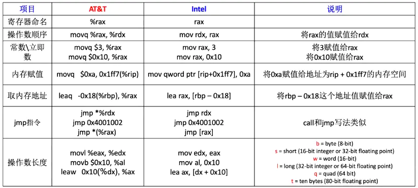
Assembly has two writing formats according to different compilers:
(1) Intel: Windows faction
(2) At & T: Unix faction
Here is a brief introduction to the differences between the two.
Let's take a look at the commonly used instructions.
The following is the writing method of at & T assembly. The two writing methods are different as follows.
1. Data transfer instruction
Transfer data from one place to another.
1.1 mov instruction
When we introduce the mov instruction, we introduce it completely, because the mov instruction is the instruction with the highest frequency, and there are many suffixes in the mnemonic.
There are three forms of mov instructions, as follows:
mov   #Ordinary move instruction
movs  #The symbolic extended move instruction symbol extends the source operand and transfers it to a 64 bit register or storage unit. movs means symbol extension
movz  #The zero extended move instruction transfers the source operand to a 64 bit register or storage unit after zero expansion. movz means zero extension
A letter after the mov instruction indicates the size of the operand in the following form:
movb #Complete 1 byte copy
movw #Complete 2-byte copy
movl #Complete 4-byte copy
movq #Complete 8-byte copy
There is another instruction, as follows:
movabsq I,R
Unlike movq, it stores a 64 bit value directly into a 64 bit register.
The form of movs instruction is as follows:
movsbw #Copy 1 byte as symbol extension to 2 bytes
movsbl #Copy 1 byte as symbol extension to 4 bytes
movsbq #Copy 1 byte as symbol extension to 8 bytes
movswl #2 bytes for symbol expansion are copied to 4 bytes
movswq #2 bytes for symbol expansion are copied to 8 bytes
movslq #4 bytes for symbol expansion are copied to 8 bytes
The form of movz instruction is as follows:
movzbw #Copy 1 byte extended by 0 to 2 bytes
movzbl #Copy 1 byte extended by 0 to 4 bytes
movzbq #Copy 1 byte extended by 0 to 8 bytes
movzwl #Copy 2 bytes extended by 0 to 4 bytes
movzwq #Copy 2 bytes extended by 0 to 8 bytes
movzlq #Copy 4 bytes extended by 0 to 8 bytes
An example is as follows:
movl   %ecx,%eax
movl   (%ecx),%eax
The first instruction copies the value in register ecx to eax register; The second instruction accesses the memory with the data in ecx register as the address, and loads the data in memory into eax register.
1.2 cmov instruction
The format of cmov instruction is as follows:
cmovxx
Where xx represents one or more letters that represent the conditions that will trigger the transfer operation. The condition depends on the current value of the EFLAGS register.
The eflags registers are shown in the following figure.

Among them, the bits in the eflags register related to the cmove instruction include CF (the mathematical expression generates carry or borrow), OF (the integer value is infinite or too small), PF (the register contains error data caused by mathematical operation), SF (the result is positive rather than negative) and ZF (the result is zero).
The following table shows the unsigned conditional transfer instructions.
| Instruction pair | describe | eflags status |
| cmova/cmovnbe | Greater than / not less than or equal to | (CF or ZF) = 0 |
| cmovae/cmovnb | Greater than or equal to / not less than | CF=0 |
| cmovnc | No carry | CF=0 |
| cmovb/cmovnae | Greater than / not less than or equal to | CF=1 |
| cmovc | carry | CF=1 |
| cmovbe/cmovna | Less than or equal to / not greater than | (CF or ZF) = 1 |
| cmove/cmovz | Equal to / zero | ZF=1 |
| cmovne/cmovnz | Not equal to / not zero | ZF=0 |
| cmovp/cmovpe | Parity / parity | PF=1 |
| cmovnp/cmovpo | Non parity / parity | PF=0 |
Unsigned conditional transfer instructions rely on carry, zero, and parity flags to determine the difference between two operands.
The following table shows the signed conditional transfer instructions.
| Instruction pair | describe | eflags status |
| cmovge/cmovnl | Greater than or equal to / not less than | (SF XOR OF) = 0 |
| cmovl/cmovnge | Greater than / not greater than or equal to | (SF XOR OF) = 1 |
| cmovle/cmovng | Less than or equal to / not greater than | ((SF XOR OF) or ZF)=1 |
| cmovo | overflow | OF=1 |
| cmovno | No overflow | OF=0 |
| cmovs | Signed (negative) | SF=1 |
| cmovns | Unsigned (non negative) | SF=0 |
An example is as follows:
// Load the vlaue value into the ecx register
movl value,%ecx
// Use the cmp instruction to compare the values in ecx and ebx registers. Specifically, subtract ebx from ecx and set eflags
cmp %ebx,%ecx
// If the value of ecx is greater than ebx, use the cmova instruction to set the value of ebx to the value in ecx
cmova %ecx,%ebx
Note that the first operand of at & T assembly comes first and the second operand comes last.
1.3 push and pop instructions
The form of the push instruction is shown in the following table.
| instructions | Operand | describe |
| push | I/R/M | The PUSH instruction first reduces the ESP value and then copies the source operand to the stack. If the operand is 16 bits, esp minus 2; if the operand is 32 bits, esp minus 4 |
| pusha | The instruction pushes 16 bit general-purpose registers onto the stack sequentially (AX, CX, DX, BX, SP, BP, SI, and DI). | |
| pushad | The instruction pushes all 32-bit general-purpose registers onto the stack in the order of EAX, ECX, EDX, EBX, ESP (value before PUSHAD), EBP, ESI and EDI. |
The form of pop instruction is shown in the following table.
| instructions | Operand | describe |
| pop | R/M | The instruction first copies the contents of the stack element pointed to by ESP into a 16 bit or 32-bit operand, and then increases the ESP value. If the operand is 16 bits, esp adds 2. If the operand is 32 bits, esp adds 4 |
| popa | The instruction pops the same registers out of the stack in reverse order | |
| popad | The instruction pops the same registers out of the stack in reverse order |
1.4 xchg and xchgl
This instruction is used to exchange the values of operands. The exchange instruction XCHG is an exchange instruction for the contents between two registers, registers and memory variables. The data types of the two operands should be the same, which can be a byte, a word or a double word. The format is as follows:
xchg    R/M,R/M
xchgl   I/R,I/R,
Two operands cannot be memory variables at the same time. xchgl instruction is an old x86 instruction. It is used to exchange 4-byte values in two registers or memory addresses. Both values cannot be memory addresses. It will not set condition codes.
1.5 lea
lea calculates the actual address of the source operand and saves the result to the destination operand, which must be a general-purpose register. The format is as follows:
lea M,R
The lea (Load Effective Address) instruction loads an address into a register.
Examples are as follows:
movl  4(%ebx),%eax
leal  4(%ebx),%eax
The first instruction means that the result obtained by adding 4 to the value stored in the ebx register is accessed as the memory address, and the data stored in the memory address is loaded into the eax register.
The second instruction means that the result obtained by adding 4 to the value stored in the ebx register is stored in the eax register as a memory address.
Another example is as follows:
leaq a(b, c, d), %rax
Calculate the address a + b + c * d, and then load the final address into the register rax. You can see that it is only a simple calculation and does not refer to the registers in the source operand. This can be used as a multiplication instruction.
2. Arithmetic operation instruction
The following describes the basic operation instructions for operating signed and unsigned integers.
2.1 add and adc instructions
The format of the instruction is as follows:
add  I/R/M,R/M
adc  I/R/M,R/M
The instruction adds the two operands and saves the result in the second operand.
For the first instruction, because the register and memory have bit width restrictions, overflow may occur during addition. If the operation overflows, the Carry Flag (CF) in the flag register eflags will be set to 1.
For the second instruction, the adc instruction and the carry flag eflags.CF can be used to add 64 bit data on a 32-bit machine.
The conventional arithmetic logic operation instructions only need to extend the instructions in the original IA-32 to 64 bits. For example, addq is the addition of four words.
2.2 sub and sbb instructions
The format of the instruction is as follows:
sub I/R/M,R/M
sbb I/R/M,R/M
The instruction subtracts the first operand from the second operand, and the result is saved in the second operand.
2.3 imul and mul instructions
The format of the instruction is as follows:
imul I/R/M,R
mul  I/R/M,R
Multiply the first operand and the second operand, and write the result to the second operand. If the second operand is empty, it defaults to the eax register, and the final complete result will be stored in edx:eax.
The first instruction performs signed multiplication and the second instruction performs unsigned multiplication.
2.4 idiv and div instructions
The format of the instruction is as follows:
div   R/M
idiv  R/M
The first instruction performs unsigned division, and the second instruction performs signed division. The divisor is spliced by edx register and eax register. The divisor is specified by the first operand of the instruction. The calculated quotient is stored in eax register and the remainder is stored in edx register. As shown in the figure below.
    edx:eax
------------ = eax((commercial)... edx(Remainder)
    register
The bit widths of the data of the divisor, quotient and divisor are different during operation. The following table shows the registers used by the idiv instruction and the div instruction.
| Bit width of data | Divisor | Divisor | merchant | remainder |
| 8 bits | ax | Instruction first operand | al | ah |
| 16 bit | dx:ax | Instruction first operand | ax | dx |
| 32 bit | edx:eax | Instruction first operand | eax | edx |
idiv instructions and div instructions usually divide the divisor whose bit width is twice that of the divisor. For example, for x86-32 machines, the multiple of the general register is 32 bits, and one register cannot hold 64 bits of data, so edx stores the high 32 bits of the dividend, while eax registers store the low 32 bits of the dividend.
Therefore, in the division operation, the 32-bit data set in eax register must be extended to 64 bits including edx register, that is, signed expansion and unsigned number zero expansion.
cltd (at & T style writing) or cdq (Intel style writing) can be used for symbolic extension of edx. The format of the instruction is as follows:
cltd // Extend the data symbols in the eax register to edx:eax
cltd extends the data symbols in the eax register to edx:eax.
2.5 incl and decl instructions
The format of the instruction is as follows:
inc  R/M
dec  R/M
Adds or subtracts the data stored in the register or memory location specified by the first operand of the instruction.
2.6 negl instruction
The format of the instruction is as follows:
neg R/M
The neg instruction reverses the sign of the first operand.
3. Bit operation instruction
3.1 andl, orl and xorl instructions
The format of the instruction is as follows:
and  I/R/M,R/M
or   I/R/M,R/M
xor  I/R/M,R/M
The and instruction performs a bitwise sum operation on the second operand and the first operand, and writes the result to the second operand;
The or instruction performs a bitwise OR operation on the second operand and the first operand, and writes the result to the second operand;
xor instruction performs bitwise xor operation on the second operand and the first operand, and writes the result to the second operand;
3.2 not instruction
The format of the instruction is as follows:
not R/M
Reverses the operand bit by bit and writes the result to the operand.
3.3 sal, sar and shr commands
The format of the instruction is as follows:
sal  I/%cl,R/M  #Arithmetic shift left
sar  I/%cl,R/M  #Arithmetic shift right
shl  I/%cl,R/M  #Logical shift left
shr  I/%cl,R/M  #Logical shift right
The sal instruction shifts the second operand to the left by the number of bits specified by the first operand, and writes the result to the second operand. The low position vacated after the shift is filled with 0. The first operand of the instruction can only be an 8-bit immediate or cl register, and only the data of the lower 5 bits is meaningful. If it is higher than or equal to 6 bits, all the data in the register will be removed and become meaningless.
The sar instruction shifts the second operand to the right according to the number of bits specified by the first operand, and writes the result to the second operand. The space after the shift is extended by symbols. Like the sal instruction, the first operand of the sar instruction must be an 8-bit immediate or cl register, and only the lower 5 bits of data are meaningful.
The actions of the shl instruction and the sall instruction are exactly the same, and there is no need to distinguish them.
shr command shifts the second operand to the right according to the number of bits specified by the first operand, and writes the result to the second operand. The vacations after the shift are zero extended. Like sal instruction, the first operand of shr instruction must be an 8-bit immediate or cl register, and only the lower 5 bits of data are meaningful.
4. Process control instruction
4.1 jmp instruction
The format of the instruction is as follows:
jmp I/R
The jmp instruction unconditionally jumps the program to the destination address specified by the operand. The jmp instruction can be regarded as an instruction that sets the instruction pointer (eip register). The destination address can also be a stack of registers followed by an asterisk, which is an indirect function call. For example:
jmp *%eax
Jump the program to the address contained in eax.
4.2 conditional jump instruction
The format of conditional jump instruction is as follows:
Jcc Destination address
Where cc refers to the jump condition. If true, the program jumps to the destination address; Otherwise, execute the next instruction. The related conditional jump instructions are shown in the table below.
| instructions | forward condition | describe | instructions | forward condition | describe |
| jz | ZF=1 | Jump when is 0 | jbe | CF=1 or ZF=1 | Jump when greater than or equal to |
| jnz | ZF=0 | Jump when not 0 | jnbe | CF=0 and ZF=0 | Jump when less than or equal to |
| je | ZF=1 | Jump when equal | jg | ZF=0 and SF=OF | Jump when greater than |
| jne | ZF=0 | Jump when not equal | jng | ZF=1 or SF= OF | Jump when not greater than |
| ja | CF=0 and ZF=0 | Jump when greater than | jge | SF=OF | Jump when greater than or equal to |
| jna | CF=1 or ZF=1 | Jump when not greater than | jnge | SF!=OF | Jump when less than or equal to |
| jae | CF=0 | Jump when greater than or equal to | jl | SF!=OF | Jump when less than |
| jnae | CF=1 | Jump when less than or equal to | jnl | SF=OF | Jump when not less than |
| jb | CF=1 | Jump when greater than | jle | ZF=1 or SF= OF | Jump when less than or equal to |
| jnb | CF=0 | Jump when not greater than | jnle | ZF=0 and SF=OF | Jump when greater than or equal to |
4.3 cmp instruction
The format of cmp instruction is as follows:
cmp I/R/M,R/M
The cmp instruction sets the flag bit in the flag register eflags according to the result by comparing the difference between the second operand and the first operand. The cmp instruction is similar to the sub instruction, but the cmp instruction does not change the value of the operand.
The relationship between the operand and the set flag bit is shown in the table.
| Relationship between operands | CF | ZF | OF |
| The first operand is less than the second operand | 0 | 0 | SF |
| The first operand is equal to the second operand | 0 | 1 | 0 |
| The first operand is greater than the second operand | 1 | 0 | not SF |
4.4 test instruction
The format of the instruction is as follows:
test I/R/M,R/M
The instruction sets the flag bit in the flag register eflags according to the result by comparing the logical sum of the first operand and the second operand. The test instruction is essentially the same as the and instruction, except that the test instruction does not change the value of the operand.
After the test instruction is executed, CF and OF are usually cleared, and ZF and SF are set according to the operation results. When the operation result is zero, ZF is set to 1, and SF is the same as the highest value.
An example is as follows:
The test instruction can check several bits at the same time. If you want to know whether bit 0 and bit 3 of AL register are set to 1, you can use the following instructions:
test al,00001001b #The mask is 0000 1001. Test whether bits 0 and 3 are 1
From the following data set example, it can be inferred that the zero flag bit is set to 1 only when all test bits are cleared to 0:
0  0  1  0  0  1  0  1    <- Input value
0  0  0  0  1  0  0  1    <- Test value
0  0  0  0  0  0  0  1    <- result: ZF=0

0  0  1  0  0  1  0  0    <- Input value
0  0  0  0  1  0  0  1    <- Test value
0  0  0  0  0  0  0  0    <- result: ZF=1
The test instruction always clears the overflow AND carry flag bits, AND its method of modifying the symbol flag bit, zero flag bit AND parity flag bit is the same as that of the AND instruction.
4.5 sete instruction
Set the target operand to 0 or 1 according to the status flags (CF,SF,OF,ZF, and PF) in eflags. The destination operand here points to a byte register (that is, an 8-bit register, such as AL, BL, CL) or a byte in memory. The status code suffix (cc) indicates the condition to be tested.
The format of the instruction to obtain the flag bit is as follows:
setcc R/M
The instruction sets the operand to 0 or 1 according to the value of the flag register eflags.
cc in setcc is similar to cc in Jcc. Refer to table.
4.6 call instruction
The format of the instruction is as follows:
call I/R/M
The call instruction calls the function specified by the operand. The call instruction will stack the address of the next instruction of the instruction, and then jump to the address specified by the operand, so that the function can return from the sub function by jumping to the address on the stack. amount to
push %eip
jmp addr
First press the next address of the instruction, and then jump to the target address addr.
4.7 ret instruction
The format of the instruction is as follows:
ret
The ret instruction is used to return from a child function. In Linux of X86 architecture, the return value of the function is set to the eax register and returned. Equivalent to the following instructions:
popl %eip
Pop up the "address of the next instruction of the call instruction" of the call instruction stack and set it to the instruction pointer. In this way, the program can correctly return the place of the sub function.
Physically, the CALL instruction pushes its return address onto the stack, and then copies the address of the called process to the instruction pointer register. When a procedure is ready to return, its RET instruction bounces the return address from the stack back to the instruction pointer register.
4.8 enter instruction
The enter instruction initializes the ebp and esp registers to establish the stack frame required by the function parameters and local variables for the function. amount to
push   %rbp
mov    %rsp,%rbp
4.9 leave instruction
leave removes the stack frame established with the enter instruction by restoring the ebp and esp registers. amount to
mov %rbp, %rsp
pop %rbp
Point the stack pointer to the frame pointer, and then pop back up the original frame pointer to% ebp
5.0 int instruction
The format of the instruction is as follows:
int I
An interrupt that causes a given number. This is usually used for system calls and other kernel interfaces.
5. Flag operation
The flag bits of the eflags register are shown in the figure below.
Some instructions that operate on the eflags register flag are shown in the following table.
| instructions | Operand | describe |
| pushfd | R | The PUSHFD instruction pushes the contents of the 32-bit EFLAGS register onto the stack |
| popfd | R | The POPFD instruction pops the contents of the top unit of the stack to the EFLAGS register |
| cld | Set eflags.df to 0 |
Part 19 - load and store instructions (1)
TemplateInterpreterGenerator::generate_ The all() function generates many routines (i.e. machine instruction fragments, called Stub in English), including calling set_ entry_ points_ for_ all_ The bytes() function generates routines corresponding to each byte code.
It will eventually call templateinterpretergenerator:: generate_ and_ The call stack of the dispatch() function is as follows:
TemplateTable::geneate()                                templateTable_x86_64.cpp
TemplateInterpreterGenerator::generate_and_dispatch()   templateInterpreter.cpp
TemplateInterpreterGenerator::set_vtos_entry_points()   templateInterpreter_x86_64.cpp
TemplateInterpreterGenerator::set_short_entry_points()  templateInterpreter.cpp
TemplateInterpreterGenerator::set_entry_points()        templateInterpreter.cpp
TemplateInterpreterGenerator::set_entry_points_for_all_bytes()   templateInterpreter.cpp
TemplateInterpreterGenerator::generate_all()            templateInterpreter.cpp
InterpreterGenerator::InterpreterGenerator()            templateInterpreter_x86_64.cpp
TemplateInterpreter::initialize()                       templateInterpreter.cpp
interpreter_init()                                      interpreter.cpp
init_globals()                                          init.cpp
Many functions on the call stack have been described earlier. Each bytecode will specify a generator function through the Template_ The gen attribute is saved. Call in TemplateTable::generate() function. Gen generates machine instruction fragments corresponding to each bytecode, so it is very important.
First look at a very simple nop bytecode instruction. The template attributes of this instruction are as follows:
// Java spec bytecodes  ubcp|disp|clvm|iswd  in    out   generator   argument
def(Bytecodes::_nop   , ____|____|____|____, vtos, vtos, nop        ,  _      );
The generation function generator of nop bytecode instructions will not generate any machine instructions, so there is only logic cached at the top of the stack in the assembly code corresponding to nop bytecode instructions. Call set_ vtos_ entry_ The assembly code generated by the points() function is as follows:
// aep
0x00007fffe1027c00: push   %rax
0x00007fffe1027c01: jmpq   0x00007fffe1027c30

// fep
0x00007fffe1027c06: sub    $0x8,%rsp
0x00007fffe1027c0a: vmovss %xmm0,(%rsp)
0x00007fffe1027c0f: jmpq   0x00007fffe1027c30

// dep
0x00007fffe1027c14: sub    $0x10,%rsp
0x00007fffe1027c18: vmovsd %xmm0,(%rsp)
0x00007fffe1027c1d: jmpq   0x00007fffe1027c30

// lep
0x00007fffe1027c22: sub    $0x10,%rsp
0x00007fffe1027c26: mov    %rax,(%rsp)
0x00007fffe1027c2a: jmpq   0x00007fffe1027c30

// bep cep sep iep
0x00007fffe1027c2f: push   %rax

// vep

// Next is the fetch logic. The starting address is 0x00007fffe1027c30
As you can see, due to tos_in is vtos, so if it is aep, bep, cep, sep and iep, directly use the push instruction to push the top cache value stored in% rax into the expression stack. For fep, dep and lep, the corresponding memory size is opened on the stack, and then the value in the register is stored on the top of the expression stack, which has the same effect as the push instruction.
In set_ vtos_ entry_ Generate is called in the points() function_ and_ The dispatch() function generates the machine instruction fragment of the nop instruction and the machine instruction fragment of the next bytecode instruction. nop does not generate any machine instructions, and the fragments referred to are as follows:
// movzbl transfers the byte with zero extension to the doubleword with the address 0x00007fffe1027c30
0x00007fffe1027c30: movzbl  0x1(%r13),%ebx

0x00007fffe1027c35: inc %r13

0x00007fffe1027c38: movabs $0x7ffff73ba4a0,%r10

// The source operand of movabs can only be an immediate or label (intrinsic or immediate), and the destination operand is a register
0x00007fffe1027c42: jmpq *(%r10,%rbx,8)
r13 refers to the address of the bytecode instruction currently to be fetched. Then% r13+1 skips the current nop instruction and points to the address of the next bytecode instruction, and then executes the movzbl instruction to load the pointed Opcode into% ebx.
The jump address through jmpq is% r10+%rbx*8. This jump address has been described in detail above and will not be introduced here.
We explained the nop instruction and reviewed the logic of stack top cache and fetch logic. For each bytecode instruction, there will be stack top cache and fetch logic. These two logics will not be introduced later when introducing bytecode instructions.
The bytecode instructions for loading storage related operations are shown in the following table.
| Bytecode | Auxiliary word sign | Instruction meaning |
| 0x00 | nop | Don't do anything? |
| 0x01 | aconst_null | Push null to the top of the stack |
| 0x02 | iconst_m1 | Push int type - 1 to the top of the stack |
| 0x03 | iconst_0 | Push int type 0 to the top of the stack |
| 0x04 | iconst_1 | Push int type 1 to the top of the stack |
| 0x05 | iconst_2 | Push int type 2 to the top of the stack |
| 0x06 | iconst_3 | Push int type 3 to the top of the stack |
| 0x07 | iconst_4 | Push int type 4 to the top of the stack |
| 0x08 | iconst_5 | Push int type 5 to the top of the stack |
| 0x09 | lconst_0 | Push long type 0 to the top of the stack |
| 0x0a | lconst_1 | Push long type 1 to the top of the stack |
| 0x0b | fconst_0 | Push float type 0 to the top of the stack |
| 0x0c | fconst_1 | Push float type 1 to the top of the stack |
| 0x0d | fconst_2 | Push float type 2 to the top of the stack |
| 0x0e | dconst_0 | Push double type 0 to the top of the stack |
| 0x0f | dconst_1 | Push double type 1 to the top of the stack |
| 0x10 | bipush | Push the single byte constant value (- 128 ~ 127) to the top of the stack |
| 0x11 | sipush | Push a short integer constant value (- 32768 ~ 32767) to the top of the stack |
| 0x12 | ldc | Push int, float or String constant values from the constant pool to the top of the stack |
| 0x13 | ldc_w | Push int, float or String constant values from the constant pool to the top of the stack (wide index) |
| 0x14 | ldc2_w | Push long or double constant values from the constant pool to the top of the stack (wide index) |
| 0x15 | iload | Push the specified int local variable to the top of the stack |
| 0x16 | lload | Push the specified long local variable to the top of the stack |
| 0x17 | fload | Push the specified float type local variable to the top of the stack |
| 0x18 | dload | Push the specified double local variable to the top of the stack |
| 0x19 | aload | Pushes the local variable of the specified reference type to the top of the stack |
| 0x1a | iload_0 | Push the first int local variable to the top of the stack |
| 0x1b | iload_1 | Push the second int local variable to the top of the stack |
| 0x1c | iload_2 | Push the third int local variable to the top of the stack |
| 0x1d | iload_3 | Push the fourth int local variable to the top of the stack |
| 0x1e | lload_0 | Push the first long local variable to the top of the stack |
| 0x1f | lload_1 | Push the second long local variable to the top of the stack |
| 0x20 | lload_2 | Push the third long local variable to the top of the stack |
| 0x21 | lload_3 | Push the fourth long local variable to the top of the stack |
| 0x22 | fload_0 | Push the first float type local variable to the top of the stack |
| 0x23 | fload_1 | Push the second float type local variable to the top of the stack |
| 0x24 | fload_2 | Push the third float type local variable to the top of the stack |
| 0x25 | fload_3 | Push the fourth float type local variable to the top of the stack |
| 0x26 | dload_0 | Push the first double local variable to the top of the stack |
| 0x27 | dload_1 | Push the second double local variable to the top of the stack |
| 0x28 | dload_2 | Push the third double local variable to the top of the stack |
| 0x29 | dload_3 | Push the fourth double local variable to the top of the stack |
| 0x2a | aload_0 | Push the first reference type local variable to the top of the stack |
| 0x2b | aload_1 | Push the second reference type local variable to the top of the stack |
| 0x2c | aload_2 | Push the third reference type local variable to the top of the stack |
| 0x2d | aload_3 | Push the fourth reference type local variable to the top of the stack |
| 0x2e | iaload | Pushes the value of the specified index of an int array to the top of the stack |
| 0x2f | laload | Push the value of the specified index of the long array to the top of the stack |
| 0x30 | faload | Push the value of the specified index of the float array to the top of the stack |
| 0x31 | daload | Push the value of the specified index of the double array to the top of the stack |
| 0x32 | aaload | Pushes the value of the specified index of the reference array to the top of the stack |
| 0x33 | baload | Push the value of the specified index of a boolean or byte array to the top of the stack |
| 0x34 | caload | Push the value of the specified index of char array to the top of the stack |
| 0x35 | saload | Push the value of the specified index of the short array to the top of the stack |
| 0x36 | istore | Store the int value at the top of the stack into the specified local variable |
| 0x37 | lstore | Store the long value at the top of the stack into the specified local variable |
| 0x38 | fstore | Store the float type value at the top of the stack into the specified local variable |
| 0x39 | dstore | Store the double value at the top of the stack into the specified local variable |
| 0x3a | astore | Store the stack top reference value into the specified local variable |
| 0x3b | istore_0 | Store the int value at the top of the stack into the first local variable |
| 0x3c | istore_1 | Store the int value at the top of the stack into the second local variable |
| 0x3d | istore_2 | Store the int value at the top of the stack into the third local variable |
| 0x3e | istore_3 | Store the int value at the top of the stack into the fourth local variable |
| 0x3f | lstore_0 | Store the long value at the top of the stack into the first local variable |
| 0x40 | lstore_1 | Store the long value at the top of the stack into the second local variable |
| 0x41 | lstore_2 | Store the long value at the top of the stack into the third local variable |
| 0x42 | lstore_3 | Store the long value at the top of the stack into the fourth local variable |
| 0x43 | fstore_0 | Store the float type value at the top of the stack into the first local variable |
| 0x44 | fstore_1 | Store the float type value at the top of the stack into the second local variable |
| 0x45 | fstore_2 | Store the float type value at the top of the stack into the third local variable |
| 0x46 | fstore_3 | Store the float type value at the top of the stack into the fourth local variable |
| 0x47 | dstore_0 | Store the double value at the top of the stack into the first local variable |
| 0x48 | dstore_1 | Store the double value at the top of the stack into the second local variable |
| 0x49 | dstore_2 | Store the double value at the top of the stack into the third local variable |
| 0x4a | dstore_3 | Store the double value at the top of the stack into the fourth local variable |
| 0x4b | astore_0 | Store the stack top reference value into the first local variable |
| 0x4c | astore_1 | Store the stack top reference value into the second local variable |
| 0x4d | astore_2 | Store the stack top reference value into the third local variable |
| 0x4e | astore_3 | Store the stack top reference value into the fourth local variable |
| 0x4f | iastore | Stores the int value at the top of the stack into the specified index position of the specified array |
| 0x50 | lastore | Store the long value at the top of the stack into the specified index position of the specified array |
| 0x51 | fastore | Store the float type value at the top of the stack into the specified index position of the specified array |
| 0x52 | dastore | Stores the double type value at the top of the stack into the specified index position of the specified array |
| 0x53 | aastore | Stores the stack top reference value into the specified index position of the specified array |
| 0x54 | bastore | Stores the boolean or byte type value at the top of the stack into the specified index position of the specified array |
| 0x55 | castore | Store the char type value at the top of the stack into the specified index position of the specified array |
| 0x56 | sastore | Store the stack top short value into the specified index position of the specified array |
| 0xc4 | wide | Instruction to expand the access index of local variable table |
We will not view the logic of the corresponding machine instruction fragment for each bytecode instruction (in fact, after decompiling the machine instruction fragment into assembly, we can understand the execution logic by viewing the assembly). The logic of some instructions is similar, and only a few typical introductions are selected here.
1. Stack type instruction
(1)aconst_null instruction
aconst_null means to send null to the top of the stack. The template is defined as follows:
def(Bytecodes::_aconst_null , ____|____|____|____, vtos, atos, aconst_null , _ );
The assembly code of the instruction is as follows:
// The xor instruction performs a logical xor operation between the corresponding bits of two operands and stores the result in the target operand
// If the first operand and the second operand are the same, the XOR operation is equivalent to the zeroing operation
xor    %eax,%eax
Due to tos_out is atos, so the results at the top of the stack are cached in the% eax register. Just perform xor operation on the% eax register.
(2)iconst_m1 instruction
iconst_m1 means to press - 1 into the stack. The template is defined as follows:
def(Bytecodes::_iconst_m1 , ____|____|____|____, vtos, itos, iconst , -1 );
After the generated machine instructions are disassembled, the assembly code is as follows:
mov $0xffffffff,%eax
Others are related to iconst_m1 bytecode instruction is similar to bytecode instruction, such as iconst_0,iconst_1. The template is defined as follows:
def(Bytecodes::_iconst_m1           , ____|____|____|____, vtos, itos, iconst              , -1           );
def(Bytecodes::_iconst_0            , ____|____|____|____, vtos, itos, iconst              ,  0           );
def(Bytecodes::_iconst_1            , ____|____|____|____, vtos, itos, iconst              ,  1           );
def(Bytecodes::_iconst_2            , ____|____|____|____, vtos, itos, iconst              ,  2           );
def(Bytecodes::_iconst_3            , ____|____|____|____, vtos, itos, iconst              ,  3           );
def(Bytecodes::_iconst_4            , ____|____|____|____, vtos, itos, iconst              ,  4           );
def(Bytecodes::_iconst_5            , ____|____|____|____, vtos, itos, iconst              ,  5           );
You can see that the generating functions are the same TemplateTable::iconst() function.
iconst_ The assembly code of 0 is as follows:
xor %eax,%eax
iconst_@ The assembly code corresponding to the bytecode instruction (@ is 1, 2, 3, 4, 5) is as follows:
// aep
0x00007fffe10150a0: push   %rax
0x00007fffe10150a1: jmpq   0x00007fffe10150d0

// fep
0x00007fffe10150a6: sub    $0x8,%rsp
0x00007fffe10150aa: vmovss %xmm0,(%rsp)
0x00007fffe10150af: jmpq   0x00007fffe10150d0

// dep
0x00007fffe10150b4: sub    $0x10,%rsp
0x00007fffe10150b8: vmovsd %xmm0,(%rsp)
0x00007fffe10150bd: jmpq   0x00007fffe10150d0

// lep
0x00007fffe10150c2: sub    $0x10,%rsp
0x00007fffe10150c6: mov    %rax,(%rsp)
0x00007fffe10150ca: jmpq   0x00007fffe10150d0

// bep/cep/sep/iep
0x00007fffe10150cf: push   %rax

// vep
0x00007fffe10150d0 mov $0x@,%eax // @For 1, 2, 3, 4, 5
If you read the article I wrote before, you should be able to understand the assembly code above. I won't introduce it too much here.
(3)bipush
bipush pushes a single byte constant value to the top of the stack. The template is defined as follows:
def(Bytecodes::_bipush , ubcp|____|____|____, vtos, itos, bipush , _ );
The assembly code of the instruction is as follows:
// %r13 refers to the address of bytecode instruction, offset by 1 bit
// After that, take out 1 byte of content and store it in% eax
movsbl 0x1(%r13),%eax
Due to tos_out is itos, so the constant value of single byte is stored in% eax, which is specially used for stack top cache.
(4)sipush
sipush pushes a short integer constant value to the top of the stack. The template is defined as follows:
def(Bytecodes::_bipush , ubcp|____|____|____, vtos, itos, bipush , _ );
The generated assembly code is as follows:
// movzwl transmission makes symbol extension word to double word
movzwl 0x1(%r13),%eax
// bswap exchanges the values of 32 / 64 bit registers in low and high bytes in bytes
bswap  %eax
// The (arithmetic shift right) instruction shifts the destination operand to the arithmetic right
sar    $0x10,%eax
Short integers in Java occupy 2 bytes, so some operations need to be done on the 32-bit register%eax. Since the bytecode adopts large end storage, it is uniformly transformed into small end storage during processing.
2. Storage type instruction
The istore instruction will store int type values into the local variable table of the specified index. The template is defined as follows:
def(Bytecodes::_istore , ubcp|____|clvm|____, itos, vtos, istore , _ );
The generating function is TemplateTable::istore(), and the generated assembly code is as follows:
movzbl 0x1(%r13),%ebx
neg    %rbx
mov    %eax,(%r14,%rbx,8)
Due to stack top cache tos_in is itos, so the value in% eax is directly stored in the local variable table of the specified index.
Specify ubcp in the template because% r13, that is, bytecode instruction pointer, will be used in the generated assembly code.
The assembly code logic of other byte code instructions such as istore and dstore is also similar, but it is not introduced here.
Part 20 - ldc and of load and store instructions_ fast_aldc instruction (2)
The ldc instruction pushes int, float, or a symbolic reference of a class, method type or method handle, and possibly a String constant value from the constant pool to the top of the stack.
This article introduces a bytecode instruction ldc defined in a virtual machine specification, and another bytecode instruction used inside the virtual machine_ fast_aldc. The ldc instruction can load the symbolic reference of String, method type or method handle. However, if you want to load the symbolic reference of String, method type or method handle, the ldc bytecode instruction will be rewritten as the bytecode instruction used inside the virtual machine during class connection_ fast_aldc. Next, we describe in detail how the ldc instruction loads data of int, float and class types, and_ fast_aldc loads String, method type or method handle, and why byte code rewriting is needed.
1. ldc bytecode instruction
The ldc instruction pushes int, float, or String constant values from the constant pool to the top of the stack. The template is defined as follows:
def(Bytecodes::_ldc , ubcp|____|clvm|____, vtos, vtos, ldc , false );
The format of the ldc bytecode instruction is as follows:
// Index is an unsigned byte type data indicating the index of the runtime constant pool of the current class
ldc index
Call the generation function TemplateTable::ldc(bool wide). The assembly code generated by the function is as follows:
Part 1 Code:
// The movzbl instruction copies a byte and fills its destination with 0
// For the rest of the operands of, this extension method is called "zero extension"
// The format specified by ldc is ldc index, and index is one byte
0x00007fffe1028530: movzbl 0x1(%r13),%ebx // Load index to% ebx

// %rcx points to the first address of the cache pool and% rax points to the type array_ tags first address
0x00007fffe1028535: mov    -0x18(%rbp),%rcx
0x00007fffe1028539: mov    0x10(%rcx),%rcx
0x00007fffe102853d: mov    0x8(%rcx),%rcx
0x00007fffe1028541: mov    0x10(%rcx),%rax


// From_ The tags array gets the operand type and stores it in% edx
0x00007fffe1028545: movzbl 0x4(%rax,%rbx,1),%edx

// $0x64 represents the JVM_ CONSTANT_ Unresolved class, compare. If the class is not linked,
// Jump directly to call_ldc
0x00007fffe102854a: cmp    $0x64,%edx
0x00007fffe102854d: je     0x00007fffe102855d   // call_ldc

// $0x67 for JVM_ CONSTANT_ Unresolved classinerror, that is, if the class is in
// If an error occurs during the link process, jump to call_ldc
0x00007fffe102854f: cmp    $0x67,%edx
0x00007fffe1028552: je     0x00007fffe102855d  // call_ldc

// $0x7 for JVM_CONSTANT_Class, indicating that if the class has been connected, then
// Jump to notClass
0x00007fffe1028554: cmp    $0x7,%edx
0x00007fffe1028557: jne    0x00007fffe10287c0  // notClass

// If the class has no connection or an error occurs during the connection, execute the following assembly code
// -- call_ldc --
Let's take a look at calling call_ Assembly code generated by VM (rax, CAST_FROM_FN_PTR (address, interpreter Runtime:: LDC), c_rarg1) function, cast_ FROM_ FN_ PTR is a macro. After macro expansion, it is ((address_word) (interpreterruntime:: LDC)).
Calling call_ When using vm() function, the parameters passed are as follows:
- %rax now stores the first address of the type array, but it is passed in to receive the result value of the calling function
- adr is the first address of the interpreter Runtime:: ldc() function
- c_rarg1 uses the rdi register to store the wide value, which is 0 here, which means that the assembly code is generated for the ldc instruction without the prefix of wide
The generated assembly code is as follows:
Part 2:
// Move the value of wide to the% esi register for subsequent
// Call the InterpreterRuntime::ldc() function to prepare the second parameter
0x00007fffe102855d: mov $0x0,%esi
// Call MacroAssembler::call_VM() function, which calls the functions used in HotSpot VM
// The function written in C + + calls the InterpreterRuntime::ldc() function through the function written in C + +

0x00007fffe1017542: callq  0x00007fffe101754c
0x00007fffe1017547: jmpq   0x00007fffe10175df // Jump to E1

// Call MacroAssembler::call_VM_helper() function
// Set the return address stored at the top of the stack to% rax, that is, set the storage address 0x00007fffe1017547
// Set the slot address of the stack to% rax
0x00007fffe101754c: lea 0x8(%rsp),%rax


// Call InterpreterMacroAssembler::call_VM_base() function
// Store bcp to a specific location on the stack
0x00007fffe1017551: mov %r13,-0x38(%rbp)

// Call MacroAssembler::call_VM_base() function
// Move the value in r15 to the rdi register, that is, prepare the first parameter for the function call
0x00007fffe1017555: mov   %r15,%rdi
// Only the interpreter must set fp
// Set last_java_fp is saved to the last of the JavaThread class_ java_ In FP attribute
0x00007fffe1017558: mov   %rbp,0x200(%r15)
// Set last_java_sp saved to last of JavaThread class_ java_ In SP attribute
0x00007fffe101755f: mov   %rax,0x1f0(%r15)

// ... omit calling MacroAssembler::call_VM_leaf_base() function

// Reset JavaThread::last_java_sp and javathread:: last_ java_ Value of FP attribute
0x00007fffe1017589: movabs $0x0,%r10
0x00007fffe1017593: mov %r10,0x1f0(%r15)
0x00007fffe101759a: movabs $0x0,%r10
0x00007fffe10175a4: mov %r10,0x200(%r15)

// check for pending exceptions (java_thread is set upon return)
0x00007fffe10175ab: cmpq  $0x0,0x8(%r15)
// If there is no exception, jump directly to ok
0x00007fffe10175b3: je    0x00007fffe10175be
// If there is an exception, jump to stubbroutes:: forward_ exception_ Routine entry obtained by entry()
0x00007fffe10175b9: jmpq  0x00007fffe1000420

// -- ok --
// Javathread:: VM_ Store the value in the result attribute in the% rax register and empty the VM_ The value of the result property
0x00007fffe10175be: mov     0x250(%r15),%rax
0x00007fffe10175c5: movabs  $0x0,%r10
0x00007fffe10175cf: mov     %r10,0x250(%r15)

// End calling MacroAssembler::call_VM_base() function


// Restore bcp and locales
0x00007fffe10175d6: mov   -0x38(%rbp),%r13
0x00007fffe10175da: mov   -0x30(%rbp),%r14


// End calling MacroAssembler::call_VM_helper() function

0x00007fffe10175de: retq
// End calling MacroAssembler::call_VM() function
The meaning of the following compilation is explained in detail below.
The call instruction is equivalent to the following two instructions:
push %eip
jmp  addr
The ret command is equivalent to:
pop %eip
Therefore, the above assembly code:
0x00007fffe1017542: callq  0x00007fffe101754c
0x00007fffe1017547: jmpq   0x00007fffe10175df // Jump
...
0x00007fffe10175de: retq
Calling the callq instruction pushes the address of jmpq into the expression stack, that is, the return address x0007fffe1017547. In this way, when retq is called later, it will jump to the jmpq instruction execution, and jmpq will jump to the instruction execution at the address 0x00007fffe10175df.
By calling MacroAssembler::call_VM() function to call the function written in C + + in HotSpot VM, call_ The vm() function also calls the following functions:
MacroAssembler::call_VM_helper
   InterpreterMacroAssembler::call_VM_base()
       MacroAssembler::call_VM_base()
            MacroAssembler::call_VM_leaf_base()
Among the above functions, the most important one is macro assembler:: call_ VM_ Save rsp and rbp values in the base() function to JavaThread::last_java_sp and JavaThread::last_java_fp attribute, and then through macroassembler:: call_ VM_ leaf_ The assembly code generated by the base() function calls the InterpreterRuntime::ldc() function written in C + +. If the InterpreterRuntime::ldc() function is called, the values of rsp and rbp may be destroyed (the values in other registers such as% r13 and% r14 may also be damaged, so they are saved to the stack when necessary and restored after the call is completed. In this way, these registers are actually the registers saved by the caller.) Therefore, in order to ensure rsp and rbp, these two values are stored in the thread. These two values saved in the thread are very important for stack expansion, which will be described in detail later.
Since the above assembly code will be interpreted and executed, and C + + functions will be called during interpretation and execution, C/C + + stack and Java stack are mixed together, which brings us a certain complexity.
The assembly code generated by the called MacroAssembler::call_VM_leaf_base() function is as follows:
Part 3 assembly code:
// Call the MacroAssembler::call_VM_leaf_base() function
0x00007fffe1017566: test  $0xf,%esp          // Check alignment
// %esp alignment operation, jump to L
0x00007fffe101756c: je    0x00007fffe1017584
// %Operation when esp is not aligned
0x00007fffe1017572: sub   $0x8,%rsp
0x00007fffe1017576: callq 0x00007ffff66a22a2  // Call the function, that is, call the InterpreterRuntime::ldc() function
0x00007fffe101757b: add   $0x8,%rsp
0x00007fffe101757f: jmpq  0x00007fffe1017589  // Jump to E2
// -- L --
// %esp alignment operation
0x00007fffe1017584: callq 0x00007ffff66a22a2  // Call the function, that is, call the InterpreterRuntime::ldc() function

// -- E2 --

// End call
MacroAssembler::call_VM_leaf_base()function
In the above assembly, the C + + function InterpreterRuntime::ldc() will be called. As this is a C + + function, if parameters are to be passed during the call, the C + + calling convention must be observed, that is, the first six parameters are placed in fixed registers. This function requires two parameters, thread and wide, which have been put into the% rdi and% rax registers respectively. The interpreter Runtime:: ldc() function is implemented as follows:
// ldc is responsible for pushing numeric constants or String constant values from the constant pool to the top of the stack
IRT_ENTRY(void, InterpreterRuntime::ldc(JavaThread* thread, bool wide))
  ConstantPool* pool = method(thread)->constants();
  int index = wide ? get_index_u2(thread, Bytecodes::_ldc_w) : get_index_u1(thread, Bytecodes::_ldc);
  constantTag tag = pool->tag_at(index);

  Klass* klass = pool->klass_at(index, CHECK);
  oop java_class = klass->java_mirror(); // java.lang.Class is represented by oop
  thread->set_vm_result(java_class);
IRT_END
The function stores the found class of the method currently being interpreted and executed to the VM of the JavaThread class_ In the result attribute. We can go back to part 2 of the assembly code, which will_ The value of the result property is set to% rax.
Next, continue to look at the assembly code generated by the TemplateTable::ldc(bool wide) function. At this time, you have called call_ The VM () function generates a C + + assembly that calls InterpreterRuntime::ldc(). After the call is completed, the value has been put into% rax.
// -- E1 --
0x00007fffe10287ba: push   %rax  // Stores the result of the call in an expression
0x00007fffe10287bb: jmpq   0x00007fffe102885e // Jump to Done

// -- notClass --
// $0x4 indicates JVM_CONSTANT_Float
0x00007fffe10287c0: cmp    $0x4,%edx
0x00007fffe10287c3: jne    0x00007fffe10287d9 // Skip to notFloat
// When the number loaded by the ldc bytecode instruction is float, execute the following assembly code
0x00007fffe10287c5: vmovss 0x58(%rcx,%rbx,8),%xmm0
0x00007fffe10287cb: sub    $0x8,%rsp
0x00007fffe10287cf: vmovss %xmm0,(%rsp)
0x00007fffe10287d4: jmpq   0x00007fffe102885e // Jump to Done

// -- notFloat --
// When the ldc bytecode instruction loads non float, that is, int type data, it is added to the expression stack through push
0x00007fffe1028859: mov    0x58(%rcx,%rbx,8),%eax
0x00007fffe102885d: push   %rax

// -- Done --
In addition to loading String, the ldc instruction may also load int and float. If it is an int, it directly calls push to push it into the expression stack. If it is a float, it opens up space on the expression stack and then moves it to the opened slot for storage. Note that float uses the% xmm0 register.
2,fast_aldc virtual machine internal bytecode instruction
Described below_ fast_aldc instruction, which is an instruction used inside the virtual machine rather than an instruction defined in the virtual machine specification_ fast_ The template of ALDC instruction is defined as follows:
def(Bytecodes::_fast_aldc , ubcp|____|clvm|____, vtos, atos, fast_aldc , false );
The generation function is TemplateTable::fast_aldc(bool wide). The assembly code generated by this function is as follows:
// Call InterpreterMacroAssembler::get_cache_index_at_bcp() function generation
// Gets the operand of the bytecode instruction. This operand has pointed to the index of the constant pool cache entry. It is rewritten in bytecode
// Bytecode rewriting has been performed in phase
0x00007fffe10243d0: movzbl 0x1(%r13),%edx

// Call InterpreterMacroAssembler::load_resolved_reference_at_index() function generation

// shl represents a logical shift to the left, which is equivalent to multiplying by 4, because the size of the ConstantPoolCacheEntry is 4 words
0x00007fffe10243d5: shl    $0x2,%edx

// Get Method*
0x00007fffe10243d8: mov    -0x18(%rbp),%rax
// Get ConstMethod*
0x00007fffe10243dc: mov    0x10(%rax),%rax
// Get ConstantPool*
0x00007fffe10243e0: mov    0x8(%rax),%rax
// Get constantpool::_ resolved_ The value of the references property
// Is a pointer to an array of objects
0x00007fffe10243e4: mov    0x30(%rax),%rax

// JNIHandles::resolve(obj)
0x00007fffe10243e8: mov    (%rax),%rax

// From_ resolved_ Get oop at the subscript index specified by the references array, and offset the index first
0x00007fffe10243eb: add    %rdx,%rax

// 0x10 is added to% rax because the header size of the array object is 2 words
// %rax points to oop
0x00007fffe10243ee: mov    0x10(%rax),%eax
Get_ resolved_ The values of the references attribute and the two attributes involved are defined in the ConstantPool class as follows:
// Array of resolved objects from the constant pool and map from resolved
// object index to original constant pool index
jobject              _resolved_references; // jobject is a pointer type
Array<u2>*           _reference_map;
About_ resolved_references actually refers to an Object array. In constantpool:: initialize_ resolved_ This property is initialized in the references () function. The call chain is as follows:
ConstantPool::initialize_resolved_references()  constantPool.cpp
Rewriter::make_constant_pool_cache()  rewriter.cpp
Rewriter::Rewriter()                  rewriter.cpp
Rewriter::rewrite()                   rewriter.cpp
InstanceKlass::rewrite_class()        instanceKlass.cpp
InstanceKlass::link_class_impl()      instanceKlass.cpp
If you need to connect ldc and other instructions later, you may call the following functions: (we only discuss the problem of ldc loading String type data, so we only look at the _resolved_references attribute and put the oop logic representing String. MethodType and MethodHandle will not be introduced, and those interested can study it by themselves.)
oop ConstantPool::string_at_impl(
 constantPoolHandle this_oop,
 int    which,
 int    obj_index,
 TRAPS
) {
  oop str = this_oop->resolved_references()->obj_at(obj_index);
  if (str != NULL)
	  return str;

  Symbol* sym = this_oop->unresolved_string_at(which);
  str = StringTable::intern(sym, CHECK_(NULL));

  this_oop->string_at_put(which, obj_index, str);

  return str;
}

void string_at_put(int which, int obj_index, oop str) {
  // Gets the of type jobject_ resolved_ The value of the references property
  objArrayOop tmp = resolved_references();
  tmp->obj_at_put(obj_index, str);
}
In the above function_ resolved_ Sets the cached value in the references array.
The general idea is: if the ldc loads a string, try to pass it_ resolved_ Find the oop representing the string at one time in the references array. Otherwise, find the Symbol instance through the original constant pool subscript index (the Symbol instance is used internally by HotSpot VM to represent the string), generate the corresponding oop according to the Symbol instance, and then set the subscript index through the constant pool cache to_ resolved_references. When the next lookup, the oop representing the string is found through the constant pool cache subscript cache.
Get_ resolved_ After the value of the references attribute, look at the generated assembly code, as follows:
// ...
// %eax stores oop representing strings
0x00007fffe1024479: test   %eax,%eax
// If oop has been obtained, jump to resolved
0x00007fffe102447b: jne    0x00007fffe1024481

// No oop was obtained. Connection operation is required. 0xe5 yes_ fast_ Opcode of ALDC
0x00007fffe1024481: mov    $0xe5,%edx
Call_ The assembly code generated by vm() function is as follows:
// Call InterpreterRuntime::resolve_ldc() function
0x00007fffe1024486: callq  0x00007fffe1024490
0x00007fffe102448b: jmpq   0x00007fffe1024526

// Store the ConstantPoolCacheEntry entry in% rdx in the first parameter

// Call MacroAssembler::call_VM_helper() function generation
0x00007fffe1024490: mov    %rdx,%rsi
// Load return address into% rax
0x00007fffe1024493: lea    0x8(%rsp),%rax

// call_VM_base() function generation
// Save bcp
0x00007fffe1024498: mov    %r13,-0x38(%rbp)

// Call MacroAssembler::call_VM_base() function generation

// Move the value in r15 to c_rarg0(rdi) register, that is, prepare the first parameter for the function call
0x00007fffe102449c: mov    %r15,%rdi
// Only interpreter should have to set fp
0x00007fffe102449f: mov    %rbp,0x200(%r15)
0x00007fffe10244a6: mov    %rax,0x1f0(%r15)

// Call MacroAssembler::call_VM_leaf_base() generation
0x00007fffe10244ad: test   $0xf,%esp
0x00007fffe10244b3: je     0x00007fffe10244cb
0x00007fffe10244b9: sub    $0x8,%rsp
0x00007fffe10244bd: callq  0x00007ffff66b27ac
0x00007fffe10244c2: add    $0x8,%rsp
0x00007fffe10244c6: jmpq   0x00007fffe10244d0
0x00007fffe10244cb: callq  0x00007ffff66b27ac
0x00007fffe10244d0: movabs $0x0,%r10
// End calling MacroAssembler::call_VM_leaf_base()

0x00007fffe10244da: mov    %r10,0x1f0(%r15)
0x00007fffe10244e1: movabs $0x0,%r10

// Check whether there is any abnormality
0x00007fffe10244eb: mov    %r10,0x200(%r15)
0x00007fffe10244f2: cmpq   $0x0,0x8(%r15)
// If no exception occurs, jump to ok
0x00007fffe10244fa: je     0x00007fffe1024505
// If an exception occurs, jump to stubbroutes:: forward_ exception_ entry()
0x00007fffe1024500: jmpq   0x00007fffe1000420

// ---- ok ----

// Javathread:: VM_ The value in the result attribute is stored in oop_result register and empty VM_ The value of the result property
0x00007fffe1024505: mov    0x250(%r15),%rax
0x00007fffe102450c: movabs $0x0,%r10
0x00007fffe1024516: mov    %r10,0x250(%r15)

// As a result, macroassembler:: call is called_ VM_ Base() function

// Recover bcp and locales
0x00007fffe102451d: mov    -0x38(%rbp),%r13
0x00007fffe1024521: mov    -0x30(%rbp),%r14

// End calling InterpreterMacroAssembler::call_VM_base() function
// End calling MacroAssembler::call_VM_helper() function

0x00007fffe1024525: retq

// End calling MacroAssembler::call_VM() function, back to
// TemplateTable::fast_ The ALDC () function continues to look at the generated code, only
// resolved points are defined

// ---- resolved ----
Called interpreterruntime:: Resolve_ The implementation of the ldc() function is as follows:
IRT_ENTRY(void, InterpreterRuntime::resolve_ldc(
 JavaThread* thread,
 Bytecodes::Code bytecode)
) {
  ResourceMark rm(thread);
  methodHandle m (thread, method(thread));
  Bytecode_loadconstant  ldc(m, bci(thread));
  oop result = ldc.resolve_constant(CHECK);

  thread->set_vm_result(result);
}
IRT_END
This function will call a series of functions, and the related call chain is as follows:
ConstantPool::string_at_put()   constantPool.hpp
ConstantPool::string_at_impl()  constantPool.cpp
ConstantPool::resolve_constant_at_impl()     constantPool.cpp
ConstantPool::resolve_cached_constant_at()   constantPool.hpp
Bytecode_loadconstant::resolve_constant()    bytecode.cpp
InterpreterRuntime::resolve_ldc()            interpreterRuntime.cpp
Where constantpool:: String_ at_ The impl () function has been described in detail earlier.
Resolve called_ The constant() function is implemented as follows:
oop Bytecode_loadconstant::resolve_constant(TRAPS) const {
  int index = raw_index();
  ConstantPool* constants = _method->constants();
  if (has_cache_index()) {
    return constants->resolve_cached_constant_at(index, THREAD);
  } else {
    return constants->resolve_constant_at(index, THREAD);
  }
}
Resolve called_ cached_ constant_ At () or resolve_ constant_ The implementation of at() function is as follows:
oop resolve_cached_constant_at(int cache_index, TRAPS) {
    constantPoolHandle h_this(THREAD, this);
    return resolve_constant_at_impl(h_this, _no_index_sentinel, cache_index, THREAD);
}

oop resolve_possibly_cached_constant_at(int pool_index, TRAPS) {
    constantPoolHandle h_this(THREAD, this);
    return resolve_constant_at_impl(h_this, pool_index, _possible_index_sentinel, THREAD);
}
Resolve called_ constant_ at_ The impl() function is implemented as follows:
oop ConstantPool::resolve_constant_at_impl(
 constantPoolHandle this_oop,
 int index,
 int cache_index,
 TRAPS
) {
  oop result_oop = NULL;
  Handle throw_exception;

  if (cache_index == _possible_index_sentinel) {
    cache_index = this_oop->cp_to_object_index(index);
  }

  if (cache_index >= 0) {
    result_oop = this_oop->resolved_references()->obj_at(cache_index);
    if (result_oop != NULL) {
      return result_oop;
    }
    index = this_oop->object_to_cp_index(cache_index);
  }

  jvalue prim_value;  // temp used only in a few cases below

  int tag_value = this_oop->tag_at(index).value();

  switch (tag_value) {
  // ...
  case JVM_CONSTANT_String:
    assert(cache_index != _no_index_sentinel, "should have been set");
    if (this_oop->is_pseudo_string_at(index)) {
      result_oop = this_oop->pseudo_string_at(index, cache_index);
      break;
    }
    result_oop = string_at_impl(this_oop, index, cache_index, CHECK_NULL);
    break;
  // ...
  }

  if (cache_index >= 0) {
    Handle result_handle(THREAD, result_oop);
    MonitorLockerEx ml(this_oop->lock());
    oop result = this_oop->resolved_references()->obj_at(cache_index);
    if (result == NULL) {
      this_oop->resolved_references()->obj_at_put(cache_index, result_handle());
      return result_handle();
    } else {
      return result;
    }
  } else {
    return result_oop;
  }
}
Judging from the tags array of the constant pool, if the JVM is stored at the subscript index of the constant pool_ CONSTANT_ String constant pool item, call string_at_impl() function, which has been introduced before, will create oop representing the string according to the Symbol instance representing the string. In constantpool:: Resolve_ constant_ at_ After oop is obtained in impl() function, it is stored in constantpool::_ resolved_ In the references attribute, this oop is finally returned, which is exactly the oop required by the ldc.
By overriding fast_aldc bytecode instructions achieve the purpose of directly obtaining oop through a small number of instructions, and oop is cached, so the representation of string constants in HotSpot VM is unique, that is, there is only one oop representation.
The returned value of C + + function convention will be stored in% rax according to_ fast_ According to the template definition of ALDC bytecode instruction, tos_out is atos, so no further operation is required.
HotSpot VM rewrites some bytecodes during class connection, such as ldc bytecode rewriting to fast_aldc, tag type array of constant pool, constant pool cache and other contents have been introduced in detail in in in-depth analysis of Java virtual machine: source code analysis and example explanation, which will not be introduced here.
Part 21 - ldc and of load and store instructions_ fast_aldc instruction (3)
iload pushes local variables of type int to the top of the stack. The template is defined as follows:
def(Bytecodes::_iload , ubcp|____|clvm|____, vtos, itos, iload , _ );
The format of the iload instruction is as follows:
iload index
Index is an unsigned byte type integer that points to the index value of the local variable table.
The generating function is TemplateTable::iload(). The decompiled assembly code is as follows:
// Points% ebx to the first address of the next bytecode instruction
0x00007fffe1028d30: movzbl 0x2(%r13),%ebx
// $0x15 is_ The opcode value of the iload instruction
0x00007fffe1028d35: cmp $0x15,%ebx
// When the next instruction is iload, jump directly to done
0x00007fffe1028d38: je 0x00007fffe1028deb // done

// 0xdf is_ fast_ The opcode value of the Iload instruction
0x00007fffe1028d3e: cmp $0xdf,%ebx
// Will_ fast_iload2 instruction moved to% ecx
0x00007fffe1028d44: mov $0xe0,%ecx
0x00007fffe1028d49: je 0x00007fffe1028d5a // rewrite

// 0x34 is_ The opcode of the caload instruction
// _ The caload instruction means to load a char type data from the array to the operand stack
0x00007fffe1028d4b: cmp $0x34,%ebx
// Will_ fast_icaload moved to% ecx
0x00007fffe1028d4e: mov $0xe1,%ecx
0x00007fffe1028d53: je 0x00007fffe1028d5a // rewrite

// Will_ fast_iload moved to% ecx
0x00007fffe1028d55: mov $0xdf,%ecx

// -- rewrite --

// Call patch_bytecode() function
// Rewrite to fast version, because the fast version of bytecode is stored in% cl, and the 8 bits of% ecx are called% cl
0x00007fffe1028de7: mov %cl,0x0(%r13)

// -- done --

// Gets the operand of the bytecode instruction, which is the index of the local variable table
0x00007fffe1028deb: movzbl 0x1(%r13),%ebx
0x00007fffe1028df0: neg %rbx
// Load values from the local variable table into% eax through the local variable table index,
// %What is stored in eax is the cache value at the top of the stack, so there is no need to push it into the stack
0x00007fffe1028df3: mov (%r14,%rbx,8),%eax
The logic of execution is as follows:
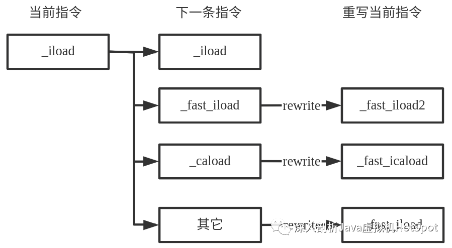
Suppose that the bytecode instruction stream of a method is to connect three iload instructions, and the front and back of the three iload instructions are non iload instructions. The rewriting process is as follows:
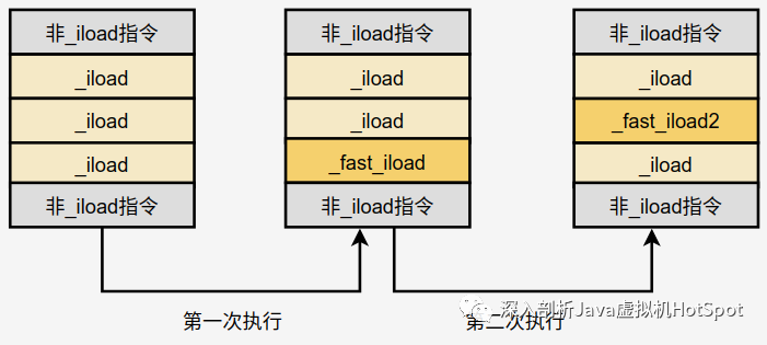
When the assembly code is executed for the first time, if the last one is judged_ Right and wrong after Iload_ The Iload instruction overrides the last one_ The Iload instruction is_ fast_iload; In the second execution, when the second bytecode instruction is_ Iload, and then it is judged as_ fast_ When Iload, the second is updated_ Iload is_ fast_iload2.
Execute_ fast_iload and execution_ fast_iload2 can improve the efficiency of program execution_ fast_ The icaload instruction is the same. These instructions are described in detail below.
1,_ fast_iload instruction
_ fast_iload pushes local variables of type int to the top of the stack. The template is defined as follows:
def(Bytecodes::_fast_iload , ubcp|____|____|____, vtos, itos, fast_iload , _ );
The generation function is TemplateTable::fast_iload(), assembly code is as follows:
0x00007fffe1023f90: movzbl 0x1(%r13),%ebx
0x00007fffe1023f95: neg %rbx
0x00007fffe1023f98: mov (%r14,%rbx,8),%eax
Assembly code is very simple. I won't say too much here.
Execute_ fast_iload instruction and execution_ Compared with the iload instruction, it does not need to make so many judgments introduced in the previous assembly, nor does it have rewritten logic, so it will improve the execution efficiency.
2,_ fast_iload2 instruction
_ fast_iload2 pushes local variables of type int to the top of the stack. The template is defined as follows:
def(Bytecodes::_fast_iload2 , ubcp|____|____|____, vtos, itos, fast_iload2 , _ );
The generation function is TemplateTable::fast_iload2(), assembly code is as follows:
0x00007fffe1024010: movzbl 0x1(%r13),%ebx
0x00007fffe1024015: neg %rbx
0x00007fffe1024018: mov (%r14,%rbx,8),%eax
0x00007fffe102401c: push %rax
0x00007fffe102401d: movzbl 0x3(%r13),%ebx
0x00007fffe1024022: neg %rbx
0x00007fffe1024025: mov (%r14,%rbx,8),%eax
It can be seen that this instruction is equivalent to executing the iload instruction twice in a row, eliminating the instruction jump, so the efficiency should be higher.
3,_ fast_icaload instruction
The caload instruction means to load a char type data from the array to the operand stack.
_ fast_icaload will push the value of the specified index of the char type array to the top of the stack. The template is defined as follows:
def(Bytecodes::_fast_icaload , ubcp|____|____|____, vtos, itos, fast_icaload , _ );
The generation function is TemplateTable::fast_icaload(), the generated assembly code is as follows:
0x00007fffe1024090: movzbl 0x1(%r13),%ebx
0x00007fffe1024095: neg %rbx
// %index is stored in eax
0x00007fffe1024098: mov (%r14,%rbx,8),%eax
// %arrayref is stored in rdx
0x00007fffe102409c: pop %rdx
// A double word is extended and sent to a four word. index is stored in% rax
0x00007fffe102409d: movslq %eax,%rax
// %rdx points to the first address of the array object and gets the value of the length attribute after offset 0xc
0x00007fffe10240a0: cmp 0xc(%rdx),%eax
0x00007fffe10240a3: mov %eax,%ebx
// Jump if the array index is equal to or greater than the length of the array
// To_ throw_ ArrayIndexOutOfBoundsException_ The entry threw an exception
0x00007fffe10240a5: jae 0x00007fffe100ff20
// Loads the value of index at the specified index in the specified array arrayref
0x00007fffe10240ab: movzwl 0x10(%rdx,%rax,2),%eax
It can be seen that this instruction eliminates the instruction jump, so it is more efficient.
Due to the word limit, the template interpreter interprets and executes Java bytecode instructions (Part 2) will be released in the next chapter