In the computer three-dimensional world, if you want to simulate a real object and make its surface look more realistic, you need to use the "texture mapping" technology. In short, it is a way to map 2D images onto 3D objects. Generally speaking, texture is one or more 2D images representing the surface details of an object, also known as texture map. When we map the texture map to the object surface in a specific way, it can make the object look closer to reality. In fact, we can think of the texture as the pixel color applied to the object surface.
Direct3D texture map supports multiple formats of images, including. jpg,. bmp,. dds,. png, etc., and the size of images is generally N-power square pictures with side length of 2, such as 128 * 128256 * 256512 * 5121024 * 1024, etc. The texture map stores the color value of each point through a two-dimensional array, which is called texture element. Each texture element has a unique two-dimensional coordinate in the texture coordinate system. In order to map the texture map to the three-dimensional model, Direct3D uses the corresponding texture coordinates in the vertex structure to determine each texture element on the texture map. Texture coordinates are specified by a two-dimensional coordinate system, which is composed of the u axis along the horizontal direction and the v axis along the vertical direction. Together, they are a pair of coordinates (u,v). In fact, it is a concept different from the (x,y) coordinate pair we are used to, but the expression is different. The value orientation of texture coordinates is between [0,1], the upper left corner is (0,0), and the lower right corner is (1,1). This is one reason why texture maps are square.
In order to demonstrate the texture mapping technology, we use VS2019 to create a new project "D3D_05_Texture" and copy the previous code. First, we declare the global variable, and the code is as follows:
// Direct3D device pointer object
LPDIRECT3DDEVICE9 D3DDevice = NULL;

// Mouse position
int mx = 0, my = 0;

// Define FVF flexible vertex format structure
struct D3D_DATA_VERTEX { FLOAT x, y, z, u, v; };

// Defines the vertex type that contains the texture
#define D3D_FVF_VERTEX (D3DFVF_XYZ | D3DFVF_TEX1)

// Vertex Buffer Objects
LPDIRECT3DVERTEXBUFFER9 D3DVertexBuffer = NULL;

// Texture object
LPDIRECT3DTEXTURE9 D3DTexture = NULL;
Please note that texture coordinates (u,v) are included when defining vertex structure and type. In order to briefly illustrate the use of texture, in this case, we create a quadrilateral and assign an image with a size of 512 * 512 to the quadrilateral. Because the quadrilateral exactly corresponds to the square image, that is, the UV coordinates of the upper left corner of the quadrilateral are (0,0), and the UV coordinates of the lower right corner of the quadrilateral are (1,1). In this case, the square image is tiled on the quadrilateral. First, we need to organize the quadrilateral vertex data in the initScene function. The code is as follows:
// Initializing Quad vertex array data
//
//	V1 *********** V2
//	    *       * *
//      *     *   *
//      *   *     *
//      * *       *
//	V0 *********** V3
//
D3D_DATA_VERTEX vertexArray[] =
{
	// Triangle V0V1V2, lower left corner clockwise
	{ -10.0f,  -10.0f, 0.0f, 0.0f, 1.0f },	// Lower left UV coordinates (0,1)
	{ -10.0f,  10.0f, 0.0f, 0.0f, 0.0f },	// Upper left UV coordinates (0,0)
	{  10.0f,  10.0f, 0.0f, 1.0f, 0.0f },	// Upper right UV coordinates (1,0)

	// Triangle V0V2V3, lower left corner clockwise
	{ -10.0f,  -10.0f, 0.0f, 0.0f, 1.0f },	// Lower left UV coordinates (0,1)
	{  10.0f,  10.0f, 0.0f, 1.0f, 0.0f },	// Upper right UV coordinates (1,0)
	{  10.0f,  -10.0f, 0.0f, 1.0f, 1.0f },	// UV coordinates in the lower right corner (1,1)
};

// Create vertex buffer object
D3DDevice->CreateVertexBuffer(sizeof(vertexArray),0,D3D_FVF_VERTEX,D3DPOOL_DEFAULT,&D3DVertexBuffer,NULL);

// Fill vertex buffer object
void* ptr;
D3DVertexBuffer->Lock(0,sizeof(vertexArray),(void**)&ptr,0);
memcpy(ptr, vertexArray, sizeof(vertexArray));
D3DVertexBuffer->Unlock();
If we want to texture map the object surface, we must first create a texture object. We can use the D3DXCreateTexture function in the D3DX library to create a texture object. But more often, the texture is read from the file, that is, the D3DXCreateTextureFromFile method is used. There is another enhanced version of D3DXCreateTextureFromFileEx, which can not only reload and create the texture object from the image, but also specify the width, height and other attribute information of the texture object. After the texture object is generated, you can call the SetTexture method to set the texture that needs to be enabled at present. The process of creating texture objects is generally placed in the initScene function, and the operation of setting texture for the model is placed before the model rendering, that is, in the renderScene function. In this case, after organizing the quadrilateral vertex data, we use D3DXCreateTextureFromFile to load a picture file named rocks.jpg from the current project directory as the texture object. The code is as follows:
// Create texture object
D3DXCreateTextureFromFile(D3DDevice, L"rocks.jpg", &D3DTexture);
It should be noted here that the picture file named rocks.jpg is in the current project path, that is, together with our source code file main.cpp. If it is in other directories, we can use the absolute path to read. The next initScene function is the function call to initialize projection transformation and illumination. The code is as follows:
// Initialize projection transformation
initProjection();

// Initialize lighting
initLight();
At this point, the initScene function is complete. The following describes the initProjection function. We can directly fix the projection transformation. The code is as follows:
// Set viewfinder transformation matrix
D3DXMATRIX viewMatrix;
D3DXVECTOR3 viewEye(0.0f, 0.0f, -20.0f);
D3DXVECTOR3 viewLookAt(0.0f, 0.0f, 0.0f);
D3DXVECTOR3 viewUp(0.0f, 1.0f, 0.0f);
D3DXMatrixLookAtLH(&viewMatrix, &viewEye, &viewLookAt, &viewUp);
D3DDevice->SetTransform(D3DTS_VIEW, &viewMatrix);

// Set perspective projection transformation matrix
D3DXMATRIX projMatrix;
float angle = D3DX_PI * 0.5f;
float wh = (float)WINDOW_WIDTH / (float)WINDOW_HEIGHT;
D3DXMatrixPerspectiveFovLH(&projMatrix,angle,wh,1.0f,1000.0f);
D3DDevice->SetTransform(D3DTS_PROJECTION, &projMatrix);

// Set viewport transformations
D3DVIEWPORT9 viewport = {0,0,WINDOW_WIDTH,WINDOW_HEIGHT,0,1};
D3DDevice->SetViewport(&viewport);
The next step is to initialize the lighting. Let's simply set a global ambient light. At the same time, we are setting a default material, which only reflects the ambient light. The code is as follows:
// Set the ambient light
D3DDevice->SetRenderState(D3DRS_AMBIENT, D3DCOLOR_XRGB(255, 255, 255));

// Turn on the light
D3DDevice->SetRenderState(D3DRS_LIGHTING, true);

// Set default material
D3DMATERIAL9 defaultMaterial;
::ZeroMemory(&defaultMaterial, sizeof(defaultMaterial));
defaultMaterial.Ambient = D3DXCOLOR(1.0f, 1.0f, 1.0f, 0.0f);	// 100% reflected ambient light
defaultMaterial.Diffuse = D3DXCOLOR(0.0f, 0.0f, 0.0f, 0.0f);	// Do not reflect diffuse light
defaultMaterial.Specular = D3DXCOLOR(0.0f, 0.0f, 0.0f, 0.0f);	// Non reflective highlights
defaultMaterial.Emissive = D3DXCOLOR(0.0f, 0.0f, 0.0f, 0.0f);	// Non self luminous
defaultMaterial.Power = 0.0f;							        // No highlights
D3DDevice->SetMaterial(&defaultMaterial);
Finally, our renderScene function, with the following code:
// Set texture
D3DDevice->SetTexture(0, D3DTexture);

// Draw quadrilateral
D3DDevice->SetStreamSource(0, D3DVertexBuffer, 0, sizeof(D3D_DATA_VERTEX));
D3DDevice->SetFVF(D3D_FVF_VERTEX);
D3DDevice->DrawPrimitive(D3DPT_TRIANGLELIST, 0, 2);
Run the code, and the effect is as follows:
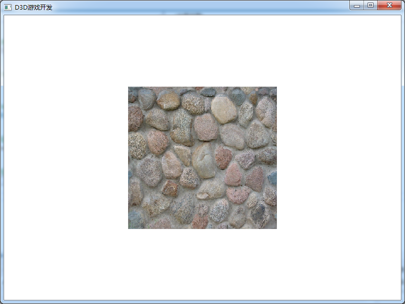
To sum up, the use of texture is actually very simple. It is to specify the texture coordinates of vertices, then load them into the texture object from a picture, and finally set the texture object for the graphics when rendering the graphics. Of course, this is only a use case of simple texture mapping. For some complex 3D models, its texture mapping is not specified in the code, but completed through the modeling software. For example, in 3ds max, you can use UV unfold or UV Map to perform UV mapping on complex models (human models). Therefore, when we load the 3D model file, the model already contains UV coordinate data. We only need to load the texture map file corresponding to the model, and then use the texture when rendering the model. This process is basically the same. The key of texture mapping is the correspondence between mapped UVs and model UVs. We can complete the simple code manually, and the complex one is completed by modeling software.
As we said before, the size of graphics drawn in DirectX is not a pixel unit. Due to the camera, the size displayed on the screen may be large or small. However, the size of our texture map is a fixed pixel size. For example, in this case, we use a 512 * 512 pixel JPG image. If the size of the quadrilateral on the screen is larger or smaller than the size of the texture map, some problems may occur. In most cases, the size of the graphics displayed on the screen and the size of the texture map are different. That is, the texture image may be enlarged or reduced. Multi texture rendering will cause multiple pixels on the screen to be mapped to the same texture element (texture elements are not enough), so that the rendering of 3D model will have the feeling of color block. Reducing the texture will cause the same pixel to be mapped to many texture elements (too many texture elements), so that the 3D model will be distorted or jagged. In order to solve the above problems, we need to fuse the colors of multiple texture elements into one pixel in different ways, which is called texture filtering. In Direct3D, there are four texture filtering methods: nearest point sampling filtering, linear texture filtering, anisotropic filtering and multi-level progressive filtering. Each filtering method has its own advantages and disadvantages. The SetSamplerState function is usually called to set the texture filtering method. The prototype of the function is as follows:
HRESULT SetSamplerState (
    DWORD Sampler,				// Specify the texture hierarchy, and the value is 0-7.
    D3DSAMPLERSTATETYPE Type,	// Texture sampling type
    DWORD Value					// Texture sampling parameter values
);
The nearest point sampling filter has the fastest speed but the worst effect. The code settings are as follows:
// Nearest point sampling
D3DDevice->SetSamplerState(0, D3DSAMP_MAGFILTER, D3DTEXF_POINT);
D3DDevice->SetSamplerState(0, D3DSAMP_MIPFILTER, D3DTEXF_POINT);
Linear texture filtering is the most widely used texture filtering method. Compared with the nearest point sampling method, it can effectively improve the image display quality, and has little impact on the system performance. It is to weighted average the target texture elements with the nearest four texture elements, up, down, left and right, so as to obtain the final displayed color value. The code is as follows:
// Linear texture
D3DDevice->SetSamplerState(0, D3DSAMP_MAGFILTER, D3DTEXF_LINEAR);
D3DDevice->SetSamplerState(0, D3DSAMP_MINFILTER, D3DTEXF_LINEAR);
Anisotropic texture filtering. This filtering method can get the best effect and consume a lot of calculation time. The code is set as follows:
// Anisotropic texture filtering
D3DDevice->SetSamplerState(0, D3DSAMP_MINFILTER, D3DTEXF_ANISOTROPIC);
D3DDevice->SetSamplerState(0, D3DSAMP_MIPFILTER, D3DTEXF_ANISOTROPIC);
D3DDevice->SetSamplerState(0, D3DSAMP_MAXANISOTROPY, 4);
In this case, we just use linear texture. This code can be placed below the texture object.
Multi level progressive filtering: to create a series of texture images with different sizes for textures. Multilevel progressive filtering is composed of a set of texture sequences with gradually reduced resolution. The size of each level of texture is half of that of the previous level. During texture mapping, Direct3D automatically selects a texture closest to the size of the object for mapping. Therefore, we usually create a texture with the highest resolution, and then use multi-level progressive filtering to generate multiple groups of textures. Multilevel progressive filtering can effectively improve the speed of graphics rendering. In fact, multi-level progressive filtering is also to solve the problem of texture map size.
Addressing mode: Direct3D can specify texture coordinates for vertices of any entity, and the value range of texture coordinates is [0,1]. However, in the actual process, this value range can not meet our requirements. Direct3D has four texture modes to handle situations beyond the range of [0,1]. They are repeat addressing mode, mirror texture addressing mode, clip texture addressing mode and border color texture addressing mode. Repeat addressing mode is the default addressing mode in Direct3D. This addressing mode allows the texture of the previous integer to be repeated at each integer link point. For example, if we draw a square and specify the texture coordinates of four vertices as (0,0), (0,2), (2,2), (2,0), Direct3D will assign the original texture twice in the U and V directions. That is, four sizes of original texture maps are displayed on the square. The mirror texture addressing mode automatically copies and flips the texture at each integer texture coordinate connection. The clip addressing mode extends the contents of the edge along the U and V axes. Border color texture addressing is that the part of fruit 1 is filled with border color.
Multi texture: it is to attach more than two texture maps to a model surface. The final pixel value of the pixels of the two texture maps is obtained according to a certain calculation formula and applied to the model vertices. The "lighting map" we talked about before is realized by this technology. The essence of multi texture is the formula calculation between pixels. We use VS2019 to create a new project "D3D_05_Multitexture" and copy the code of the previous project. This time, we prepare two texture maps, as follows:
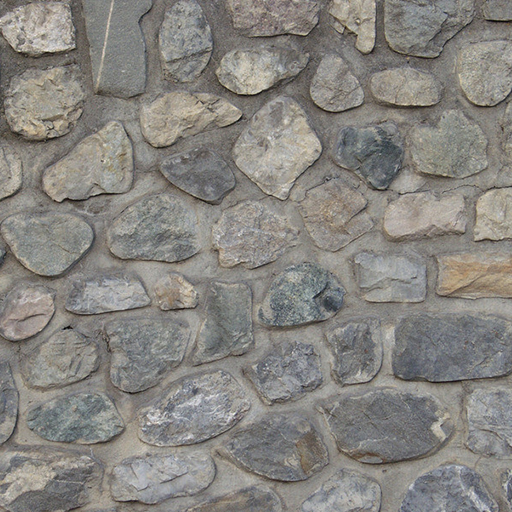
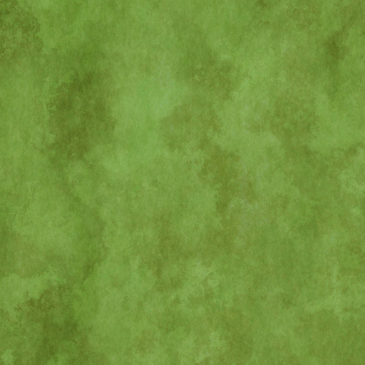
We will assign these two texture maps to a quadrilateral at the same time. First, we need to declare that the vertices of the quadrilateral support two UV coordinates, and then declare two texture objects. The code is as follows:
// Direct3D device pointer object
LPDIRECT3DDEVICE9 D3DDevice = NULL;

// Mouse position
int mx = 0, my = 0;

// Define FVF flexible vertex format structure
struct D3D_DATA_VERTEX { FLOAT x, y, z; DWORD color; FLOAT u1, v1, u2, v2; };

// Defines the vertex type that contains two textures
#define D3D_FVF_VERTEX (D3DFVF_XYZ | D3DFVF_DIFFUSE | D3DFVF_TEX1 | D3DFVF_TEX2)

// Vertex Buffer Objects
LPDIRECT3DVERTEXBUFFER9 D3DVertexBuffer = NULL;

// Two texture objects
LPDIRECT3DTEXTURE9 D3DTexture1 = NULL;
LPDIRECT3DTEXTURE9 D3DTexture2 = NULL;
Although we use two textures in vertices, because they are quadrilateral, their texture coordinates are actually the same. We readjust the vertex data of the quadrilateral in the initScene function. The vertex array data is as follows:
// Triangle V0V1V2, lower left corner clockwise
{ -10.0f, -10.0f, 0.0f, D3DCOLOR_XRGB(255,255,255), 0.0f, 1.0f, 0.0f, 1.0f },	// Lower left UV coordinates (0,1)
{ -10.0f,  10.0f, 0.0f, D3DCOLOR_XRGB(255,255,255), 0.0f, 0.0f, 0.0f, 0.0f },	// Upper left UV coordinates (0,0)
{  10.0f,  10.0f, 0.0f, D3DCOLOR_XRGB(255,255,255), 1.0f, 0.0f, 1.0f, 0.0f },	// Upper right UV coordinates (1,0)

// Triangle V0V2V3, lower left corner clockwise
{ -10.0f, -10.0f, 0.0f, D3DCOLOR_XRGB(255,255,255), 0.0f, 1.0f, 0.0f, 1.0f },	// Lower left UV coordinates (0,1)
{  10.0f,  10.0f, 0.0f, D3DCOLOR_XRGB(255,255,255), 1.0f, 0.0f, 1.0f, 0.0f },	// Upper right UV coordinates (1,0)
{  10.0f, -10.0f, 0.0f, D3DCOLOR_XRGB(255,255,255), 1.0f, 1.0f, 1.0f, 1.0f },	// UV coordinates in the lower right corner (1,1)
Although we have defined a certain color, it is only used to participate in the calculation of pixel formula. Finally, the color of quadrilateral is determined by two pictures. Then, we create two texture objects, that is, load the above two photos. The code is as follows:
// Create two texture objects
D3DXCreateTextureFromFile(D3DDevice, L"texture1.jpg", &D3DTexture1);
D3DXCreateTextureFromFile(D3DDevice, L"texture2.jpg", &D3DTexture2);
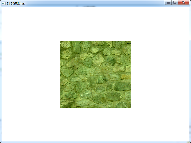
Next is our renderScene function. In this function, we need to calculate two texture objects. In this case, our calculation formula is multiplication, that is, multiply two pixels and assign them to a quadrilateral. Of course, we can also use addition. Different formulas get different visual effects. Here, we don't need to tangle with the implementation of the code. We mainly understand that the essence of multi texture is to obtain the final effect of mapped pixels according to a certain algorithm. The case code is as follows:
// Set the first texture to blend
D3DDevice->SetTextureStageState(0, D3DTSS_TEXCOORDINDEX, 0);
// The mixing formula is multiplication (addition)
D3DDevice->SetTextureStageState(0, D3DTSS_COLOROP, D3DTEXOPCAPS_MODULATE);
//D3DDevice->SetTextureStageState(0, D3DTSS_COLOROP, D3DTOP_ADD);
// Texture color multiplied by vertex color (result 1)
D3DDevice->SetTextureStageState(0, D3DTSS_COLORARG1, D3DTA_TEXTURE);
D3DDevice->SetTextureStageState(0, D3DTSS_COLORARG2, D3DTA_DIFFUSE);

// Set the second texture to blend
D3DDevice->SetTextureStageState(1, D3DTSS_TEXCOORDINDEX, 1);
// The mixing formula is multiplication (addition)
D3DDevice->SetTextureStageState(1, D3DTSS_COLOROP, D3DTEXOPCAPS_MODULATE);
//D3DDevice->SetTextureStageState(0, D3DTSS_COLOROP, D3DTOP_ADD);
// Multiplies the previous blend color (result 1) by the color of this texture
D3DDevice->SetTextureStageState(1, D3DTSS_COLORARG1, D3DTA_TEXTURE);
D3DDevice->SetTextureStageState(1, D3DTSS_COLORARG2, D3DTA_CURRENT);

// Set the texture and pay attention to the index
D3DDevice->SetTexture(0, D3DTexture1);
D3DDevice->SetTexture(1, D3DTexture2);

// Draw quadrilateral
D3DDevice->SetStreamSource(0, D3DVertexBuffer, 0, sizeof(D3D_DATA_VERTEX));
D3DDevice->SetFVF(D3D_FVF_VERTEX);
D3DDevice->DrawPrimitive(D3DPT_TRIANGLELIST, 0, 2);
At this point, the multi texture is completed. Run to view the effect, as follows:
Transparent texture pictures: the transparent pictures we use everyday are basically in PNG format. However, when a picture in this format is used as a texture map, the effect is not transparent. To display transparency in DirectX, you must require your texture map to include alpha channel. This channel stores the alpha value corresponding to each pixel in the image. Its value range is 0 - 255, which is a transition value from completely transparent (0) to opaque (255). Of course, 128 represents translucency. In fact, we can understand that the alpha channel is a gray image of the same size as the original image. Each pixel value on this gray image is the alpha value, that is, between 0-255. If you want part of the original image not to be displayed, the alpha value corresponding to this part should be 0, and the alpha channel is a black area.
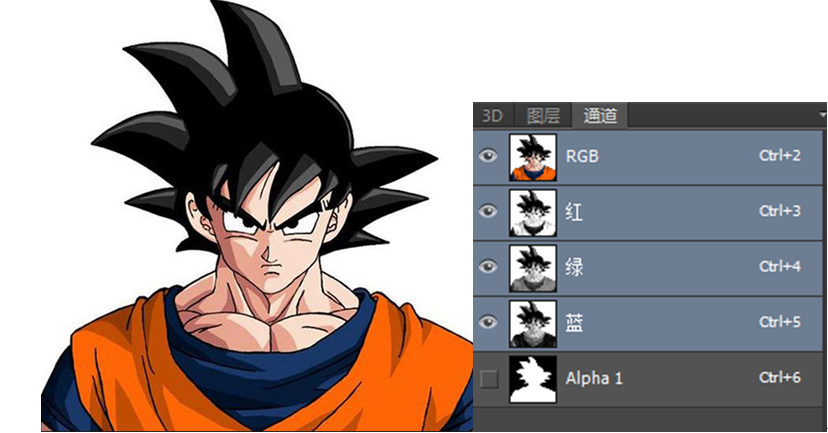
This is a texture map in BMP format, which can save the Alpha channel. We can see its Alpha channel in PS, which is actually a black-and-white image. We just want the colored areas to be displayed, and the blank differences should be completely transparent. That is, in the Alpha channel, those blank areas should correspond to black. We use VS2019 to create a new project "D3D_05_Transparent" and copy the previous project code of "D3D_05_Texture". Our code changes very little. First, the image name changes, so the creation of texture objects also needs to be adjusted,
// Create texture object
D3DXCreateTextureFromFile(D3DDevice, L"sunwukong.bmp", &D3DTexture);
Next is our renderScene function. In this function, we need to turn on Alpha fusion, and then set the source pixel, target pixel and operation mode, which are basically fixed. Finally, set the texture and paint. The code has given some comments, you can understand it.
// Turn on Alpha fusion
D3DDevice->SetRenderState(D3DRS_ALPHABLENDENABLE, true);

// Set blend factor
// The transparent object is the source pixel, so it uses its own alpha value
// An opaque object is the target pixel, so it uses the opposite alpha value of the source pixel, which is opaque
D3DDevice->SetRenderState(D3DRS_SRCBLEND, D3DBLEND_SRCALPHA);
D3DDevice->SetRenderState(D3DRS_DESTBLEND, D3DBLEND_INVSRCALPHA);

// Set fusion operation mode (addition)
D3DDevice->SetRenderState(D3DRS_BLENDOP, D3DBLENDOP_ADD);

// Set the texture and pay attention to the index
D3DDevice->SetTexture(0, D3DTexture);

// Draw quadrilateral
D3DDevice->SetStreamSource(0, D3DVertexBuffer, 0, sizeof(D3D_DATA_VERTEX));
D3DDevice->SetFVF(D3D_FVF_VERTEX);
D3DDevice->DrawPrimitive(D3DPT_TRIANGLELIST, 0, 2);

// Turn off Alpha blending
D3DDevice->SetRenderState(D3DRS_ALPHABLENDENABLE, false);
The operation effect is as follows:
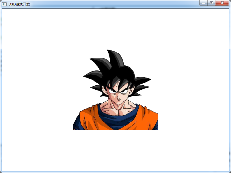
We can see that our transparent pictures are displayed correctly. It must be clear here that the PNG transparent pictures we use everyday are directly used as textures, and there is no transparent effect. We must use pictures with transparent channels, such as bmp format, tga format and so on. How to convert a transparent PNG format picture into a bmp format containing transparent channels will be introduced in the game art course, which will not be described in detail here.
How to make the model transparent, the other principle is to use texture transparency. Because we know that the model itself is just an empty shell. If the surface texture is transparent, the model will be transparent. We know that the color of the model comes from the diffuse reflection of the material. The alpha value of the diffuse reflection can be set in the material. Then, when rendering the model, turn on transparent fusion to achieve the transparent effect of the model. We have already talked about how to open transparent integration. How to set the diffuse alpha value of a material, the code is as follows:
// Set translucency!!!
D3DMaterials[i].Diffuse.a = alpha;
We will not introduce the specific code details here. The name of the project is "D3D_05_CubeTexture". In this project, we have respectively encapsulated the "Quad" quadrilateral class, the "Cube" cube class and the "Mesh" Mesh class, and how to use them in main.cpp. The grid code will be described in detail in Chapter 8. It should be noted that when using transparent blending, you must render opaque objects first, and then transparent objects.
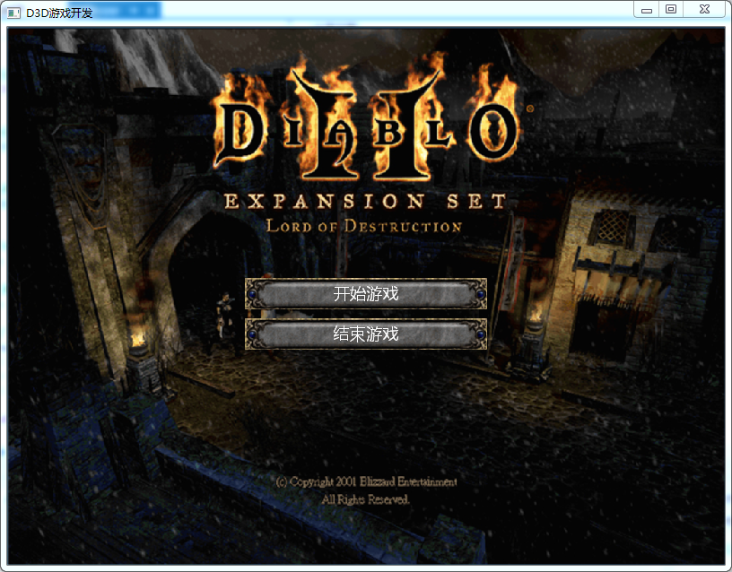
GUI: the user interface often used in game development, which is basically realized by using quadrilateral texture map. These user interfaces can respond to keyboard or mouse events, that is, interact with users. Next, we will complete a simple user interface, mainly one background and two buttons, and support user mouse click operation at the same time. When using quadrilateral to build user interface, we usually use D3DFVF_XYZRHW is a vertex type, that is, relative to the coordinate system of the form. The quadrilateral constructed in this way can be directly displayed on the form without projection transformation. We use VS2019 to create a new project "D3D_05_GUI" and copy the previous code. Starting from this case, we will gradually encapsulate various operations, that is, we will encapsulate the GUI into a simple class and then use it in main.cpp. In this way, in addition to creating the main.cpp main source code file, we should also create gui.h and gui.cpp files. At the same time, in order to make the introduction of header files public, we create the main.h file, which contains the following contents:
#pragma once
#include <windows.h>
#include <d3d9.h>
#include <d3dx9.h>

// Import dependent library files
#pragma comment(lib,"d3d9.lib")
#pragma comment(lib,"d3dx9.lib")

#define WINDOW_LEFT 		 two hundred 				//  window position
#define WINDOW_TOP 		 one hundred 				//  window position
#define WINDOW_WIDTH 	 eight hundred 				//  Window width
#define WINDOW_HEIGHT 	 six hundred 				//  Window height
#define WINDOW_TITLE 	 L"D3D game development" 	//  Window title
#define CLASS_NAME 		 L"D3D game development" 	//  Window class name
Next, let's look at the contents of the gui.h file:
#include "main.h"

// Define FVF flexible vertex format structure, using pixel coordinates
struct D3D_GUI_DATA_VERTEX { FLOAT x, y, z, rhw, u, v; };

// Defines the vertex type that contains the texture
#define D3D_GUI_FVF_VERTEX (D3DFVF_XYZRHW | D3DFVF_TEX1)

// Defining a GUI class is actually a quadrilateral texture
class Gui {

public:

	float posX, posY;		// GUI control location
	float width, height;		// GUI control size
	const wchar_t* txt;		// GUI control text
	const wchar_t* bg;		// GUI control background


	// GUI control texture object
	LPDIRECT3DTEXTURE9 texture = NULL;

	// GUI control vertex buffer object
	LPDIRECT3DVERTEXBUFFER9 buffer = NULL;

	// Font pointer object
	LPD3DXFONT D3DFont = NULL;

	// Direct3D device pointer object
	LPDIRECT3DDEVICE9 D3DDevice = NULL;

public:

	// Constructor
	Gui(LPDIRECT3DDEVICE9 device, LPD3DXFONT font, float x, float y, float w, float h, const wchar_t* t, const wchar_t* f);

	// Rendering function
	void render(RECT rect);

	// Destructor
	~Gui();

};
Our general idea is to complete the construction of quadrilateral vertex buffer object in the constructor, and then provide a render function to render quadrilateral and give texture map. The corresponding "gui.cpp" file is as follows:
#include "gui.h"

// Defining GUI classes: constructors
Gui::Gui(LPDIRECT3DDEVICE9 device, LPD3DXFONT font, float x, float y, float w, float h, const wchar_t* t, const wchar_t* f) {

	// Property assignment of class
	posX = x, posY = y;
	width = w, height = h;
	txt = t, bg = f;
	D3DFont = font;
	D3DDevice = device;

	// Calculate the four vertex coordinates of the quadrilateral according to the position and size
	float xLeft = posX;
	float xRight = posX + width;
	float yUp = posY;
	float yDown = posY + height;

	// Defines an array of quadrilateral vertices
	D3D_GUI_DATA_VERTEX vertexArray[] =
	{
		{ xLeft,  yDown, 0.0f, 1.0f, 0.0f, 1.0f },
		{ xLeft,  yUp,   0.0f, 1.0f, 0.0f, 0.0f },
		{ xRight, yUp,	 0.0f, 1.0f, 1.0f, 0.0f },
		{ xLeft,  yDown, 0.0f, 1.0f, 0.0f, 1.0f },
		{ xRight, yUp,   0.0f, 1.0f, 1.0f, 0.0f },
		{ xRight, yDown, 0.0f, 1.0f, 1.0f, 1.0f },
	};

	// Create vertex buffer object
	D3DDevice->CreateVertexBuffer(sizeof(vertexArray), 0, D3D_GUI_FVF_VERTEX, D3DPOOL_DEFAULT, &buffer, NULL);

	// Fill vertex buffer object
	void* ptr;
	buffer->Lock(0, sizeof(vertexArray), (void**)&ptr, 0);
	memcpy(ptr, vertexArray, sizeof(vertexArray));
	buffer->Unlock();

	// Create texture object
	//D3DXCreateTextureFromFile(D3DDevice, bg, &texture);
	D3DXCreateTextureFromFileEx(
		D3DDevice,					// Call in is an IDirect3DDevice9 object pointer
		bg,							// file name
		D3DX_DEFAULT,				// Width of image, default D3DX_DEFAULT is OK
		D3DX_DEFAULT,				// Length of image, default D3DX_DEFAULT is OK
		D3DX_DEFAULT,				// Picture layer, default D3DX_DEFAULT is OK
		0,							// Set the usage of this texture. This parameter can be 0,
		D3DFMT_UNKNOWN,			// Texture format, using D3DFMT_UNKNOWN
		D3DPOOL_MANAGED,			// D3dpool is generally used_ MANAGED
		D3DX_FILTER_TRIANGLE,		// Image pixel filtering method, D3DX_FILTER_TRIANGLE
		D3DX_FILTER_TRIANGLE,		// MIP pixel filtering method, D3DX_FILTER_TRIANGLE
		D3DCOLOR_RGBA(0, 0, 0, 255),	// Transparent color, d3dcolor_ RGBA (0,0,0255)
		NULL,						// Record the loaded picture information, and use NULL
		NULL,						// Record palette information and use NULL
		&texture);						// Used to store instances of texture objects loaded with pictures
};


// Defining GUI classes: rendering functions
void Gui::render(RECT rect) {

	// Set texture
	D3DDevice->SetTexture(0, texture);

	// Draw quadrilateral
	D3DDevice->SetStreamSource(0, buffer, 0, sizeof(D3D_GUI_DATA_VERTEX));
	D3DDevice->SetFVF(D3D_GUI_FVF_VERTEX);
	D3DDevice->DrawPrimitive(D3DPT_TRIANGLELIST, 0, 2);

	// Draw text
	if (wcslen(txt) > 0) {

		rect.top = posY + 5;
		D3DFont->DrawText(
			0,								// Pointer to id3dxssprite object
			txt,								// Points to the string to draw
			-1,								// The number of characters in the string
			&rect,							// RECT text drawing rectangle
			DT_CENTER,						// Text alignment format
			D3DCOLOR_XRGB(255, 255, 255));		// The color of the text
	}
};

// Defining GUI classes: destructors
Gui::~Gui() {

	buffer->Release();
	buffer = NULL;
	texture->Release();
	texture = NULL;
};
The code is basically what we have learned. When creating texture objects, we use D3DXCreateTextureFromFileEx to load a picture that is not square. In fact, there is no big problem using D3DXCreateTextureFromFile. This problem is no longer discussed in depth. After completing the encapsulation of Gui, we will start the of the main source file main.cpp. First, the declaration of global variables:
// Import header file
#include "main.h"
#include "gui.h"


// Direct3D device pointer object
LPDIRECT3DDEVICE9 D3DDevice = NULL;

// Mouse position
int mx = 0, my = 0;

// Font pointer object
LPD3DXFONT D3DFont = NULL;

// Define GUI control array
Gui* bg, * btn1, * btn2;
Because we have encapsulated it, we only need to define three classes through Gui. Next is the initScene function, which is as follows:
// Create font object
D3DXCreateFont(
	D3DDevice,				// DirectX device object
	24,						// The height of the font, in logical units
	0,						// The width of the font, in logical units
	1,						// Font weight, bold
	1,						// Text Mipmap level
	false,						// Whether the text is tilted
	DEFAULT_CHARSET,		// character set
	OUT_DEFAULT_PRECIS,	// Specifies that Windows attempts to match the required font size and characteristics to the actual font
	DEFAULT_QUALITY,		// The specified Windows font matches the actual font
	0,						// pitch and family index
	L"Microsoft YaHei ",				// Font type
	&D3DFont);				// Font object

	// Initialization background
	bg = new Gui(D3DDevice, D3DFont, 0, 0, 800, 600, L"", L"bg.jpg");

	// Initialization button 1
	btn1 = new Gui(D3DDevice, D3DFont, 265, 280, 270, 35, L"Start the game", L"btn.jpg");

	// Initialization button 2
	btn2 = new Gui(D3DDevice, D3DFont, 265, 325, 270, 35, L"End the game", L"btn.jpg");
The general parameters for creating font objects are also annotated. You can understand some. Because we do not need projection and illumination, we have removed the initProjection function and initLight function. Next is the renderScene function. The code is as follows:
// Define a rectangle (window size)
RECT rect = { 0, 0, WINDOW_WIDTH , WINDOW_HEIGHT };

// Render three GUI s
bg->render(rect);
btn1->render(rect);
btn2->render(rect);
After my encapsulation, the use of Gui is very simple. Run the program, and the effect is as follows:
Finally, let's introduce how to judge the mouse click event, that is, our update method:
// Mouse click event
if (type != 3) return;

// Do you want to click the start game button
if (mx > btn1->posX && mx < btn1->posX + btn1->width && my > btn1->posY && my < btn1->posY + btn1->height) {
	MessageBox(NULL, L"Start the game", L"Tips", 0);
}

// Do you want to click the end game button
if (mx > btn2->posX && mx < btn2->posX + btn2->width && my > btn2->posY && my < btn2->posY + btn2->height) {
MessageBox(NULL, L"End the game", L"Tips", 0);
}
In fact, this algorithm is very simple. It is to judge whether the position of the mouse falls in the area of the button quadrilateral. After running, click the button and a prompt box will be displayed. The last key point is the size of the window and the size of the customer area. Although we set the size of the form to 800 * 600, the area we really use (client area) is not so large. Because every Windows form has a title and border. Therefore, in order to accurately judge the mouse position, we need to adjust our customer area to 800 * 600. In this way, the actual size of our form will be greater than 800 * 600.
When we call the CreateWindowEx() function, we use 800 and 600 to set the size of the window, respectively. However, the window size is different from the size of the client area, which refers to the part of the window that does not contain a boundary. The window size is calculated from the outside of the border, while the client size is calculated from the inside of the border. When rendering, we will only draw on the client area of the window, so it is very important to understand the size of the client area. When drawing with D3D, we need to specify the size of the image to be generated. If the size of the client area does not match the size of the image, the image will be stretched or compressed to adapt to the size of the client area. Rather than setting the window size first and then determining the client size, it is better to determine the client size first and then determine the appropriate window size. To do this, we need to use the AdjustWindowRect() function before creating the window. The function of this function is very simple. What it does is to obtain the size and position of the client area, and then calculate the size and position of the necessary window.
// Specifies that the size of the client area is windows_ Width and WINDOW_HEIGHT
// Then recalculate the window size w and h
RECT clientSize = { 0, 0, WINDOW_WIDTH, WINDOW_HEIGHT };
AdjustWindowRect(&clientSize, WS_OVERLAPPEDWINDOW, FALSE);
int w = clientSize.right - clientSize.left;
int h = clientSize.bottom - clientSize.top;
Then use the new w and h in our CreateWindow and MoveWindow methods.
Download address of all code cases of this course:
Note: This is the second course in our game development series. This course mainly uses C + + language and DirectX to explain some basic theoretical knowledge in game development. The learning goal is mainly based on understanding theoretical knowledge. The attached C + + code can be understood and run successfully. We are not required to use DirectX to develop games. If there are some mistakes in the course, please leave a message and correct them. Thank you very much!