I. Preface
In the APU system, the CPU performs the operation in the way of serial code execution, and the software mode is difficult to achieve accurate timing, so it is a better choice to call the internal timer hardware to complete timing. In this paper, timer interrupt control LED periodic flicker as an example to learn the use of private timer. At the same time, learn how to solidify the software program and the hardware bitstream file into the SD card, and realize the power on automatic configuration and start the custom system.
Function definition: the level of single LED connected with MIO changes in turn every 200ms through timer interruption, that is, it is on, it is off after 200ms, it is on again after 200ms, and the cycle is reciprocating.
Hardware platform: milianz702n
Software tool: VIVADO 2017.4+SDK
2, Hardware system construction
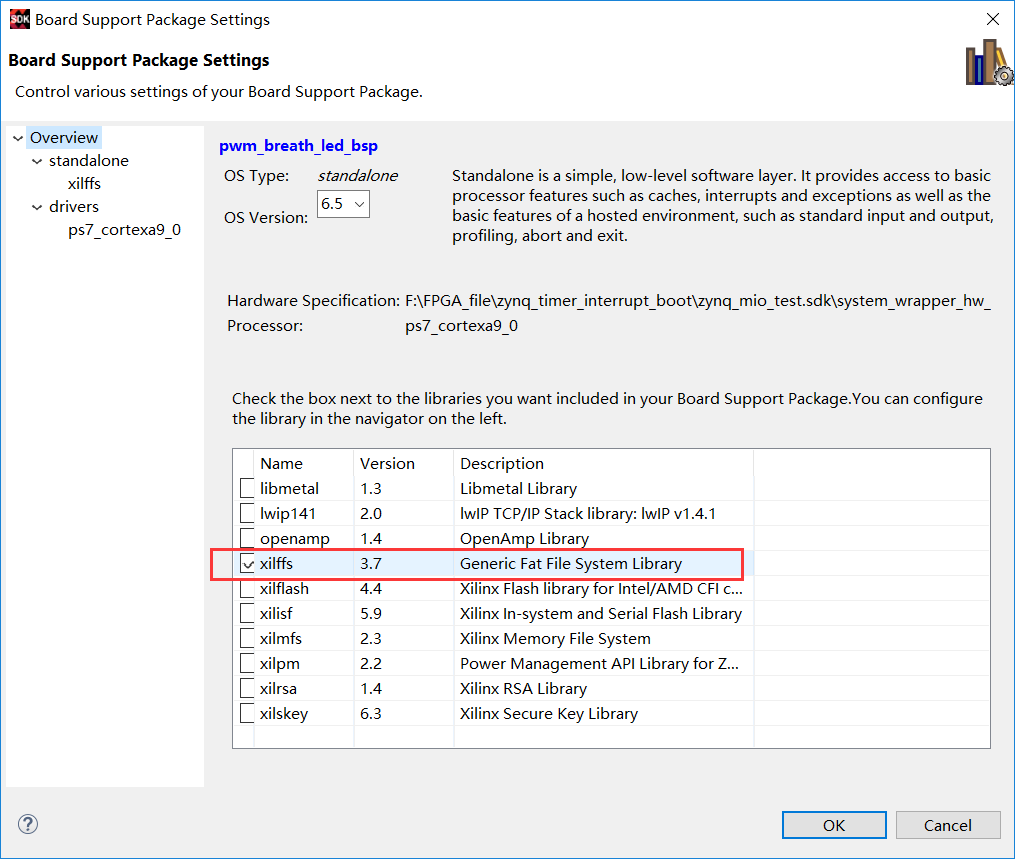
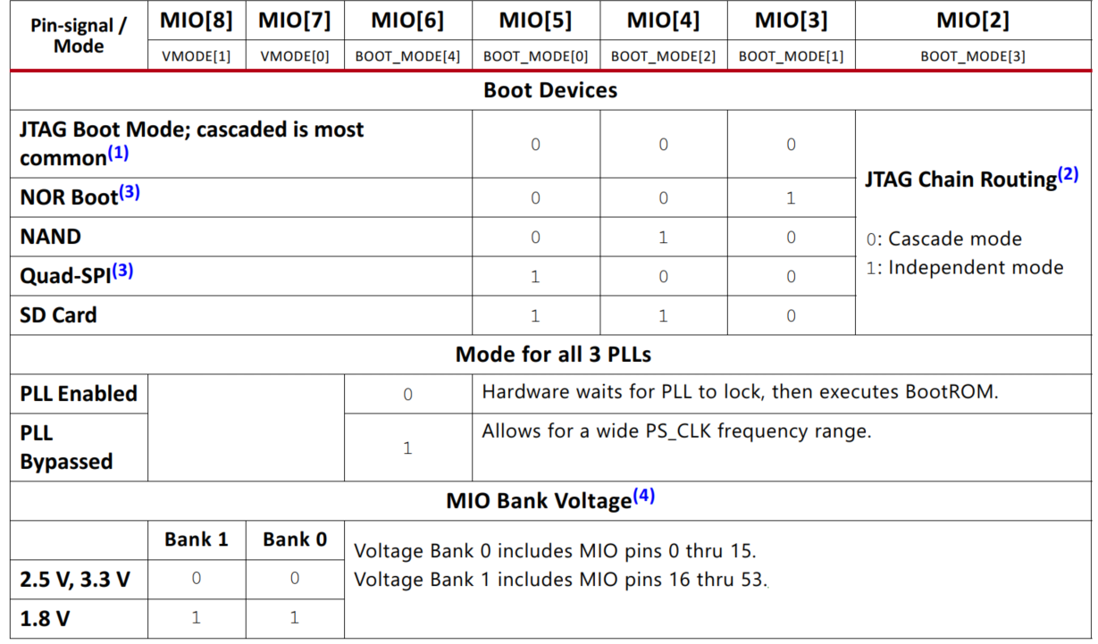
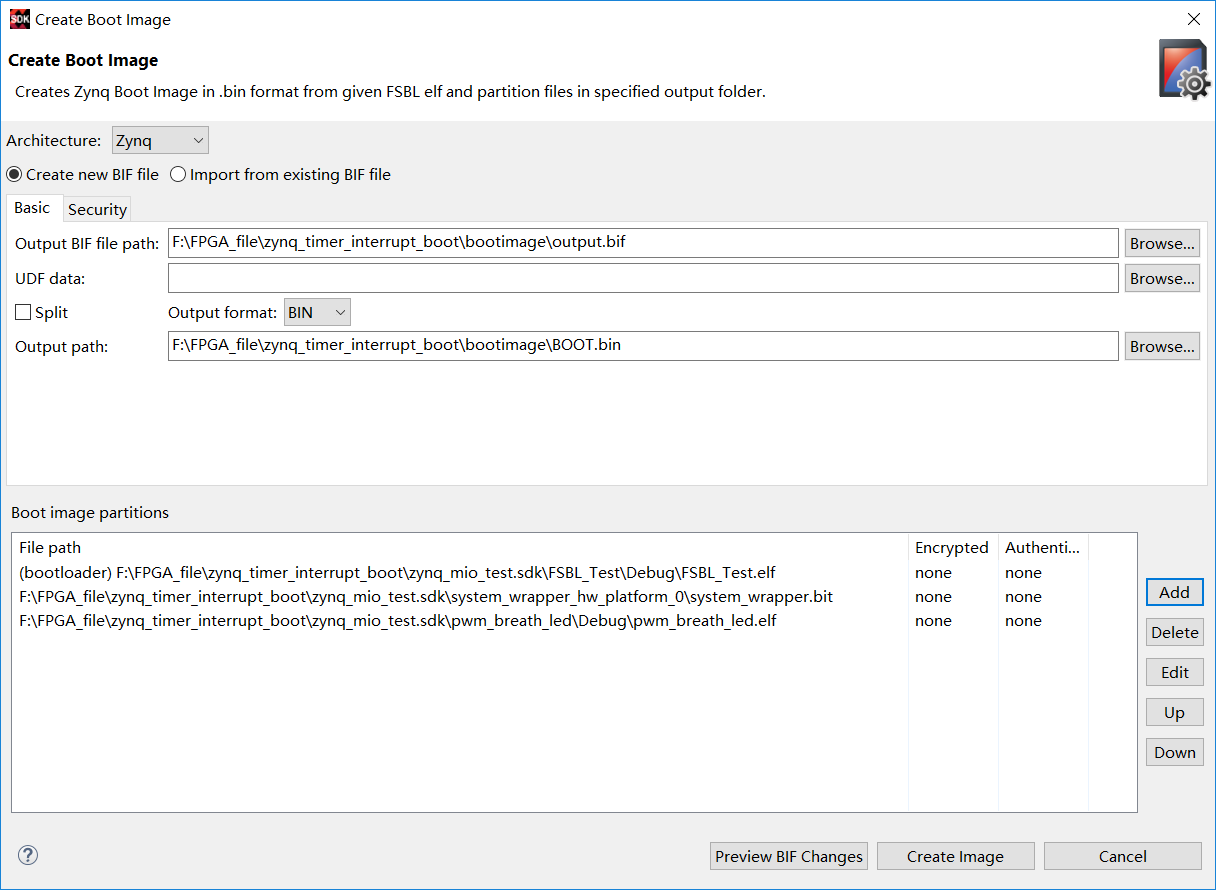
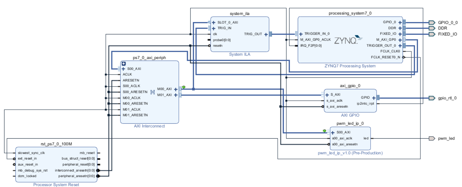
The private timer belongs to the special hardware resource in APU, and does not need to be configured in VIVADO. Due to the need to solidify the hardware and software system into the SD card, I/O connected to the SD controller is selected.
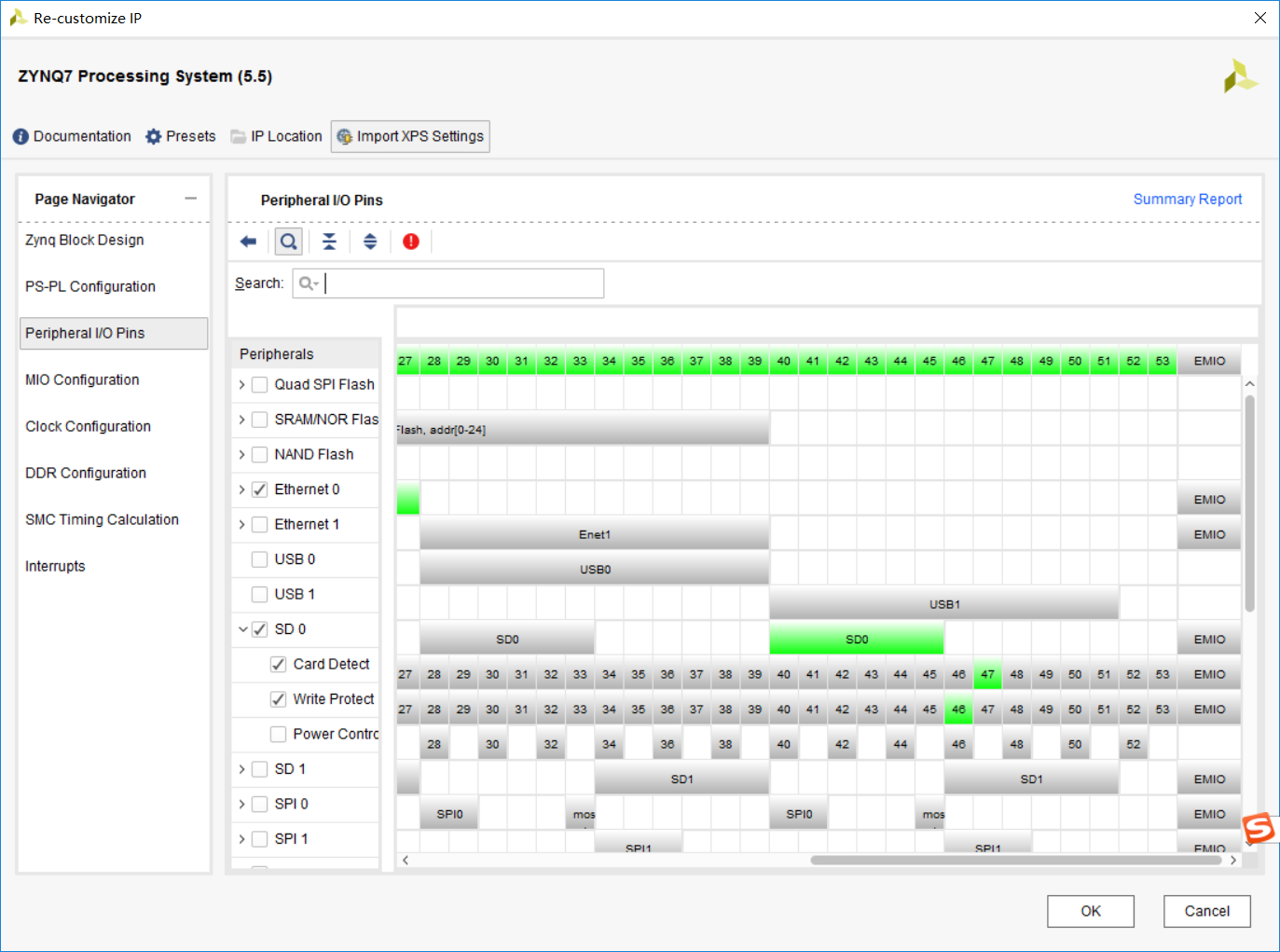
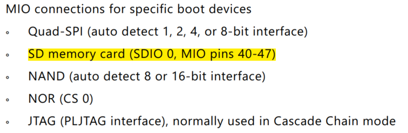
According to the schematic diagram, SD card is connected in mio40-47, which is also consistent with the description in UG585:
In this paper, we use PWM directly to produce the hardware system of the respiratory lamp effect engineering. We can more intuitively observe that the timer control LED and PWM control LED do not affect each other.
It is still to regenerate output files, generate HDL Wrapper, RUN Synthesis, Run Implementation, Generate bitstream, export Hardware with bitfile, Launch SDK. The rest of the tasks are completed in the SDK.
Three, software design
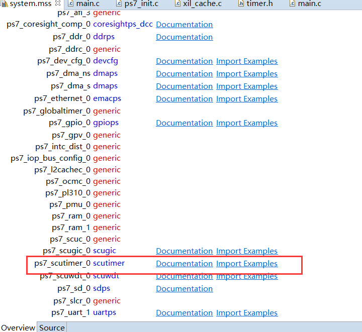
xilinx also provides documentation and sample programs on how to use private timers.
The timer related functions used in the software code are all from the sample program. The first step of using the private timer is to initialize the configuration of course. The old routine calls two functions, xscutimer? Lookupconfig and xscutimer? Cfginitialize. In order to ensure the periodic flashing of LED, it is necessary to enable the automatic overload of timer, so that the counter will be re counted every time the counter counting is completed. The most important thing is to write the count cycle value to the timer load register. In fact, the private timer is a decrement counter. When the maximum value is decremented to 0, timer interrupt will occur. For example, and convert the time length to be timed to the cycle value of the load counter?
Simply, n=t/T=t*f can calculate the loading value, where N, t and t refer to the time to be timed and the working clock period of the timer respectively. Because the working clock frequency of timer is always half of that of CPU, which is 333MHz in this system. This n = 200 * 10 ^ (- 3 * 333 * 10 ^ 6 = 666 * 10 ^ 5. The counter is a counting mode of N-1~0, and the loading value is minus 1 on the basis of N, and the corresponding hex value is 0x3F83C3F.
When the load is completed, the XScuTimer_Start timer is invoked. Finally, in the timer interrupt callback function, the MIO can be reversed to meet the functional expectations. In addition, some improvements have been made to the project of realizing the effect of breathing lamp by PWM. The software program is as follows:
main.c 1 /* 2 * main.c 3 * 4 * Created on: 2020 February 22nd 2013 5 * Author: s 6 */ 7 8 9 #include "environment.h" 10 11 12 13 int main() 14 { 15 int Status; 16 u8 i=0; 17 18 freq_step_value = 10; 19 20 Status = gpiops_initialize(&GpioPs,GPIOPS_DEVICE_ID); 21 if (Status != XST_SUCCESS) { 22 return XST_FAILURE; 23 } 24 25 Status = gpio_initialize(&Gpio,GPIO_DEVICE_ID); 26 if (Status != XST_SUCCESS) { 27 return XST_FAILURE; 28 } 29 30 Status = timer_initialize(&TimerInstance,TIMER_DEVICE_ID); 31 if (Status != XST_SUCCESS) { 32 return XST_FAILURE; 33 } 34 /* 35 * Set the direction for the pin to be output and 36 * Enable the Output enable for the LED Pin. 37 */ 38 gpiops_setOutput(&GpioPs,MIO_OUT_PIN_INDEX); 39 40 for(i=0;i<LOOP_NUM;i++){ 41 gpiops_setOutput(&GpioPs,EMIO_OUT_PIN_BASE_INDEX+i); 42 } 43 44 gpio_setDirect(&Gpio, 1,GPIO_CHANNEL1); 45 46 Status = setupIntSystem(&Intc,&Gpio,&TimerInstance, 47 INTC_GPIO_INTERRUPT_ID,TIMER_IRPT_INTR); 48 if (Status != XST_SUCCESS) { 49 return XST_FAILURE; 50 } 51 52 /* 53 * Enable Auto reload mode. 54 */ 55 XScuTimer_EnableAutoReload(&TimerInstance); 56 57 /* 58 * Load the timer counter register. 59 */ 60 XScuTimer_LoadTimer(&TimerInstance, TIMER_LOAD_VALUE); 61 62 /* 63 * Start the timer counter and then wait for it 64 * to timeout a number of times. 65 */ 66 XScuTimer_Start(&TimerInstance); 67 68 69 70 Status = pwm_led_setFreqStep(freq_step_value); 71 if (Status != XST_SUCCESS) { 72 return XST_FAILURE; 73 } 74 75 printf("Initialization finish.\n"); 76 77 while(1){ 78 79 for(i=0;i<LOOP_NUM;i++){ 80 if(int_flag == 0) 81 { 82 gpiops_outputValue(&GpioPs, EMIO_OUT_PIN_BASE_INDEX+i, 0x1); 83 usleep(200*1000); 84 gpiops_outputValue(&GpioPs, EMIO_OUT_PIN_BASE_INDEX+i, 0x0); 85 } 86 else 87 { 88 gpiops_outputValue(&GpioPs, EMIO_OUT_PIN_BASE_INDEX+LOOP_NUM-1-i, 0x1); 89 usleep(200*1000); 90 gpiops_outputValue(&GpioPs, EMIO_OUT_PIN_BASE_INDEX+LOOP_NUM-1-i, 0x0); 91 } 92 } 93 94 95 } 96 return 0; 97 } 98 99 100 101 int setupIntSystem(XScuGic *IntcInstancePtr,XGpio *gpioInstancePtr, 102 XScuTimer * TimerInstancePtr,u32 gpio_IntrId,u32 timer_IntrId) 103 { 104 int Result; 105 /* 106 * Initialize the interrupt controller driver so that it is ready to 107 * use. 108 */ 109 110 Result = gic_initialize(&Intc,INTC_DEVICE_ID); 111 if (Result != XST_SUCCESS) { 112 return XST_FAILURE; 113 } 114 115 XScuGic_SetPriorityTriggerType(IntcInstancePtr, gpio_IntrId, 116 0xA0, 0x3); 117 118 /* 119 * Connect the interrupt handler that will be called when an 120 * interrupt occurs for the device. 121 */ 122 Result = XScuGic_Connect(IntcInstancePtr, gpio_IntrId, 123 (Xil_ExceptionHandler)GpioHandler, gpioInstancePtr); 124 if (Result != XST_SUCCESS) { 125 return Result; 126 } 127 128 Result = XScuGic_Connect(IntcInstancePtr, timer_IntrId, 129 (Xil_ExceptionHandler)TimerIntrHandler, 130 (void *)TimerInstancePtr); 131 if (Result != XST_SUCCESS) { 132 return Result; 133 } 134 135 /* Enable the interrupt for the GPIO device.*/ 136 XScuGic_Enable(IntcInstancePtr, gpio_IntrId); 137 138 /* 139 * Enable the GPIO channel interrupts so that push button can be 140 * detected and enable interrupts for the GPIO device 141 */ 142 XGpio_InterruptEnable(gpioInstancePtr,GPIO_CHANNEL1); 143 XGpio_InterruptGlobalEnable(gpioInstancePtr); 144 145 /* 146 * Enable the interrupt for the device. 147 */ 148 XScuGic_Enable(IntcInstancePtr, timer_IntrId); 149 XScuTimer_EnableInterrupt(TimerInstancePtr); 150 151 /* 152 * Initialize the exception table and register the interrupt 153 * controller handler with the exception table 154 */ 155 exception_enable(&Intc); 156 157 IntrFlag = 0; 158 159 return XST_SUCCESS; 160 } 161 162 void GpioHandler(void *CallbackRef) 163 { 164 XGpio *GpioPtr = (XGpio *)CallbackRef; 165 u32 gpio_inputValue; 166 167 168 /* Clear the Interrupt */ 169 XGpio_InterruptClear(GpioPtr, GPIO_CHANNEL1); 170 printf("gpio interrupt.\n"); 171 172 //IntrFlag = 1; 173 gpio_inputValue = gpio_readValue(GpioPtr, 1); 174 switch(gpio_inputValue) 175 { 176 case 30: 177 //printf("button up\n"); 178 usleep(5); 179 gpio_inputValue = gpio_readValue(GpioPtr, 1); 180 if(gpio_inputValue == 30){ 181 freq_step_value = freq_step_value < FREQ_STEP_MAX ? 182 freq_step_value+10 : freq_step_value; 183 printf("%d\n",freq_step_value); 184 pwm_led_setFreqStep(freq_step_value); 185 } 186 break; 187 case 29: 188 //printf("button center\n"); 189 usleep(5); 190 gpio_inputValue = gpio_readValue(GpioPtr, 1); 191 if(gpio_inputValue == 29){ 192 freq_step_value = FREQ_STEP_SET_VALUE; 193 pwm_led_setFreqStep(freq_step_value); 194 } 195 break; 196 case 27: 197 //printf("button left\n"); 198 usleep(5); 199 gpio_inputValue = gpio_readValue(GpioPtr, 1); 200 if(gpio_inputValue == 27) 201 int_flag = 0; 202 break; 203 case 23: 204 //printf("button right\n"); 205 usleep(5); 206 gpio_inputValue = gpio_readValue(GpioPtr, 1); 207 if(gpio_inputValue == 23) 208 int_flag = 1; 209 break; 210 case 15: 211 //print("button down\n"); 212 usleep(5); 213 gpio_inputValue = gpio_readValue(GpioPtr, 1); 214 if(gpio_inputValue == 15){ 215 freq_step_value = freq_step_value > FREQ_STEP_MIN ? 216 freq_step_value-10 : freq_step_value; 217 printf("%d\n",freq_step_value); 218 pwm_led_setFreqStep(freq_step_value); 219 } 220 break; 221 } 222 223 } 224 225 void TimerIntrHandler(void *CallBackRef) 226 { 227 XScuTimer *TimerInstancePtr = (XScuTimer *) CallBackRef; 228 229 XScuTimer_ClearInterruptStatus(TimerInstancePtr); 230 231 gpiops_outputValue(&GpioPs, MIO_OUT_PIN_INDEX, sys_led_out); 232 sys_led_out = sys_led_out == 0x0 ? 0x1 : 0x0; 233 }