External interrupt
External hardware interrupt
For the interrupt signal from the outside of the processor, the external hardware interrupt is introduced into the processor through two signal lines, and the signal lines of 8086 processor are NMI and INTR
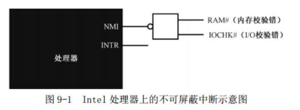
- Non masked interrupt (NMI) is an interrupt that will not be blocked or masked. intel processor stipulates that NMI interrupt signal must be maintained for more than 4 clock cycles after jumping from 0 to 1. The interrupt number of NMI in real mode is 2
- It can mask interrupts. intel processor allows 256 interrupts, and 8259 chip (interrupt controller) provides 15 of them
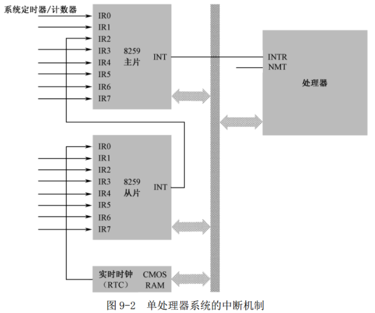
There is an interrupt mask register IMR in the 8259, which corresponds to 8 pins, which determines that this pin can transmit the interrupt signal to the processor. Whether the interrupt can be processed depends on the IF bit of the flag register, which is set through cli and sti
Interrupt vector table (real mode)
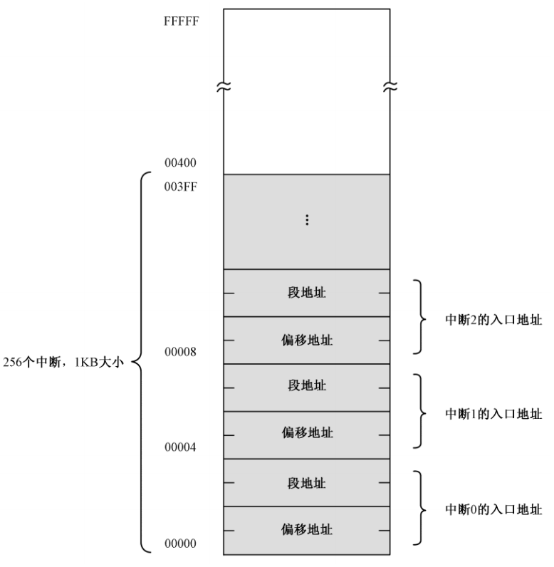
In real mode, the entry point of the interrupt handler is 0x00000 to 0x003ff of the physical address of the memory, with a total space of 1KB, that is, the interrupt vector table
Each interrupt occupies a double word in the interrupt vector table
Process for handling interrupts:
- Protect the breakpoint site, stack the flag register FLAGS, clear IF (interrupt flag) and TF (trap flag), and stack CS and IP
- Execute the interrupt program, multiply the obtained terminal number by 4 in the interrupt vector table, take out the offset address and segment address of the interrupt program, and transmit CS and IP. At this time, because the IF flag is cleared, the processor will no longer respond to the interrupt during interrupt processing
- Return to the breakpoint to continue execution. The last instruction of the interrupt handler is iret. The processor successively exits the stack CS and IP and marks the register area
Interrupts can occur at any time, so the interrupt vector table is completed by BIOS when the computer starts
Real time clock
In the peripheral device control chip ICH, real-time clock circuit RTC and static memory CMOS RAM are integrated
The date and time information is stored in CMOS RAM, usually 128 bytes, while the date and time information only accounts for a small part of the capacity. Other space is used to save the configuration information of the whole machine, such as the type and working parameters of various hardware, startup password and startup sequence of auxiliary storage devices.
The RTC chip is driven by a quartz crystal oscillator (crystal oscillator) with an oscillation frequency of 32.768kHz. After frequency division, it is used to refresh the CMOS RAM once per second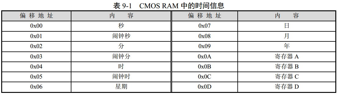
CMOS RAM needs to be accessed through two ports. 0x70 or 0x74 is the index port, which is used to specify the unit in CMOS RAM; 0x71 or 0x75 is the data port used to read and write the contents of the corresponding unit
;Read week
mov al,0x06
out 0x70,al
in al,ox71
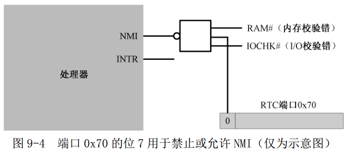
From a very early time, the highest bit (bit 7) of port 0x70 is the switch that controls NMI interrupt. When it is 0, NMI interrupt is allowed to reach the processor. When it is 1, all NMI signals are blocked. The other 7 bits, i.e. 0 ~ 6 bits,
It is actually used to specify the index number of CMOS RAM unit. Although bit 7 of port 0x70 is not an interrupt signal, it can control the output of NAND gate and determine whether the real NMI interrupt signal can reach the processor.
In the early system, the manufacturing cost of computer was very high. In order to maximize the use of hardware resources, this strange practice was caused,
The date and time saved in CMOS RAM are usually Binary Coded Decimal (BCD)
Units 0x0A ~ 0x0D are not ordinary storage units, but are defined as index numbers of four registers, which are also accessed through ports 0x70 and 0x71. These four registers are used to set the parameters and working status of the real-time clock circuit
Registers A and B are used to set the functions of RTC as A whole. Refer to P156 for details
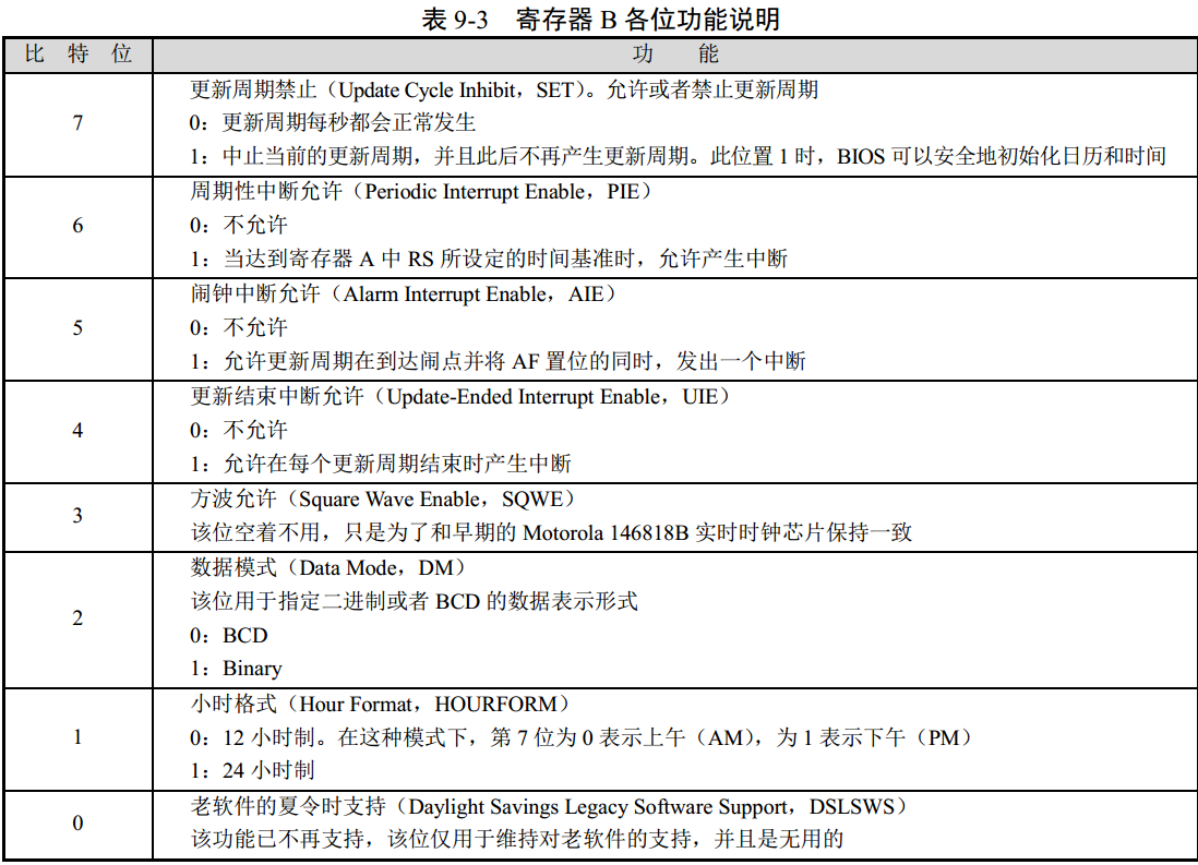
Each time an interrupt actually occurs, the contents of register C can be read in the program (interrupt processing process) to check the cause of the interrupt. Another feature of this register is that every time it is read, all contents are automatically cleared. Moreover, if it is not read (in other words, the corresponding bit is not cleared), the same interrupt will no longer be generated.
Program objective: RTC chip sends interrupt regularly, executes code and reads CMOS RAM information
User program
Note: when the processor is designed, it is specified that when an instruction modifying the segment register SS is encountered, interrupt is prohibited during the execution of this instruction and the next instruction, so as to protect the stack
After the computer starts, the interrupt number of RTC chip is 0x70 by default
         ;Code listing 9-1
         ;File name: c09_1.asm
         ;File Description: user program
         ;Date of creation: 2011-4-16 22:03

;===============================================================================
SECTION header vstart=0                     ;Define user program header segment
    program_length  dd program_end          ;Total program length[0x00]

    ;User program entry point
    code_entry      dw start                ;Offset address[0x04]
                    dd section.code.start   ;Segment address[0x06]

    realloc_tbl_len dw (header_end-realloc_begin)/4
                                            ;Number of segment relocation table entries[0x0a]

    realloc_begin:
    ;Segment relocation table
    code_segment    dd section.code.start   ;[0x0c]
    data_segment    dd section.data.start   ;[0x14]
    stack_segment   dd section.stack.start  ;[0x1c]

header_end:

;===============================================================================
SECTION code align=16 vstart=0           ;Define code snippets (16 byte alignment)
new_int_0x70:
      push ax
      push bx
      push cx
      push dx
      push es

  .w0:
      mov al,0x0a                        ;block NMI. Of course, it is usually unnecessary
      or al,0x80
      out 0x70,al
      in al,0x71                         ;Read register A
      test al,0x80                       ;Test bit 7 UIP
      jnz .w0                            ;The above code is for the end of the update cycle interrupt
                                         ;be not necessary
      xor al,al
      or al,0x80
      out 0x70,al
      in al,0x71                         ;read RTC current time (second)
      push ax

      mov al,2
      or al,0x80
      out 0x70,al
      in al,0x71                         ;read RTC current time (branch)
      push ax

      mov al,4
      or al,0x80
      out 0x70,al
      in al,0x71                         ;read RTC current time (Time)
      push ax

      mov al,0x0c                        ;register C Index of. And open NMI
      out 0x70,al
      in al,0x71                         ;Read it RTC Register of C,Otherwise, only one interrupt occurs
                                         ;Alarms and periodic interruptions are not considered here
      mov ax,0xb800
      mov es,ax

      pop ax
      call bcd_to_ascii
      mov bx,12*160 + 36*2               ;Start with 12 rows and 36 columns on the screen

      mov [es:bx],ah
      mov [es:bx+2],al                   ;Display two hour numbers

      mov al,':'
      mov [es:bx+4],al                   ;Display separator':'
      not byte [es:bx+5]                 ;Reverse display properties

      pop ax
      call bcd_to_ascii
      mov [es:bx+6],ah
      mov [es:bx+8],al                   ;Displays a two digit minute number

      mov al,':'
      mov [es:bx+10],al                  ;Display separator':'
      not byte [es:bx+11]                ;Reverse display properties

      pop ax
      call bcd_to_ascii
      mov [es:bx+12],ah
      mov [es:bx+14],al                  ;Display two hour numbers

      mov al,0x20                        ;Interrupt end command EOI
      out 0xa0,al                        ;Send to slave
      out 0x20,al                        ;Send to master

      pop es
      pop dx
      pop cx
      pop bx
      pop ax

      iret

;-------------------------------------------------------------------------------
bcd_to_ascii:                            ;BCD Code conversion ASCII
                                         ;Input: AL=bcd code
                                         ;Output: AX=ascii
      mov ah,al                          ;Split into two numbers
      and al,0x0f                        ;Only the lower 4 bits are reserved
      add al,0x30                        ;convert to ASCII

      shr ah,4                           ;Logical shift right 4 bits
      and ah,0x0f
      add ah,0x30

      ret

;-------------------------------------------------------------------------------
start:
      mov ax,[stack_segment]
      mov ss,ax
      mov sp,ss_pointer
      mov ax,[data_segment]
      mov ds,ax

      mov bx,init_msg                    ;Display initial information
      call put_string

      mov bx,inst_msg                    ;Display installation information
      call put_string

      mov al,0x70
      mov bl,4
      mul bl                             ;Calculate 0 x70 No. interrupt at IVT Offset in
      mov bx,ax

      cli                                ;Prevent new 0 during changes x70 No. interrupt

      push es
      mov ax,0x0000
      mov es,ax
      mov word [es:bx],new_int_0x70      ;Offset address.
                                          ;Write the address of the interrupt handler to the interrupt vector table
      mov word [es:bx+2],cs              ;Segment address
      pop es

      mov al,0x0b                        ;RTC register B
      or al,0x80                         ;block NMI
      out 0x70,al
      mov al,0x12                        ;Set register B,Periodic interruption is prohibited and more open
      out 0x71,al                        ;Interrupt after new, BCD Yard, 24-hour system

      mov al,0x0c
      out 0x70,al
      in al,0x71                         ;read RTC register C,Reset pending interrupt status

;RTC After the chip is set, the 8259 will not be allowed RTC Interrupt, you need to modify its internal interrupt mask register IMR.
;IMR Is an 8-bit register, and bit 0 corresponds to the interrupt input pin IR0,Bit 7 corresponds to the pin IR7,When the corresponding bit is 0, interrupt is allowed, and when it is 1, interrupt is turned off

      in al,0xa1                         ;Read 8259 from the film IMR register
      and al,0xfe                        ;eliminate bit 0(This bit is connected RTC)
      out 0xa1,al                        ;Write back to this register

      sti                                ;Reopen interrupt

      mov bx,done_msg                    ;Display installation completion information
      call put_string

      mov bx,tips_msg                    ;Display prompt information
      call put_string

      mov cx,0xb800
      mov ds,cx
      mov byte [12*160 + 33*2],'@'       ;Screen line 12, column 35

 .idle:
      hlt                                ;send CPU Enter the low power state until you wake up with an interrupt
      not byte [12*160 + 33*2+1]         ;Reverse display properties
      jmp .idle

;-------------------------------------------------------------------------------
put_string:                              ;Display string(0 ending).
                                         ;Input: DS:BX=String address
         mov cl,[bx]
         or cl,cl                        ;cl=0 ?
         jz .exit                        ;Yes, return to the main program
         call put_char
         inc bx                          ;Next character
         jmp put_string

   .exit:
         ret

;-------------------------------------------------------------------------------
put_char:                                ;Display one character
                                         ;Input: cl=character ascii
         push ax
         push bx
         push cx
         push dx
         push ds
         push es

         ;Take the current cursor position below
         mov dx,0x3d4
         mov al,0x0e
         out dx,al
         mov dx,0x3d5
         in al,dx                        ;High 8 bits
         mov ah,al

         mov dx,0x3d4
         mov al,0x0f
         out dx,al
         mov dx,0x3d5
         in al,dx                        ;Lower 8 bits
         mov bx,ax                       ;BX=16 digits representing cursor position

         cmp cl,0x0d                     ;Carriage return?
         jnz .put_0a                     ;no See if there are characters such as line breaks
         mov ax,bx                       ;
         mov bl,80
         div bl
         mul bl
         mov bx,ax
         jmp .set_cursor

 .put_0a:
         cmp cl,0x0a                     ;Newline?
         jnz .put_other                  ;No, then display the characters normally
         add bx,80
         jmp .roll_screen

 .put_other:                             ;Normal display character
         mov ax,0xb800
         mov es,ax
         shl bx,1
         mov [es:bx],cl

         ;Next, advance the cursor position one character
         shr bx,1
         add bx,1

 .roll_screen:
         cmp bx,2000                     ;Cursor out of screen? Scroll screen
         jl .set_cursor

         mov ax,0xb800
         mov ds,ax
         mov es,ax
         cld
         mov si,0xa0
         mov di,0x00
         mov cx,1920
         rep movsw
         mov bx,3840                     ;Clear the bottom line of the screen
         mov cx,80
 .cls:
         mov word[es:bx],0x0720
         add bx,2
         loop .cls

         mov bx,1920

 .set_cursor:
         mov dx,0x3d4
         mov al,0x0e
         out dx,al
         mov dx,0x3d5
         mov al,bh
         out dx,al
         mov dx,0x3d4
         mov al,0x0f
         out dx,al
         mov dx,0x3d5
         mov al,bl
         out dx,al

         pop es
         pop ds
         pop dx
         pop cx
         pop bx
         pop ax

         ret

;===============================================================================
SECTION data align=16 vstart=0

    init_msg       db 'Starting...',0x0d,0x0a,0

    inst_msg       db 'Installing a new interrupt 70H...',0

    done_msg       db 'Done.',0x0d,0x0a,0

    tips_msg       db 'Clock is now working.',0

;===============================================================================
SECTION stack align=16 vstart=0

                 resb 256
ss_pointer:

;===============================================================================
SECTION program_trail
program_end:
Internal interrupt
Internal interrupts occur inside the processor and are caused by executed instructions. When the divisor of div or idiv instruction is zero or the result of division overflows, an interrupt 0 (interrupt 0) will be generated, which is the division error interrupt
Internal interrupts are not affected by the IF bit of the flag register and do not need to interrupt to identify the bus cycle. Their interrupt type is fixed and can be immediately transferred to the corresponding processing process.
Soft interrupt
Soft interrupt is an interrupt processing caused by int instruction
int3
int imm8
into
int3 is a breakpoint interrupt instruction
int3 and int 3 are not the same thing
into is an overflow interrupt instruction. When the processor executes this instruction, if the OF bit OF the flag register is 1, then interrupt No. 4 will be generated. Or do nothing
BIOS interrupt
BIOS interrupts because these interrupt functions are established during the execution of BIOS program after the computer is powered on
BIOS may provide initialization code and function call code for some simple peripheral devices and fill in the interrupt vector table, but some BIOS interrupts are established by the external device interface itself.
- Each external device interface, including various boards, such as network card, graphics card, keyboard interface circuit, hardware controller, etc., has its own Read Only Memory (ROM), similar to BIOS chip. These ROMs provide its own function call routine and the initialization code of the device. According to the specification, the contents of the first two units are 0x55 and 0xAA, and the third unit is the code length in 512 bytes in this ROM; Starting with the fourth unit, it is the actual ROM code.
- From the memory physical address A0000 to the end of FFFFF, a considerable part of the space is reserved for peripheral devices. If the device exists, its own ROM will be mapped to the address range assigned to it
- The BIOS program will search the area between memory addresses C0000 and E0000 in 2KB. When the first two bytes of an area are 0x55 and 0xAA, it means that there is ROM code in the area. It then accumulates and checks the area to see if the result matches the third unit. If it matches, enter from the fourth unit. At this time, the processor executes the program instructions of the hardware. These instructions initialize the relevant registers and working states of the external device. Finally, fill in the relevant interrupt vector table to point to the built-in interrupt processing process.
User program
;===============================================================================
SECTION header vstart=0                     ;Define user program header segment
   program_length  dd program_end          ;Total program length[0x00]

   ;User program entry point
   code_entry      dw start                ;Offset address[0x04]
                   dd section.code.start   ;Segment address[0x06]

   realloc_tbl_len dw (header_end-realloc_begin)/4
                                           ;Number of segment relocation table entries[0x0a]

   realloc_begin:
   ;Segment relocation table
   code_segment    dd section.code.start   ;[0x0c]
   data_segment    dd section.data.start   ;[0x14]
   stack_segment   dd section.stack.start  ;[0x1c]

header_end:

;===============================================================================
SECTION code align=16 vstart=0           ;Define code snippets (16 byte alignment)
start:
     mov ax,[stack_segment]
     mov ss,ax
     mov sp,ss_pointer
     mov ax,[data_segment]
     mov ds,ax

     mov cx,msg_end-message
     mov bx,message

.putc:
     mov ah,0x0e
     mov al,[bx]
     int 0x10
     inc bx
     loop .putc

.reps:
     mov ah,0x00
     int 0x16

     mov ah,0x0e
     mov bl,0x07
     int 0x10

     jmp .reps

;===============================================================================
SECTION data align=16 vstart=0

   message       db 'Hello, friend!',0x0d,0x0a
                 db 'This simple procedure used to demonstrate '
                 db 'the BIOS interrupt.',0x0d,0x0a
                 db 'Please press the keys on the keyboard ->'
   msg_end:

;===============================================================================
SECTION stack align=16 vstart=0

                resb 256
ss_pointer:

;===============================================================================
SECTION program_trail
program_end: