Hardware
Chip introduction
WK2204(DataSheet) Is a spi extended UART chip, which implements spi extended 4 routes of uart. The expanded UART channel of the chip has the following features:
- The baud rate, word length, and check format of each channel can be set independently, providing a maximum communication rate of 2 Mbps
- Each channel has an independent 256-level FIFO receiving/sending. FIFO interrupts can be triggered programmatically according to user requirements and have timeout interrupt function
- Each channel can independently set up advanced working modes such as IrDA infrared communication, RS485 automatic transceiver control, 9-bit network address automatic identification, software/hardware automatic flow control, etc.
circuit design
_Typical circuit design as shown in the figure:
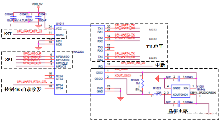
- The pin interruption requires an external pull-up resistance, typically 5.1K. The driver receives and receives data depending on the interrupt signal. If the interrupt signal is abnormal, the subsequence port cannot communicate properly.
- Crystal Vibration Circuit, Requires 1M resistor in parallel with Crystal Vibration
- SPI is connected to the SPI pin of the CPU (Xavier), the sub-serial port outputs TTL level, and the RS signal transceiver is connected
- The RTS pin (only 2/4 of the sub-serial port) is used to control the transceiver/receiver conversion of the RS-485 transceiver in the RS485 automatic transceiver control working mode.
drive
Add Device Tree
- As a SPI slave device, WK2204 SPI bus maximum rate cannot exceed 10M
- INT and RTS are connected to CPU, and these two GPIO resources need to be added to the device tree
- Frequency of Crystal Vibration in Device Tree
_Add the following device tree:
	spi@3230000{			// cpu is nvidia-jetson
		status = "okay";

		spi_test@00 {
			compatible = "wkmic, wk2124spi";
			reg = <0>;

			spi-max-frequency = <10000000>;

			irq_gpio = <&tegra_main_gpio TEGRA194_MAIN_GPIO(T, 0) IRQ_TYPE_LEVEL_LOW>;
			reset_gpio = <&tegra_main_gpio TEGRA194_MAIN_GPIO(M, 3) GPIO_ACTIVE_HIGH>;
		};
	};
Add Driver
- WK2204Official Driver Based on the Rockchip platform and the core-3.1 foundation, remove the relevant rockchip code:
-#include <linux/platform_data/spi-rockchip.h>
... ...

//#ifdef CONFIG_OF
-static int rockchip_spi_parse_dt(struct device *dev)
+static int spi_parse_dt(struct device *dev)
... ...

static int wk2xxx_probe(struct spi_device *spi)
{
	... ...

+	irq = spi_parse_dt(&spi->dev);
+	if(irq < 0)
+		return 1;

	do
	{
		wk2xxx_read_global_reg(spi,WK2XXX_GENA,dat);
		printk(KERN_ERR "wk2xxx_probe()  GENA = 0x%X\n",dat[0]); //GENA=0X30
		wk2xxx_write_global_reg(spi,WK2XXX_GENA,0xf5);
		wk2xxx_read_global_reg(spi,WK2XXX_GENA,dat);
		printk(KERN_ERR "wk2xxx_probe()  GENA = 0x%X\n",dat[0]); //GENA=0X35
		wk2xxx_write_global_reg(spi,WK2XXX_GENA,0xf0);
		wk2xxx_read_global_reg(spi,WK2XXX_GENA,dat);
		printk(KERN_ERR "wk2xxx_probe()  GENA = 0x%X\n",dat[0]); //GENA=0X30
	}while(0);
/test spi //

-	irq = rockchip_spi_parse_dt(&spi->dev);
-	if(irq < 0)
-		return 1;
	... ...
}
... ...

-static int wk2xxx_resume(struct spi_device *spi)
-{
-	#ifdef _DEBUG_WK_FUNCTION
-	printk(KERN_ALERT "%s!!--in--\n", __func__);
-	#endif
-   return 0;
-}
... ...

static struct spi_driver wk2xxx_driver = {
	.driver = {
		.name           = "wk2xxxspi",
		.bus            = &spi_bus_type,
		.owner          = THIS_MODULE,
		.of_match_table = of_match_ptr(rockchip_spi_wk2xxx_dt_match),
	},

	.probe          = wk2xxx_probe,
	.remove         = wk2xxx_remove,
-	.resume         = wk2xxx_resume,
}
- The RST pin level of WK2204 sub-serial port 4 can automatically control the sending and receiving of 485 chips. Official driver defaults to the RST pin pull up, instead of the default pull down:
+#define WK_RS485_FUNCTION
......

static int wk2xxx_startup(struct uart_port *port)//i
{
	... ...

#ifdef WK_RS485_FUNCTION
+	// Channel 4 is set to 485 functions
+	if (s->port.iobase == 4) {
-		wk2xxx_write_slave_reg(s->spi_wk,s->port.iobase,WK2XXX_RS485,0X02);	//default high
+		wk2xxx_write_slave_reg(s->spi_wk,s->port.iobase,WK2XXX_RS485,0X03);	//default low
		wk2xxx_write_slave_reg(s->spi_wk,s->port.iobase,WK2XXX_SPAGE,1);
		wk2xxx_write_slave_reg(s->spi_wk,s->port.iobase,WK2XXX_RRSDLY,0X10);
		wk2xxx_write_slave_reg(s->spi_wk,s->port.iobase,WK2XXX_SPAGE,0);
	}
#endif
	... ...

}
- The baud rate of WK2204 sub-serial port comes from the frequency division of crystal oscillation outside the chip. The official drive adapter is 11.0592 Mhz. Take 16Mhz crystal oscillation as an example, change to:
static void wk2xxx_termios( struct uart_port *port, struct ktermios *termios,
            struct ktermios *old)
{
	... ...

	switch (baud)
	{
		case 600:
-			baud1=0x4;
-			baud0=0x7f;
-			pres=0;
+			baud1=0x6;
+			baud0=0x81;
+			pres=0xb;
			break;
		case 1200:
-			baud1=0x2;
-			baud0=0x3F;
-			pres=0;
+			baud1=0x3;
+			baud0=0x40;
+			pres=0x5;
			break;
		case 2400:
			baud1=0x1;
-			baud0=0x1f;
-			pres=0;
+			baud0=0x9f;
+			pres=0xb;
			break;
		case 4800:
			baud1=0x00;
-			baud0=0x8f;
-			pres=0;
+			baud0=0xcf;
+			pres=0x5;
			break;
		case 9600:
			baud1=0x00;
-			baud0=0x47;
-			pres=0;
+			baud0=0x67;
+			pres=0x3;
			break;
		case 19200:
			baud1=0x00;
-			baud0=0x23;
-			pres=0;
+			baud0=0x33;
+			pres=0x1;
			break;
		case 38400:
			baud1=0x00;
-			baud0=0x11;
-			pres=0;
+			baud0=0x19;
+			pres=0x1;
			break;
		case 76800:
			baud1=0x00;
-			baud0=0x08;
-			pres=0;
+			baud0=0x0c;
+			pres=0;
			break;
		case 1800:
-			baud1=0x01;
-			baud0=0x7f;
-			pres=0;
+			baud1=0x2;
+			baud0=0x2a;
+			pres=0x9;
			break;
		case 3600:
-			baud1=0x00;
-			baud0=0xbf;
-			pres=0;
+			baud1=0x1;
+			baud0=0x14;
+			pres=0xc;
			break;
		case 7200:
			baud1=0x00;
-			baud0=0x5f;
-			pres=0;
+			baud0=0x89;
+			pres=0xe;
			break;
		case 14400:
			baud1=0x00;
-			baud0=0x2f;
-			pres=0;
+			baud0=0x44;
+			pres=0x7;
			break;
		case 28800:
			baud1=0x00;
-			baud0=0x17;
-			pres=0;
+			baud0=0x21;
+			pres=0xc;
			break;
		case 57600:
			baud1=0x00;
-			baud0=0x0b;
-			pres=0;
+			baud0=0x10;
+			pres=0x6;
			break;
		case 115200:
			baud1=0x00;
-			baud0=0x05;
-			pres=0;
+			baud0=0x07;
+			pres=0xb;
			break;
		case 230400:
			baud1=0x00;
-			baud0=0x02;
-			pres=0;
+			baud0=0x03;
+			pres=0x6;
			break;
		default:
			baud1=0x00;
			baud0=0x00;
			pres=0;
			break;
	}
	... ...

}
debugging
View boot loads
_Driver loads successfully and generates four serial devices under / dev: ttysWK0, ttysWK1, ttysWK2, ttysWK3. Enter "dmesg | grep wk" or "ls/dev/ttysWK*" to see if the driver loaded successfully, as shown in the diagram:
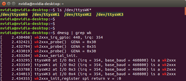
_If the driver loading fails, detect if the RST signal is pulled up before the driver loading.
Check Serial Communication
_Windows System Installation Serial Debugging Assistant; The Ubuntu system recommends using the serial communication tool minicom (Reference) Usage method).
Data is out of order or missing
- Check crystal vibration
- Check harness
- Detect INT signal
- Change debugging tools
RS485 can only be received or not sent
- Whether the driver enables 485 custom transceiver control functions
- Oscilloscope Detecting RTS Signal
System Interrupt Response Exception
_If the system keeps responding to interruptions without data communication, as shown in the figure:
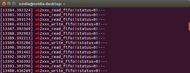
_Check the source of the interrupt to interrupt the DEBUG information (_DEBUG_WK_IRQ) if the register display chip does not issue an interrupt:
- Check the interrupt mode of the driver settings and whether the low level triggers.
- The oscilloscope detects the INT pin level before and after data communication. If it keeps pulling down, check the pull-up resistance value of the connection.
Reflection
_4 routes of uart data receipt are responded to by gpio interruption, which leads to higher CPU usage.