1. Briefly describe osi seven layer model and TCP/IP five layer model
- OSI reference model
The Open System Interconnection Reference Model is a conceptual model proposed by the international organization for standardization. It divides the computer network architecture into the following seven layers:
Application Layer: as a window for users and application processes to access the network. End users and application processes can realize network communication, resource contribution and other operations with remote users or application processes through the protocols provided by them. Some common Application Layer protocols are: HTTP, HTTPS, FTP, TELNET, SSH, SMTP, POP3, etc.
Presentation Layer: it is mainly concerned with the syntax and semantics of the information exchanged between the two systems. It plays the role of translator in network communication and is mainly engaged in the encoding and conversion, encryption, decryption, compression and decompression of the data exchanged between the two systems.
Session Layer: the Session Layer is used to establish, maintain and synchronize the interaction between communication devices. It acts as a dialog controller in network communication.
Transport Layer: the Transport Layer is located in layer 4 and provides two main transmission modes: reliable transmission mode (TCP) and unreliable transmission mode (UDP). The reliable transmission mode (TCP) is used to establish the end-to-end connection between the source and the target, and the receiving response and timeout retransmission mechanism ensure the integrity and reliability of the transmitted data. The unreliable transmission mode (UDP) is used to realize efficient and fast data communication without reliable data communication.
Protocol data unit (PDU): TCP: segment, UDP: message
Network Layer: provides networking, addressing, routing, packaging and other functions. It can select the optimal path of data transmission between source and destination according to network conditions, service priority and other factors; Representative protocols include IP, IPX, RIP, OSPF, etc.
Protocol data unit (PDU): packet or packet
Data Link Layer: its main task is to transmit data in frame without error on the line between two adjacent nodes. The Data Link Layer decomposes the data into frames, and then transmits the frames in sequence. Each frame includes data and necessary control information (including synchronization information, address information, error control information, flow control information, etc.).
This layer includes two sub layers: Logical Link Control Layer and Media Access Control Layer. Representatives of this layer protocol include SDLC, HDLC, PPP, STP, frame relay, etc.
Protocol data unit (PDU): frame
Physical Layer: the main function of the Physical Layer is to transfer bits from one node to another. It establishes, maintains and deactivates physical connections and specifies mechanical, electrical and program network interface specifications.
TCP/IP five layer model:
Composition: application layer, transmission layer, Internet layer, data link layer and physical layer;
The application layer corresponds to the application layer, presentation layer and session layer of the OSI reference model;
TCP/IP four layer model:
Composition: application layer, transport layer, Internet layer and network interface layer
Network interface layer: strictly speaking, the network interface layer is not an independent layer, but an interface. TCP/IP does not define any specific protocol for it. The network interface layer is responsible for sending the data of the network layer, or receiving data frames from the network layer, extracting IP datagrams and submitting them to the Internet layer.
Internet layer: the function is similar to that of the network in the OSI seven layer model, dealing with networking, addressing, routing, packaging and other matters.
2. Summarize and describe TCP three handshakes and four waves
- TCP triple handshake
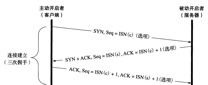
To establish a TCP connection, you need to go through three steps called "three handshakes", as shown below:
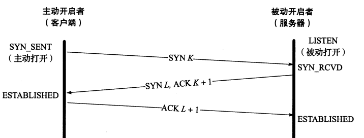
The status transition is shown in the following figure:
- Usually, the client, as the active initiator of TCP connection establishment, first sends a data message segment ("segment 1") requesting the establishment of TCP connection to the server. SYN in "segment 1" is set, and the serial number field is the initial serial number (ISN) selected by yourself ©), And additional options; [at this time, the client state is switched from CLOSED to SYN-SENT, and the server is in LISTEN]
- When the server receives "segment 1" from the client, it will send a corresponding data message segment ("segment 2"). The SYN and ACK fields in "segment 2" are set, including its own initial serial number (ISN(s)) and confirm that the serial number field is the serial number ISN of "segment 1" ©+ 1. [server status: from LISTEN to SYN-RECV, client status: SYN-SENT]
- After receiving "segment 2" from the server, the client will send a response data message segment ("segment 3") to the server. In "segment 3", ACK is set and the serial number is ISN ©+ 1. The ACK sequence is: ISN(s)+1. After the server receives the message segment, the TCP connection is ESTABLISHED successfully. [client status: SYN-SENT is converted to ESTABLISHED; server status: SYN-RECV is converted to ESTABLISHED]
verification:
Introduction to experimental environment:
Start two centos7 hosts, hostA: 10.48.4.7; hostB: 10.48.4.254
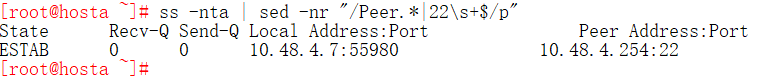
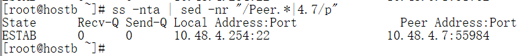
- hostA starts the SSH client to connect to the ssh server on hostB, and the tcp connection is established. When the handshake succeeds three times, as shown in the following figure:

It can be seen that after three successful handshakes, the connection from hostA to hostB has been established.
- Block the first handshake and view the related status:
As shown in the following figure, set a firewall to block the syn data message segment of the first handshake:
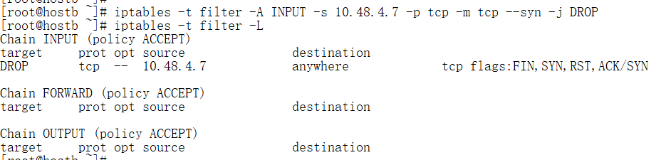
Initiate a TCP connection establishment request with hostB on hostA. The data message segment is shown in the figure below. Timeout retransmission occurs and the first handshake is successfully prevented:

Check the connection status of hostA (TCP client), as shown in the following figure, in SYN-SENT status:

Check the connection status of hostB (TCP server), as shown in the figure below, and it is in LISTEN status:

- Block the second handshake and view the relevant status:
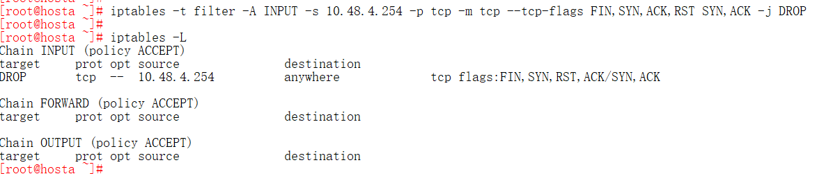
Configure firewall on hostA (client) to block tcp data message segments with syn and ACK set;
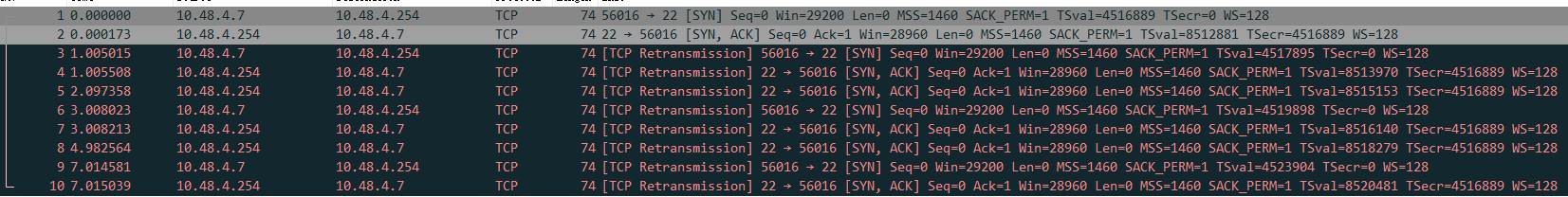
As shown in the figure below, timeout retransmission occurs, and the client does not receive the response data message segment of the server, so the second handshake is successfully blocked:
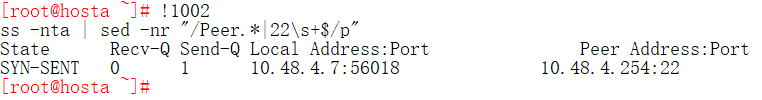
Check the status of the client and it is still in SYN-SENT, as shown in the following figure:
Check the status of the server. LISTEN - > syn-recv is shown in the following figure:
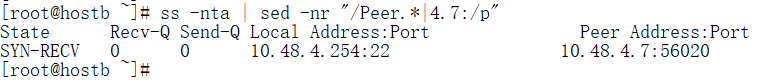
- Block the third handshake phase and view the relevant status:
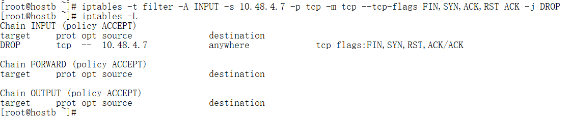
On the hostB (server), block the data segment with only ACK set through the firewall, so as to prevent the third handshake. It is as follows:
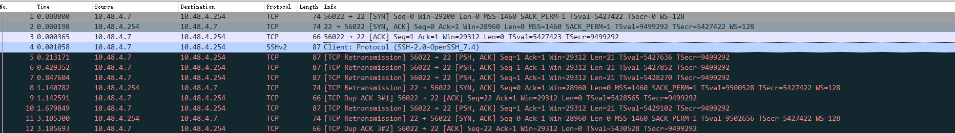
Check the data segment between the client and the server, as shown in the figure below. Timeout retransmission occurs, the server does not receive the data segment of the third handshake, and the third handshake is successfully blocked:
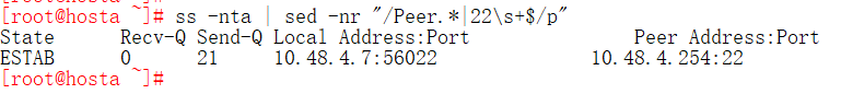
View the client status. The client is SYN-SENT - > established, indicating that the connection has been established:
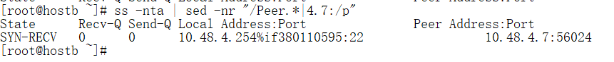
Check the server status, and it is still in SYN-RECV status:
[Summary:]
Data message segment:
First handshake: [Client initiated] SYN set, SEQ = isn (c)
Second handshake: [initiated by the server] SYN and ACK are set, SEQ = isn (s), ACK = isn (c) + 1
The third Handshake: the [Client initiated] ack is set, SEQ = isn (c) + 1, ACK = isn (s) + 1
Status change:
First handshake: [Client] CLOSED - > syn_ Send [server] LISTEN
Second handshake: [Client] SYN_SENT [server] LISTEN - > syn_ RECV
Third Handshake: [Client] SYN_SENT - > established [server] SYN_RECV —> ESTABLISHED
- TCP's four waves
TCP disconnection requires 4 this waving operation. In principle, the active initiator sends the data message segment with FIN set to the passive receiver twice, and the passive receiver sends the data message segment with ACK set to respond to it.
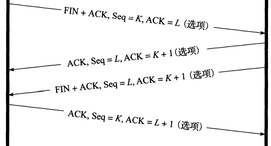
1. The active closure of the connection sends a FIN segment indicating the current serial number K that the receiver wants to see. The FIN segment also contains an ACK segment to confirm the latest data sent by the other party.
2. The connected passive closer adds 1 to the value of K as the ACK value in response to indicate that it has successfully received the FIN sent by the active closer. At this point, the upper application will be informed that the other end of the connection has made a request to close. Typically, this will cause the application to initiate its own shutdown. Then, the passive shut-down person changes his identity to the active shut-down person and sends his own FIN. The serial number L of the message segment.
3. In order to close the connection, the last sent message segment also contains an ACK to confirm the last FIN. It should be noted that if FIN is lost, the sender will retransmit until an ACK acknowledgement is received.
3. Describe the difference between TCP and UDP
- tcp is a reliable connection oriented protocol, while UDP is a unreliable non connection oriented protocol;
- tcp supports timeout retransmission mechanism, but UDP does not;
- tcp has congestion control function, but UDP does not support it;
- Different agreement numbers; TCP protocol number: 6, UDP protocol number: 17;
- TCP supports the reordering mechanism of unordered data segments, but UDP does not support it;
- TCP has an acceptance confirmation mechanism, but UDP does not;
- UDP data transmission speed is fast, while TCP loses some data transmission speed due to reliability mechanism;
- TCP is generally used in application scenarios requiring high reliability such as file transmission and download, while UDP is generally used in environments where voice or video streams require real-time response and low delay.
4. Implementation of network card binding bond0
Experimental environment:
OS : centos7
CentOS 7 has network card devices: eth3 and eth4
Virtual machine: vmware workstation 16 pro
- Check whether the binding module is loaded
[root@route-c7 ~]# lsmod | grep bonding
bonding               152979  0
[root@route-c7 ~]#
If not loaded:
[root@route-c7 ~]# modprobe bonding     #Add binding module
[root@route-c7 ~]# lsmod | grep bonding
bonding               152979  0
[root@route-c7 ~]#
If the kernel does not have its own binding module: Please recompile the kernel and select the binding function
- Configure the active and standby policies of bonding and use multiple network cards to improve fault tolerance.
Method 1: manually modify the configuration file to achieve:
- Add the configuration file / etc / sysconfig / network scripts / ifcfg-bond0 for bond0
[root@route-c7 ~]# cat <<EOF > /etc/sysconfig/network-scripts/ifcfg-bond0
>NAME=bond0
>TYPE=bond
>DEVICE=bond0
>BOOTPROTO=none
>ONBOOT=yes
>BONDING_OPTS="mode=1 miimon=100 fail_over_mac=active"
>IPADDR=10.48.4.100
>PREFIX=12
>EOF
Parameter interpretation:
mode=1: indicates the mode of bonding. Mode 1: active backup;
miimon=100: specify the monitoring frequency of MII link in milliseconds; The default value is 0, which means MII link monitoring is turned off.
fail_over_mac:
Specify whether all slave interfaces are set to the same MAC address in the active backup mode of the master and standby, or perform special processing on the bound MAC address according to the selected policy after enabling. Possible values are:
- none or 0: the default value is to turn off fail_over_mac enables all slave interfaces in active backup mode to bind
Have the same mac address; - active or 1: "active" means that the mac address of the bond interface should always be equal to the mac address of the slave interface currently in active state. The mac address of the slave interface will not change, but the address of the bond interface will change during failover.
- follow or 2: "follow" means that the mac address of the bond interface is usually the first added slave interface at the beginning. The slave interface in the backup state will not change its mac address at the beginning, but in the process of failover, the mac address of the switched slave interface will change to be the same as that of the bond interface.
- Add configuration files ifcfg-eth3 and ifcfg-eth4 for eth3 and eth4
[root@route-c7 ~]# cat <<EOF > /etc/sysconfig/network-scripts/ifcfg-eth3
>NAME=eth3
>DEVICE=eth3
>ONBOOT=yes
>MASTER=bond0
>SLAVE=yes
>BOOTPROTO=none
>EOF
[root@route-c7 ~]# cat <<EOF > /etc/sysconfig/network-scripts/ifcfg-eth4
>NAME=eth4
>DEVICE=eth4
>ONBOOT=yes
>BOOTPROTO=none
>MASTER=bond0
>SLAVE=yes
>EOF
- Restart the network.service service
[root@route-c7 ~]# systemctl restart network
- Check for success
[root@route-c7 ~]# ip address
1: eth3: <BROADCAST,MULTICAST,SLAVE,UP,LOWER_UP> mtu 1500 qdisc pfifo_fast master bond0 state UP group default qlen 1000
    link/ether 00:50:56:aa:44:44 brd ff:ff:ff:ff:ff:ff
2: eth4: <BROADCAST,MULTICAST,SLAVE,UP,LOWER_UP> mtu 1500 qdisc pfifo_fast master bond0 state UP group default qlen 1000
    link/ether 00:0c:29:77:34:f0 brd ff:ff:ff:ff:ff:ff
11: bond0: <BROADCAST,MULTICAST,MASTER,UP,LOWER_UP> mtu 1500 qdisc noqueue state UP group default qlen 1000
    link/ether 00:50:56:aa:44:44 brd ff:ff:ff:ff:ff:ff
    inet 10.48.4.100/12 brd 10.63.255.255 scope global noprefixroute bond0
       valid_lft forever preferred_lft forever
    inet6 fe80::250:56ff:feaa:4444/64 scope link
       valid_lft forever preferred_lft forever
[root@route-c7 ~]# cat /proc/net/bonding/bond0
Ethernet Channel Bonding Driver: v3.7.1 (April 27, 2011)

Bonding Mode: fault-tolerance (active-backup) (fail_over_mac active)
Primary Slave: None
Currently Active Slave: eth3
MII Status: up
MII Polling Interval (ms): 100
Up Delay (ms): 0
Down Delay (ms): 0

Slave Interface: eth3
MII Status: up
Speed: 1000 Mbps
Duplex: full
Link Failure Count: 0
Permanent HW addr: 00:50:56:aa:44:44
Slave queue ID: 0

Slave Interface: eth4
MII Status: up
Speed: 1000 Mbps
Duplex: full
Link Failure Count: 0
Permanent HW addr: 00:0c:29:77:34:f0
Slave queue ID: 0
[root@route-c7 ~]#
Method 2: use the nmcli command to configure the file:
[root@route-c7 ~]# nmcli con add con-name bond0 ifname bond0 type bond mode active-backup  miimon 100 ipv4.method manual ipv4.addresses 10.48.4.100/12 autoconnect yes
[root@route-c7 ~]# nmcli con add con-name eth3 ifname eth3 type bond-slave master bond0 autoconnect yes
[root@route-c7 ~]# nmcli con add con-name eth4 ifname eth4 type bond-slave master bond0 autoconnect yes
[root@route-c7 ~]# cat /etc/sysconfig/network-scripts/ifcfg-bond0
BONDING_OPTS=mode=active-backup
TYPE=Bond
BONDING_MASTER=yes
PROXY_METHOD=none
BROWSER_ONLY=no
BOOTPROTO=none
IPADDR=10.48.4.100
PREFIX=12
DEFROUTE=yes
IPV4_FAILURE_FATAL=no
IPV6INIT=yes
IPV6_AUTOCONF=yes
IPV6_DEFROUTE=yes
IPV6_FAILURE_FATAL=no
IPV6_ADDR_GEN_MODE=stable-privacy
NAME=bond0
UUID=aaf4a6bd-114b-42c8-96e7-3a5a87465d7e
DEVICE=bond0
ONBOOT=yes
[root@route-c7 ~]#
[root@route-c7 ~]# cat /etc/sysconfig/network-scripts/ifcfg-eth3
TYPE=Ethernet
NAME=eth3
UUID=de8e299f-93c3-472e-b728-ded47bae6857
DEVICE=eth3
ONBOOT=yes
MASTER=bond0
SLAVE=yes
[root@route-c7 ~]#
[root@route-c7 ~]# cat /etc/sysconfig/network-scripts/ifcfg-eth4
TYPE=Ethernet
NAME=eth4
UUID=a445c665-42c6-44ce-b30d-331e14655adf
DEVICE=eth4
ONBOOT=yes
MASTER=bond0
SLAVE=yes
[root@route-c7 ~]#
[root@route-c7 ~]# cat /proc/net/bonding/bond0
Ethernet Channel Bonding Driver: v3.7.1 (April 27, 2011)

Bonding Mode: fault-tolerance (active-backup)
Primary Slave: None
Currently Active Slave: eth3
MII Status: up
MII Polling Interval (ms): 100
Up Delay (ms): 0
Down Delay (ms): 0

Slave Interface: eth3
MII Status: up
Speed: 1000 Mbps
Duplex: full
Link Failure Count: 0
Permanent HW addr: 00:50:56:aa:44:44
Slave queue ID: 0

Slave Interface: eth4
MII Status: up
Speed: 1000 Mbps
Duplex: full
Link Failure Count: 0
Permanent HW addr: 00:0c:29:77:34:f0
Slave queue ID: 0
[reference link]