Voice communication scheme
System level solutions and self built protocols
windows platform, linux platform, embedded linux platform, mcu platform
1. Voice solution of wired communication developed on Embedded Linux
This scheme is developed on Embedded Linux. The audio scheme is based on ALSA. The voice communication is related to user space. It is a top-level solution. Due to the wired communication, the network environment is not particularly bad compared with the wireless communication, and there are not many packet loss compensation measures, mainly PLC, RFC2198, etc.
2. Voice solution for traditional wireless communication developed on Android mobile phone
This scheme is developed on Android mobile phone, which is a traditional voice communication scheme on mobile phone (relative to APP voice communication). Android is based on Linux, so ALSA will also be used, but mainly for control, such as the configuration of codec chip. The driver, codec, pre-processing and post-processing related to audio data are developed on Audio DSP, and the network side is developed on CP (communication processor), which is a bottom-level solution. The software block diagram of the scheme is as follows:
System level
Sound card is also called audio frequency The sound effect card is the most basic part of the computer multimedia system. It is the realization of acoustic wave/digital signal A kind of mutual conversion Hardware . The basic function of sound card is to Microphone , tape, optical raw sound signal To convert, output to Headset,speaker,an amplifier,recorder Equivocal equipment , or by Music Equipment digital interface( MIDI )To produce the sound of a synthetic instrument
All computer motherboards basically have integrated sound cards. If there is a professional requirement, you will buy another independent sound card, just like a professional player who buys an independent video card and a manual dog head
Sound card drive
For audio processing technology, there are mainly the following:
- Collect microphone input
- Acquisition sound card output
- Send audio data to sound card for playing
- Mix multiple audio inputs
Calling sound card API provided by Windows Platform Kernel
1, MME (MultiMedia Extensions)
MME is the interface provided by winmm.dll and the first generation API under Windows platform. The advantage is that it is simple to use and can meet the business requirements in general scenarios. The disadvantage is that it has high latency and some advanced functions cannot be realized.
Two. XAudio2
Also part of DirextX, to replace DirectSound. The audio components in the DirextX suite are mostly used in games and support hardware acceleration, so they have lower latency than MME.
Three. Core Audio API
Vista system began to introduce a new architecture. It is an interface provided by COM. In user mode, it is at the bottom. Several API s mentioned above will eventually use it! It has the strongest function and the best performance, but the interface is complex and cumbersome to use.
Four. Wasapi will do (high performance, but more complex)
The Wave series API functions are mainly used to collect the microphone input (using the Wave in series API functions) and control the sound playback (using the post Wave out series functions).
1. Use WaveIn series API functions to realize microphone input collection
API functions involved:
-
waveInOpen
Open the audio collection device, and the device handle will be returned after success. The handle needs to be used by subsequent API s
The calling module needs to provide a callback function (waveInProc) to receive the collected audio data
-
waveInClose
Turn off the audio acquisition module
After success, the device handle returned by waveInOpen will no longer be valid
-
waveInPrepareHeader
Prepare space for audio collection data cache
-
waveInUnprepareHeader
Clear the data cache of audio collection
-
waveInAddBuffer
Provide the prepared audio data cache to the audio collection device
waveInPrepareHeader needs to be called before calling the API
-
waveInStart
Control the audio acquisition equipment to start the acquisition of audio data
-
waveInStop
Control the audio acquisition equipment to stop the acquisition of audio data
After the audio collection device collects the audio data, it will call the callback function set in waveInOpen.
The parameters include a message type, according to which corresponding operations can be performed.
If the WIM data message is received, it indicates that new audio data has been collected, so that these audio data can be processed as required.
(to be added later)
2. Use Core Audio to capture the output of sound card
The interfaces involved are:
-
IMMDeviceEnumerator
-
IMMDevice
-
IAudioClient
-
IAudioCaptureClient
Main process:
-
Create a Multimedia Device Enumerator
-
Obtain the sound card interface (IMMDevice) through the Multimedia Device Enumerator
-
Obtain the audio client interface (IAudioClient) through the audio interface
-
Through the iaudioclient, we can obtain the audio parameters of the output of the sound card, initialize the sound card, obtain the size of the output buffer of the sound card, and start / stop the collection of the output of the sound card
-
Through the audio capture client interface (IAudio capture client), the output data of the audio card can be acquired and the internal buffer can be controlled
(to be added later)
3. Common mixing algorithms
The mixing algorithm is to calculate the multi-channel audio input signal according to some rules (the multi-channel audio signal is added and then limited), to get a mixed audio, and take this as the output process.
I have also done this work. I have searched the following basic mixing algorithms:
-
Add multiple audio input signals directly and take sum as output
-
Add multiple audio input signals directly and divide by the number of mixing channels to prevent overflow
-
Add the multiple audio input signals directly to get the sum, and then perform the Clip operation (limit the data between the maximum value and the minimum value). If there is any overflow, set the maximum value
-
After the multi-channel audio input signals are added and summed directly, they are saturated and distorted when they are close to the maximum value
-
After adding and summing the multiple audio input signals directly, normalize them and multiply all the coefficients to normalize the amplitude
-
The attenuation factor is used to limit the amplitude after the sum of multiple audio input signals is added directly
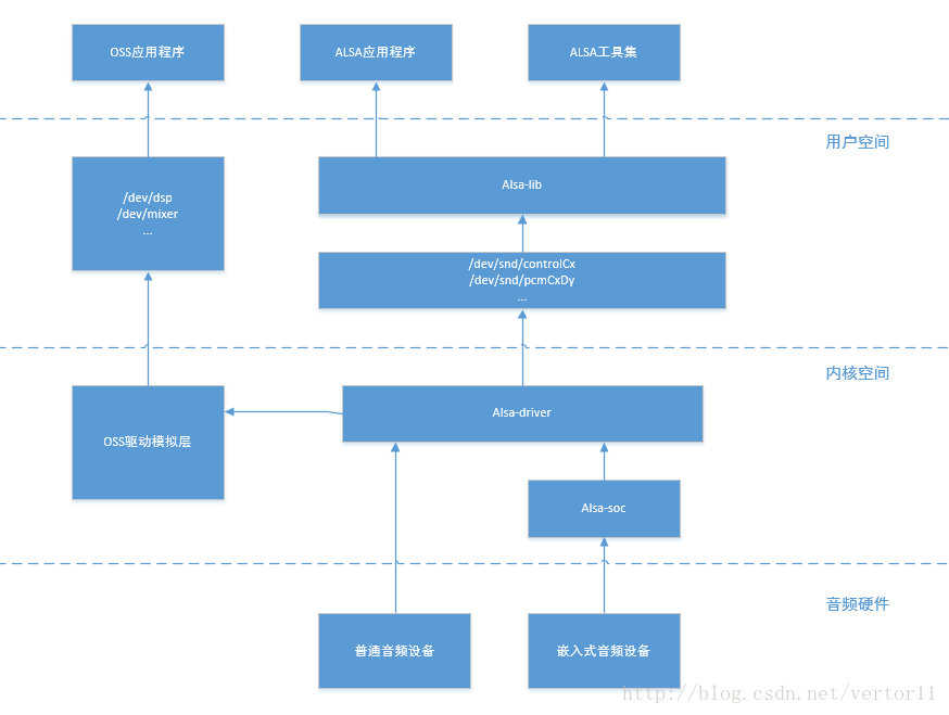
Linux platform kernel provides calling sound card API
ALSA is the mainstream Audio Architecture of linux
Is an open source project with community maintenance: http://www.alsa-project.org/
include:
1. Kernel driver package alsa driver
2. User space library alsa Lib
3. Add in Library plug-in package alsa libplugins
4. Audio processing toolset alsa utils
5. Other audio processing tools package alsa tools
6. Special audio firmware support package alsa firmware
7. Python binding package pyalsa Lib
8.OSS interface compatibility package alsa OSS
9. In kernel space, alsa SOC is actually a further encapsulation of alsa driver. It provides some column enhanced functions for embedded devices.
1. Operating instructions
install
sudo apt install libasound2-dev
Technological process
- open device
- Allocate parameter memory
- Fill in default parameters
- Set parameters (see for details ALSA - PCM interface)
- Number of channels
- Sampling rate (code rate, used to specify time and file size, frames/s)
- Number of frames (the length of data read per time is related to this parameter)
- Data format (affects output data, cache size)
- Device access type (direct read / write, memory mapping, interleaved mode, non interleaved mode)
- Read and write data
A simple example
Include header file
#include <alsa/asoundlib.h>
Check the device and determine the device name according to the last two numbers. Usually, default is OK
aplay -L
Define the relevant parameters, and record and play the sound through the same steps, and define them together
// The device name, which is the default, can also select "hw:0,0","plughw:0,0", etc
const char *device = "default";
// device handle
// There are two definitions below. They are distinguished according to the prefix. C - > capture, P - > playback. The representation parameters without a prefix are the same
snd_pcm_t *chandle;
snd_pcm_t *phandle;
// Hardware parameters
snd_pcm_hw_params_t *cparams;
snd_pcm_hw_params_t *pparams; // Data access type, read-write mode: memory mapping or read-write, snd? PCM? Access? T access? Type= SND_PCM_ACCESS_RW_INTERLEAVED; // Format, snd? PCM? Format? T format= SND_PCM_FORMAT_S16_LE; // Code rate, sampling rate, 8000Hz,44100Hz unsigned int rate = 44100; // Channel number unsigned int channels = 2; // The number of frames is 32 snd ﹣ PCM ﹣ uframes ﹣ t frames = 32; // The following is the optional parameter unsigned int bytes_per_frame; // Software resampled unsigned int soft_resample;
open device
snd_pcm_open(&chandle, device, SND_PCM_STREAM_CAPTURE, 0);
snd_pcm_open(&phandle, device, SND_PCM_STREAM_PLAYBACK, 0);
Add a wrong judgment
int err;
if ((err = snd_pcm_open(&chandle, device, SND_PCM_STREAM_CAPTURE, 0)) < 0)
{
    std::cout << "Capture device open failed.";
}
if ((err = snd_pcm_open(&phandle, device, SND_PCM_STREAM_PLAYBACK, 0)) < 0)
{
    std::cout << "Playback device open failed."; }
Set the parameters, and the error judgment will not be added here, otherwise it will be a little long
// First, calculate the size of each frame of data bytes_per_frame = snd_pcm_format_width(format) / 8 * 2; // Calculate the size of the cache space that needs to be allocated buffer_size = frames * bytes_per_frame; // Allocate space for parameters snd_pcm_hw_params_alloca(¶ms); // Fill parameter space snd_pcm_hw_params_any(handle, params); // Set data access method snd_pcm_hw_params_set_access(handle, params, access_type); // Set format (handle, params, format); // Set snd? PCM? HW? Params? Set? Channels (handle, params, channels); // Set the sampling rate snd? PCM? HW? Params? Set? Rate? Near (handle, params, & rate, 0); // Optional, unchanged / / set buffer size = period size * 2; snd_pcm_hw_params_set_buffer_size_near(handle, params, &buffer_size); // Set the segment size. period is similar to segment in OSS. period = buffer size / 2; snd_pcm_hw_params_set_period_size_near(handle, params, &period_size, 0)); //Set the parameter snd? PCM? HW? Params (handle, params);
Read and write data
// Allocate cache space. The size is calculated by buffer_size
char *buffer = (char *)malloc(buffer_size);
// Read and write data
snd_pcm_readi(chandle, buffer, frames);
snd_pcm_writei(phandle, buffer, frames);
Loop Playback
while(1)
{
    snd_pcm_readi(chandle, buffer, frames);
    snd_pcm_writei(phandle, buffer, frames);
}
Capture audio data to the file stream for a certain period of time
ofstream output("test.pcm", ios::trunc);

int loop_sec;
int frames_readed;
loop_sec = 10;
unsigned long loop_limit; // Calculate loop? Limit = loop? Sec* rate; for (size_t i = 0; i < loop_limit; ) { // It is also necessary to determine whether the return value is negative frames ﹣ read= snd_pcm_readi(chandle, buffer, frames); output.write(buffer, buffer_size); i += frames_readed; }
Shut down device, release pointer
snd_pcm_close(chandle);
snd_pcm_close(phandle);
free(buffer);
During playback, there may be a "Broken pipe" error. Add the following to prepare the device again
err = snd_pcm_writei(handle, input_buffer, frames);
if (err == -EPIPE)
{
    snd_pcm_prepare(handle);
    continue;
    // perhaps
    // return 0;
}
Complete example


 1 #ifndef ALSA_AUDIO_H
 2 #define ALSA_AUDIO_H
 3
 4 #include <QObject>
 5
 6 #include <alsa/asoundlib.h>
 7
 8 class ALSA_Audio : public QObject
 9 {
10     Q_OBJECT
11 public:
12     explicit ALSA_Audio(QObject *parent = nullptr);
13
14
15     void capture_start();
16     void capture_stop();
17     /**
18      * @brief Read audio data
19      * @param buffer Audio data
20      * @param buffer_size Audio data size
21      * @param frames Number of audio frames read
22      * @return 0 Success, - 1 Failure
23      */
24     int audio_read(char **buffer, int *buffer_size, unsigned long *frames);
25
26     void playback_start();
27     void playback_stop();
28     /**
29      * @brief audio_write Play audio
30      * @param buffer Audio data
31      * @param frames Number of audio frames played
32      * @return 0 Success, - 1 Failure
33      */
34     int audio_write(char *buffer);
35
36
37
38 private:
39     bool m_is_capture_start;
40     snd_pcm_t *m_capture_pcm;
41     char *m_capture_buffer;
42     unsigned long m_capture_buffer_size;
43     snd_pcm_uframes_t m_capture_frames;       // Frames read at a time
44
45
46     bool m_is_playback_start;
47     snd_pcm_t *m_playback_pcm;
48     snd_pcm_uframes_t m_playback_frames;       // Frames written at a time
49
50     /**
51      * @brief ALSA_Audio::set_hw_params
52      * @param pcm
53      * @param hw_params
54      * @param rate sampling frequency
55      * @param format format
56      * @param channels Number of channels
57      * @param frames Number of frames read and write at a time
58      * @return
59      */
60     int set_hw_params(snd_pcm_t *pcm, unsigned int rate, snd_pcm_format_t format, unsigned int channels, snd_pcm_uframes_t frames);
61
62
63
64 signals:
65
66 public slots:
67 };
68
69 #endif // ALSA_AUDIO_H
  1 #include "alsa_audio.h"
  2 #include "global.h"
  3
  4 #include <QDebug>
  5
  6 #include <math.h>
  7 #include <inttypes.h>
  8
  9
 10
 11 ALSA_Audio::ALSA_Audio(QObject *parent) : QObject(parent)
 12 {
 13     m_is_capture_start = false;
 14     m_is_playback_start = false;
 15 }
 16
 17
 18
 19 int ALSA_Audio::set_hw_params(snd_pcm_t *pcm, unsigned int rate, snd_pcm_format_t format, unsigned int channels, snd_pcm_uframes_t frames)
 20 {
 21     snd_pcm_uframes_t period_size;          // The number of frames needed in a processing cycle
 22     snd_pcm_uframes_t hw_buffer_size;      // Hardware buffer size
 23     snd_pcm_hw_params_t *hw_params;
 24     int ret;
 25     int dir = 0;
 26
 27
 28
 29     // Initialize hardware parameter structure
 30     snd_pcm_hw_params_malloc(&hw_params);
 31     // Set default hardware parameters
 32     snd_pcm_hw_params_any(pcm, hw_params);
 33
 34     // The following are the required hardware parameters for setting
 35
 36     // Set audio data recording method
 37     CHECK_RETURN(snd_pcm_hw_params_set_access(pcm, hw_params, SND_PCM_ACCESS_RW_INTERLEAVED));
 38     // Format. Use 16 bit sample size, small end mode( SND_PCM_FORMAT_S16_LE)
 39     CHECK_RETURN(snd_pcm_hw_params_set_format(pcm, hw_params, format));
 40     // Set the number of audio channels
 41     CHECK_RETURN(snd_pcm_hw_params_set_channels(pcm, hw_params, channels));
 42     // Sampling frequency, one frame data at a time
 43     //CHECK_RETURN(snd_pcm_hw_params_set_rate_near(pcm, hw_params, &rate, &dir));          // Set similar values
 44     CHECK_RETURN(snd_pcm_hw_params_set_rate(pcm, hw_params, rate, dir));
 45     // The number of frames needed in a processing cycle
 46     period_size = frames * 5;
 47     CHECK_RETURN(snd_pcm_hw_params_set_period_size_near(pcm, hw_params, &period_size, &dir)); // Set similar values
 48 //    // Hardware buffer size, Units: frame( frame)
 49 //    hw_buffer_size = period_size * 16;
 50 //    CHECK_RETURN(snd_pcm_hw_params_set_buffer_size_near(pcm, hw_params, &hw_buffer_size));
 51
 52     // Write parameters to pcm drive
 53     CHECK_RETURN(snd_pcm_hw_params(pcm, hw_params));
 54
 55     snd_pcm_hw_params_free(hw_params);     // Release what is no longer in use hw_params space
 56
 57     printf("one frames=%ldbytes\n", snd_pcm_frames_to_bytes(pcm, 1));
 58     unsigned int val;
 59     snd_pcm_hw_params_get_channels(hw_params, &val);
 60     printf("channels=%d\n", val);
 61
 62     if (ret < 0) {
 63         printf("error: unable to set hw parameters: %s\n", snd_strerror(ret));
 64         return -1;
 65     }
 66     return 0;
 67 }
 68
 69
 70 void ALSA_Audio::capture_start()
 71 {
 72     m_capture_frames = 160;     // Here 160 is a fixed value, which is used for both sending and receiving
 73     unsigned int rate = 8000;                               // sampling frequency
 74     snd_pcm_format_t format = SND_PCM_FORMAT_S16_LE;        // Use 16 bit sample size, small end mode
 75     unsigned int channels = 1;                              // Number of channels
 76     int ret;
 77
 78     if(m_is_capture_start)
 79     {
 80         printf("error: alsa audio capture is started!\n");
 81         return;
 82     }
 83
 84     ret = snd_pcm_open(&m_capture_pcm, "plughw:1,0", SND_PCM_STREAM_CAPTURE, 0);       // Use plughw:0,0
 85     if(ret < 0)
 86     {
 87         printf("snd_pcm_open error: %s\n", snd_strerror(ret));
 88         return;
 89     }
 90
 91     // Set hardware parameters
 92     if(set_hw_params(m_capture_pcm, rate, format, channels, m_capture_frames) < 0)
 93     {
 94         return;
 95     }
 96
 97     // Use buffer Save the data from one-time processing
 98     m_capture_buffer_size = m_capture_frames * static_cast<unsigned long>(snd_pcm_format_width(format) / 8 * static_cast<int>(channels));
 99     m_capture_buffer_size *= 5;         // * 5 Indicates that 5 times of cache space is used
100     printf("snd_pcm_format_width(format):%d\n", snd_pcm_format_width(format));
101     printf("m_capture_buffer_size:%ld\n", m_capture_buffer_size);
102     m_capture_buffer = static_cast<char *>(malloc(sizeof(char) * m_capture_buffer_size));
103     memset(m_capture_buffer, 0, m_capture_buffer_size);
104
105     // Get the time required for one processing, unit us
106     // 1/rate * frames * 10^6 = period_time, That is, the time required to acquire a frame * Number of frames required for one processing * 10^6 = Time required for one processing (unit us)
107     // snd_pcm_hw_params_get_period_time(m_capture_hw_params, &m_period_time, &dir);
108
109     m_is_capture_start = true;
110 }
111
112 void ALSA_Audio::capture_stop()
113 {
114     if(m_is_capture_start == false)
115     {
116         printf("error: alsa audio capture is not start!");
117         return;
118     }
119
120     m_is_capture_start = false;
121
122     snd_pcm_drain(m_capture_pcm);
123     snd_pcm_close(m_capture_pcm);
124     free(m_capture_buffer);
125 }
126
127 int ALSA_Audio::audio_read(char **buffer, int *buffer_size, unsigned long *frames)
128 {
129     int ret;
130     if(m_is_capture_start == false)
131     {
132         printf("error: alsa audio capture is stopped!\n");
133         return -1;
134     }
135     memset(m_capture_buffer, 0, m_capture_buffer_size);
136     ret = static_cast<int>(snd_pcm_readi(m_capture_pcm, m_capture_buffer, m_capture_frames));
137     printf("strlen(m_capture_buffer)=%ld\n", strlen(m_capture_buffer));
138     if (ret == -EPIPE)
139     {
140        /* EPIPE means overrun */
141        printf("overrun occurred\n");
142        snd_pcm_prepare(m_capture_pcm);
143     }
144     else if (ret < 0)
145     {
146        printf("error from read: %s\n", snd_strerror(ret));
147     }
148     else if (ret != static_cast<int>(m_capture_frames))
149     {
150        printf("short read, read %d frames\n", ret);
151     }
152
153     if(m_capture_buffer == nullptr)
154     {
155         printf("error: alsa audio capture_buffer is empty!\n");
156         return -1;
157     }
158     *buffer = m_capture_buffer;
159     *buffer_size = static_cast<int>(m_capture_buffer_size / 5);
160     *frames = m_capture_frames;
161
162     return 0;
163 }
164
165
166
167 void ALSA_Audio::playback_start()
168 {
169     m_playback_frames = 160;     // Here 160 is a fixed value, which is used for both sending and receiving
170     unsigned int rate = 8000;                               // sampling frequency
171     snd_pcm_format_t format = SND_PCM_FORMAT_S16_LE;        // Use 16 bit sample size, small end mode
172     unsigned int channels = 1;                              // Number of channels
173     int ret;
174
175
176     if(m_is_playback_start)
177     {
178         printf("error: alsa audio playback is started!\n");
179         return;
180     }
181
182     ret = snd_pcm_open(&m_playback_pcm, "plughw:1,0", SND_PCM_STREAM_PLAYBACK, 0);      // Use plughw:0,0
183     if(ret < 0)
184     {
185         printf("snd_pcm_open error: %s\n", snd_strerror(ret));
186         return;
187     }
188
189     // Set hardware parameters
190     if(set_hw_params(m_playback_pcm, rate, format, channels, m_playback_frames) < 0)
191     {
192         return;
193     }
194
195
196     m_is_playback_start = true;
197
198 }
199
200 void ALSA_Audio::playback_stop()
201 {
202     if(m_is_playback_start == false)
203     {
204         printf("error: alsa audio playback is not start!");
205         return;
206     }
207
208     m_is_playback_start = false;
209
210     snd_pcm_drain(m_playback_pcm);
211     snd_pcm_close(m_playback_pcm);
212 }
213
214
215 int ALSA_Audio::audio_write(char *buffer)
216 {
217     long ret;
218     if(m_is_playback_start == false)
219     {
220         printf("error: alsa audio playback is stopped!\n");
221         return -1;
222     }
223     else
224     {
225         ret = snd_pcm_writei(m_playback_pcm, buffer, m_playback_frames);
226         if(ret == -EPIPE)
227         {
228             /* EPIPE means underrun  */
229             printf("underrun occurred\n");
230             snd_pcm_prepare(m_playback_pcm);
231         }
232         else if (ret < 0)
233         {
234            printf("error from write: %s\n", snd_strerror(static_cast<int>(ret)));
235         }
236         else if (ret != static_cast<long>(m_playback_frames))
237         {
238            printf("short write, write %ld frames\n", ret);
239         }
240     }
241     return 0;
242 }
2. Architecture
Hardware architecture:
Software architecture:
3. Initial understanding of alsa equipment

Note:
controlC0: control interface, used to control the sound card, such as channel selection, mixing, microphone input gain adjustment, etc.
midiC0D0: Raw midi interface for playing midi audio.
pcm c0d0c: pcm interface, pcm device for recording.
pcmC0D0p: pcm device for playback.
pcmC0D1p:
seq: sequencer interface.
Timer: timer interface.
That is to say, seven devices are attached to the sound card. According to the actual capacity of the sound card, the driver can actually Mount more kinds of devices
among
C0D0 represents device 0 in sound card 0.
pcmC0D0c: the last C represents capture.
pcmC0D0p: the last P represents playback.
Equipment type include/sound/core.h:
include/sound/core.h
4. Audio driver code distribution in Linux kernel

Among them:
Core: contains the core layer code implementation driven by ALSA.
core/oss: contains PCM and Mixer modules that simulate the old OSS architecture.
core/seq: code related to sequencer.
drivers: store some common code unrelated to CPU and bus architecture.
i2c: the i2c control code of ALSA.
PCI: the top-level directory of PCI bus sound card. Its subdirectories contain various PCI sound card codes.
Isa: top level directory of ISA bus sound card, and its subdirectories contain various isa sound card codes.
soc: ASoC(ALSA System on Chip) layer implementation code for embedded audio devices.
soc/codecs: Driver implementation of various audio encoders for ASoC system, independent of the platform.
include/sound: the directory of the ALSA driven common header file.
5. Drive classification
OSS audio device driver:
There are two basic audio devices in OSS standard: mixer and dsp.
ALSA audio device driver:
Although OSS is very mature, it is a commercial product without full open source code after all, and it has basically lost the update in Linux mainline. ALSA (Advanced Linux Sound Architecture) just makes up for this gap. It conforms to GPL and is another alternative sound card driver architecture for audio programming under Linux. ALSA not only provides a set of kernel driver modules like OSS, but also provides corresponding function library for simplifying application programming. Compared with the ioctl based original programming interface provided by OSS, ALSA function library is more convenient to use. The main features of ALSA are as follows. Support a variety of sound card devices.
Modular kernel driver.
Support for SMP and multithreading.
Provide application development function library (alsa LIB) to simplify application development.
It supports OSS API and is compatible with OSS applications.
ASoC audio device driver:
ASoC (ALSA System on Chip) is the development and evolution of ALSA in SoC, which still belongs to
ALSA, but on the basis of ALSA architecture, CPU related code and Codec related code are separated. The reason is that with the traditional ALSA architecture, Codec of the same model needs different drivers when working in different CPUs, which does not meet the requirements of code reuse. For the current development of sound card driver on embedded system, we suggest that readers try to adopt the ASoC framework, which is mainly composed of three parts.
Codec drive. This part only cares about codec itself, and features related to CPU platform are not operated by this part.
Platform driven. This part only concerns CPU itself, not Codec. It mainly deals with two problems: DMA engine and SoC integrated PCM, I2S or AC '97 digital interface control.
Board drive (also known as machine drive). In this part, platform driver and Codec driver are bound together to describe the hardware characteristics at board level.
In the above three parts, 1 and 2 can still be general drivers, that is to say, Codec drivers think that they can connect to any CPU, while platform drivers corresponding to I2S, PCM or AC '97 interfaces of CPU think that they can connect to any Codec that conforms to their interface type, only 3 is not general, and specific CPU and Codec on specific circuit board OK, so it's very much like a socket, with Codec and platform on it. Above the above three parts is the ASoC core layer, which is implemented by sound/soc/soc-core.c in the kernel source code. Looking at its source code, it is found that it is completely a traditional ALSA driver. Therefore, for the sound card driver based on the ASoC architecture, ALSA lib and a series of ALSA utilities are still available. For example, amixer and aplay do not need to make any changes to ASoC. The user programming method of ASoC is the same as ALSA. The Documentation/sound/alsa/soc / directory of kernel source code contains documents related to ASoC.
Android platform kernel provides calling sound card API
At present, the mainstream Audio Architecture in linux is ALSA (Advanced Linux Sound Architecture). ALSA provides ALSA driver in the kernel driver layer and ALSA Lib in the application layer. The application program only needs to call the API provided by ALSA lib (libtinyalsa.so)
Operations on the underlying hardware in pairs. That's good, but Android doesn't use the standard ALSA, but a simplified version of ALSA called tinyalsa. In Android, tinyalsa is used to control and manage all modes of audio channels. We can also use the tools provided by tinyalsa to view
Debugging.
tinycap.c implementation of recording related code tinycap
Tinyplay.c implementation of playback related code
Pcm.c and alsa driver call interface of driver layer, providing api interface for audio · HW
Tinymix viewing and setting up mixer tinymix
Tinypcminfo.c view sound card information
Audio and video are very different. Each frame of video is an image. From the above sine wave, we can see that the audio data is streaming, and there is no clear concept of a frame. In the actual application, for the convenience of audio algorithm processing / transmission, it is generally agreed that the data amount of 2.5ms~60ms is taken as a frame of audio.
This time is called "sampling time". There is no special standard for its length. It is determined according to the needs of codec and specific application. We can calculate the size of a frame of audio frame:
Assuming that an audio signal has a sampling rate of 8kHz, dual channels, a bit width of 16bit and a frame of 20ms, the size of one frame of audio data is:
int size = 8000 x 2 x 16bit x 0.02s = 5120bit = 640 byte
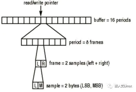
Audio frame summary
Period: the interval between hardware interrupts. It represents the input delay.
There is a pointer in the sound card interface to indicate the current read / write position in the sound card hardware cache. As long as the interface is running, the pointer will loop to a location in the cache.
frame size =sizeof(one sample) * nChannels
The buffer and period size configured in alsa are stored as frames in runtime.
Period ﹣ bytes = PCM ﹣ format ﹣ to ﹣ bits is used to calculate how many bits a frame has. It is often used in practical application
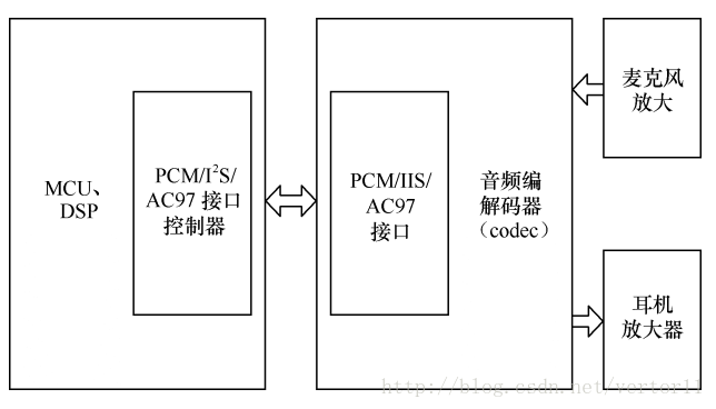
Embedded hardware level
Circuit composition
Simple process:
MIC collects natural sound and converts it into analog electrical signal, amplifies the signal amplitude by operation and amplification circuit, and then converts it into digital signal by ADC, (audio coding can be done, such as mp3), (audio decoding can be done), (analog signal can be converted by DAC) (or pulse width modulation PWM can be used to digitally code the level of analog signal), and The power amplifier is amplified and then output to the horn
See what scheme, if it involves more complex calculation, the calculation power of MCU is far from enough, it must be embedded hardware, which involves the development of system level. If it's just simple audio processing, it's OK (such as MP3 rhythm color lamp recording and playing, etc.)
Other options:
Using language integrated chips such as: ISD2560, ISD2560 adopts multi-level direct analog storage technology, which can reproduce voice, music, tone and effect sound in a very real and natural way, recording time is 60s, and can record and play 100000 times repeatedly.
2 PWM+SPI PWM analog clock timing, SPI transmission data, PCM coding, and then connected to amplifier + horn;
(the software is very simple, just throw the sampling value of wave file into pwm. Of course, the pwm signal generally needs to be added with filter circuit to send to power amplifier and horn. Generally, 16kbps sampling rate is adopted, and the filter circuit will be simple.)
3 DAC + amplifier + speaker, the general voice chip is made in this way, but it should be a special DAC voice chip;
4 IIS + voice decoding chip
These bus protocols, such as I2C SPI, are used to connect peripheral integrated circuits
In fact, the so-called audio encoder and decoder. In fact, the algorithm is compressed or decompressed by the arithmetic chip after the ordinary AD or DA
Coding scheme:
The voice quality of waveform coding is high, but the coding rate is also high (WAV);
The coding rate of parameter coding is very low, and the quality of synthesized speech is not high (MP3);
Hybrid coding uses parameter coding technology and waveform coding technology, and the coding rate and sound quality are between them.
Introduction to program terms:
Waveform code PCM
Waveform coding is based on the digital processing of speech signal waveform, trying to make the reconstructed speech signal waveform consistent with the original speech signal waveform. The advantages of waveform coding are simple implementation, good voice quality, strong adaptability, etc.; the disadvantages are that the compression degree of voice signal is not very high, and the realized code rate is relatively high. Pulse code modulation (PCM) is a common method of waveform compression and coding
Parameter code MP3
MP3 file is actually a kind of data compressed by MP3 (dynamic image expert compression standard audio level) coding algorithm, which can not be directly sent to the power amplifier, but must be decoded to restore the original audio data before playing.
PWM principle
Code example
MCU bare board development
  1 #include <reg52.h>
  2 #include <intrins.h>
  3 #define uchar unsigned char
  4 #define uint  unsigned int
  5 //Recording and playback keys IO Definition of mouth:
  6 sbit   AN=P2^6;//Playback key control interface
  7 sbit    set_key=P2^7;//Recording key control port
  8 // ISD4004 Definition of control port:
  9 sbit SS  =P1^0;     //4004 Chip selection
 10 sbit MOSI=P1^1;     //4004 data input
 11 sbit MISO=P1^2;     //4004 data output
 12 sbit SCLK=P1^3;     //ISD4004 Clock
 13 sbit INT =P1^4;     //4004 interrupt
 14 sbit STOP=P3^4;     //4004 reset
 15 sbit LED1 =P1^6;    //Recording indicator
 16 //===============================LCD1602 Interface definition=====================
 17 /*-----------------------------------------------------
 18        |DB0-----P2.0 | DB4-----P2.4 | RW-------P0.1    |
 19        |DB1-----P2.1 | DB5-----P2.5 | RS-------P0.2    |
 20        |DB2-----P2.2 | DB6-----P2.6 | E--------P0.0    |
 21        |DB3-----P2.3 | DB7-----P2.7 | Note that P0.0 to P0.2 need to be connected with pull-up resistance
 22     ---------------------------------------------------
 23 =============================================================*/
 24 #define LCM_Data     P0    //LCD1602 data interface
 25 sbit    LCM_RW     = P2^3;  //Read write control input, LCD1602 The fifth foot of
 26 sbit    LCM_RS     = P2^4;  //Register selection input, LCD1602 The fourth leg of
 27 sbit    LCM_E      = P2^2;  //Enable signal input,LCD1602 The sixth foot of
 28 //***************Function declaration************************************************
 29 void    WriteDataLCM(uchar WDLCM);//LCD Module write data
 30 void    WriteCommandLCM(uchar WCLCM,BuysC); //LCD Module write instruction
 31 uchar   ReadStatusLCM(void);//read LCD Busy label of module
 32 void    DisplayOneChar(uchar X,uchar Y,uchar ASCII);//In the first place X+1 Line No Y+1 Position display one character
 33 void    LCMInit(void);
 34 void    DelayUs(uint us); //Subtle delay procedure
 35 void    DelayMs(uint Ms);//Millisecond delay program
 36 void    init_t0();//Timer 0 initialization function
 37 void    setkey_treat(void);//Recording key handler
 38 void    upkey_treat(void);//Play key handler
 39 void    display();//Display handler
 40 void    isd_setrec(uchar adl,uchar adh);//Send out setrec instructions
 41 void    isd_rec();//Send out rec instructions
 42 void    isd_stop();//stop Command (stop current operation)
 43 void    isd_powerup();//Send power on command
 44 void    isd_stopwrdn();//Send power down command
 45 void    isd_send(uchar isdx);//spi Serial transmission subroutine, 8-bit data
 46 void    isd_setplay(uchar adl,uchar adh);
 47 void    isd_play();
 48 //Some constant definitions in the program
 49 uint    time_total,st_add,end_add=0;
 50 uint    adds[25];//25 Start address temporary storage of segment voice
 51 uint    adde[25];//25 The end address of segment voice is temporary
 52 uchar   t0_crycle,count,count_flag,flag2,flag3,flag4;
 53 uchar   second_count=170,msecond_count=0;
 54 //second_count Is the starting address of the chip recording. The starting address was originally A0,That's 160,
 55 //Let's start recording at 170.
 56 #define Busy         0x80   //For testing LCM In the status word Busy Identification
 57
 58 /*===========================================================================
 59  main program
 60 =============================================================================*/
 61 void main(void)
 62 {
 63    LED1=0;//Turn off recording indicator
 64    flag3=0;
 65    flag4=0;
 66    time_total=340;//The recording address starts from 170, and the corresponding SCM starts timing 340*0.1 second
 67    adds[0]=170;
 68    count=0;
 69    LCMInit();        //1602 initialization
 70    init_t0();//timer initiated
 71    DisplayOneChar( 0,5,'I'); //Display 000 when power on  ISD4004-X
 72    DisplayOneChar( 0,6,'S');
 73    DisplayOneChar( 0,7,'D');
 74    DisplayOneChar( 0,8,'4');
 75    DisplayOneChar( 0,9,'0');
 76    DisplayOneChar( 0,10,'0');
 77    DisplayOneChar( 0,11,'4');
 78    DisplayOneChar( 0,12,'-');
 79    DisplayOneChar( 0,13,'X');
 80    while(1)
 81    {
 82       display();//Display processing
 83       upkey_treat();//Playback key processing
 84       setkey_treat();//Recording key processing
 85    }
 86 }
 87 //*******************************************
 88 //Recording key handler
 89 //This is the program that starts recording from the specified address
 90 void setkey_treat(void)
 91 {
 92    set_key=1;//Set up IO Port 1, ready to read in data
 93    DelayUs(1);
 94    if(set_key==0)
 95    {
 96       if(flag3==0)//The recording key and the playback key are interlocked. After recording, it is forbidden to record again. If you want to record again, you need to reset the MCU and start recording again
 97       {
 98         if(count==0)//Determine whether it is the first time to press the recording key since power on or reset
 99         {
100            st_add=170;
101         }
102         else
103         {
104           st_add=end_add+3;
105         }//3 addresses per language interval
106         adds[count]=st_add;//The starting address of each voice segment is temporary
107         if(count>=25)//When judging the number of voice segments, it is more than 25 segments, because of the relationship between SCM memory?
108        //This program only records 25 segments. If you want to record more voice, you can change it to non searchable
109         {//If more than 25 segments, overwrite the previous voice and start recording again
110            count=0;
111            st_add=170;
112            time_total=340;
113         }
114         isd_powerup(); //AN Key down, ISD Power on and delay 50 ms
115         isd_stopwrdn();
116         isd_powerup();
117         LED1=1;//The recording indicator is on, indicating the recording mode
118         isd_setrec(st_add&0x00ff,st_add>>8); //From the specified address
119         if(INT==1)// Determine whether the chip overflows
120         {
121             isd_rec(); //Send recording command
122         }
123         time_total=st_add*2;//Timing initial value calculation
124         TR0=1;//On timer
125         while(set_key==0);//Wait for the end of this recording
126         TR0=0;//Stop timing after recording
127         isd_stop(); //Send 4004 stop command
128         end_add=time_total/2+2;//Calculate the end address of voice
129         adde[count]=end_add;//Temporary storage of voice end address
130         LED1=0; //After recording, LED Extinguish
131         count++;//Recording segment number self adding
132         count_flag=count;//Recording segment number deposit
133         flag2=1;
134         flag4=1;//Unlock playback key
135       }
136   }
137 }
138 //=================================================
139 //Player handler
140 //It's the program to play this voice from the specified address
141 void upkey_treat(void)
142 {
143    uchar ovflog;
144    AN=1;//Prepare to read in data
145    DelayUs(1);
146    if(AN==0)//Judge whether the playback key acts
147    {
148  //    if(flag4==1)//Interlock recording key
149  //    {
150         if(flag2==1)//Judge whether it is the first playback after recording
151         {
152            count=0;//Play from segment 0
153         }
154         isd_powerup(); //AN Key down, ISD Power on and delay 50 ms
155         isd_stopwrdn();
156         isd_powerup();
157         //170 184 196 211
158    //     st_add=adds[count];//Send the starting address of the current voice
159         st_add=211;//Send the starting address of the current voice
160         isd_setplay(st_add&0x00ff,st_add>>8); //Send out setplay Command, play from specified address
161         isd_play(); //Send playback command
162         DelayUs(20);
163         while(INT==1); //Waiting for the sound to finish EOM Interrupt signal
164         isd_stop(); //Play finished, send stop instructions
165         while(AN==0); //
166         isd_stop();
167         count++;//Speech segment number self adding
168         flag2=0;
169         flag3=1;
170         if(count>=count_flag)//If you press the add key after playing to the last paragraph, play again from the first paragraph
171         {
172              count=0;
173         }
174
175  //     }
176    }
177 }
178 //************************************************?
179 //Send out rec instructions
180 void isd_rec()
181 {
182     isd_send(0xb0);
183     SS=1;
184 }
185 //****************************************
186 //Send out setrec instructions
187 void isd_setrec(unsigned char adl,unsigned char adh)
188 {
189     DelayMs(1);
190     isd_send(adl); //Send playback start address low
191     DelayUs(2);
192     isd_send(adh); //Start address high
193     DelayUs(2);
194     isd_send(0xa0); //Send out setplay Instruction byte
195     SS=1;
196 }
197 //=============================================================================
198 //**********************************************
199 //Timer 0 interrupt program
200 void timer0() interrupt 1
201 {
202     TH0=(65536-50000)/256;
203     TL0=(65536-50000)%256;
204     t0_crycle++;
205     if(t0_crycle==2)// 0.1 second
206     {
207       t0_crycle=0;
208       time_total++;
209       msecond_count++;
210       if(msecond_count==10)//1 second
211       {
212         msecond_count=0;
213         second_count++;
214         if(second_count==60)
215         {
216           second_count=0;
217         }
218       }
219       if(time_total==4800)time_total=0;
220     }
221 }
222 //********************************************************************************************
223 //Timer 0 initialization function
224 void init_t0()
225 {
226     TMOD=0x01;//Set timer working mode 1, timer timing 50ms
227     TH0=(65536-50000)/256;
228     TL0=(65536-50000)%256;
229     EA=1;//Total interruption
230     ET0=1;//Allow timer 0 interrupt
231     t0_crycle=0;//Timer interrupt count unit
232 }
233 //******************************************
234 //Display handler
235 void display()
236 {
237         uchar x;
238         if(flag3==1||flag4==1)//Judge whether there is any recording or playback
239         {
240           x=count-1;
241           if(x==255){x=count_flag-1;}
242         }
243         DisplayOneChar( 0,0,x/100+0x30);    //What is the current voice
244         DisplayOneChar( 0,1,x/10%10+0x30);
245         DisplayOneChar( 0,2,x%10+0x30);
246         if(flag3==0)//Show the starting and ending address of this voice while recording
247         {
248            DisplayOneChar( 1,0,st_add/1000+0x30);//Calculate and display kilobits
249            DisplayOneChar( 1,1,st_add/100%10+0x30);
250            DisplayOneChar( 1,2,st_add/10%10+0x30);
251            DisplayOneChar( 1,3,st_add%10+0x30);
252            DisplayOneChar( 1,4,'-');
253            DisplayOneChar( 1,5,'-');
254            DisplayOneChar( 1,6,end_add/1000+0x30);
255            DisplayOneChar( 1,7,end_add/100%10+0x30);
256            DisplayOneChar( 1,8,end_add/10%10+0x30);
257            DisplayOneChar( 1,9,end_add%10+0x30);
258         }
259         if(flag4==1)//Show the starting and ending address of this voice during playback
260         {
261            DisplayOneChar( 1,0,adds[x]/1000+0x30);
262            DisplayOneChar( 1,1,adds[x]/100%10+0x30);
263            DisplayOneChar( 1,2,adds[x]/10%10+0x30);
264            DisplayOneChar( 1,3,adds[x]%10+0x30);
265            DisplayOneChar( 1,4,'-');
266            DisplayOneChar( 1,5,'-');
267            DisplayOneChar( 1,6,adde[x]/1000+0x30);
268            DisplayOneChar( 1,7,adde[x]/100%10+0x30);
269            DisplayOneChar( 1,8,adde[x]/10%10+0x30);
270            DisplayOneChar( 1,9,adde[x]%10+0x30);
271         }
272 }
273 //======================================================================
274 // LCM initialization
275 //======================================================================
276 void LCMInit(void)
277 {
278  LCM_Data = 0;
279  WriteCommandLCM(0x38,0); //Three time display mode setting, no busy signal detection
280  DelayMs(5);
281  WriteCommandLCM(0x38,0);
282  DelayMs(5);
283  WriteCommandLCM(0x38,0);
284  DelayMs(5);
285  WriteCommandLCM(0x38,1); //Display mode settings,Start to ask to detect busy signal every time
286  WriteCommandLCM(0x08,1); //Turn off display
287  WriteCommandLCM(0x01,1); //Clear screen
288  WriteCommandLCM(0x06,1); // Display cursor movement settings
289  WriteCommandLCM(0x0C,1); // Display on and cursor settings
290  DelayMs(100);
291 }
292 //*=====================================================================
293 // Write data function: E =High pulse RS=1 RW=0
294 //======================================================================
295 void WriteDataLCM(uchar WDLCM)
296 {
297  ReadStatusLCM(); //Test busy
298  LCM_Data = WDLCM;
299  LCM_RS = 1;
300  LCM_RW = 0;
301  LCM_E = 0; //If the crystal speed is too high, a small delay can be added after this
302  LCM_E = 0; //delayed
303  LCM_E = 1;
304 }
305 //*====================================================================
306  // Write instruction function: E=High pulse RS=0 RW=0
307 //======================================================================
308 void WriteCommandLCM(unsigned char WCLCM,BuysC) //BuysC Ignore busy detection for 0
309 {
310  if (BuysC) ReadStatusLCM(); //Test busy as needed
311  LCM_Data = WCLCM;
312  LCM_RS = 0;
313  LCM_RW = 0;
314  LCM_E = 0;
315  LCM_E = 0;
316  LCM_E = 1;
317 }
318 //*====================================================================
319 //  Must be detected before normal read and write operation LCD Controller status:E=1 RS=0 RW=1;
320 //  DB7: 0 LCD Controller idle, 1 LCD The controller is busy.
321  // Read status
322 //======================================================================
323 unsigned char ReadStatusLCM(void)
324 {
325  LCM_Data = 0xFF;
326  LCM_RS = 0;
327  LCM_RW = 1;
328  LCM_E = 0;
329  LCM_E = 0;
330  LCM_E = 1;
331  while (LCM_Data & Busy); //Detect busy signal
332  return(LCM_Data);
333 }
334 //======================================================================
335 //Function:     Display one character at 1602:First line position 0~15,Line 2 16~31
336 //explain:     The first X That's ok,The first y Column note:String cannot be longer than 16 characters
337 //======================================================================
338 void DisplayOneChar( unsigned char X, unsigned char Y, unsigned char ASCII)
339 {
340  X &= 0x1;
341  Y &= 0xF; //limit Y Not more than 15, X Cannot be greater than 1
342  if (X) Y |= 0x40; //Address code when the second line is to be displayed+0x40;
343  Y |= 0x80; // Work out the instruction code
344  WriteCommandLCM(Y, 0); //No busy signal is detected here, send address code
345  WriteDataLCM(ASCII);
346 }
347 //======================================================================
348 //spi Serial transmission subroutine, 8-bit data
349 void isd_send(uchar isdx)
350 {
351     uchar isx_counter;
352     SS=0;//ss=0,open spi Communication terminal
353     SCLK=0;
354     for(isx_counter=0;isx_counter<8;isx_counter++)//Send low first, then high, and send in turn.
355     {
356         if((isdx&0x01)==1)
357             MOSI=1;
358         else
359             MOSI=0;
360             isdx=isdx>>1;
361             SCLK=1;
362             DelayUs(2);
363             SCLK=0;
364             DelayUs(2);
365     }
366 }
367 //======================================================================
368 //stop Command (stop current operation)
369 void isd_stop()//
370 {
371     DelayUs(10);
372     isd_send(0x30);
373     SS=1;
374     DelayMs(50);
375 }
376 //======================================================================
377 //Send power on command
378 void isd_powerup()//
379 {
380     DelayUs(10);
381     SS=0;
382     isd_send(0x20);
383     SS=1;
384     DelayMs(50);
385 }
386 //======================================================================
387 //Send power down command
388 void isd_stopwrdn()//
389 {
390     DelayUs(10);
391     isd_send(0x10);
392     SS=1;
393     DelayMs(50);
394 }
395
396 void isd_play()//Send out play instructions
397 {
398     isd_send(0xf0);
399     SS=1;
400 }
401 void isd_setplay(uchar adl,uchar adh)//Send out setplay instructions
402 {
403     DelayMs(1);
404     isd_send(adl); //Send playback start address low
405     DelayUs(2);
406     isd_send(adh); //Start address high
407     DelayUs(2);
408     isd_send(0xe0); //Send out setplay Instruction byte
409     SS=1;
410 }
411 void DelayUs(uint us)
412 {
413     while(us--);
414 }
415 //====================================================================
416 // Set delay time:x*1ms
417 //====================================================================
418 void DelayMs(uint Ms)
419 {
420   uint i,TempCyc;
421   for(i=0;i<Ms;i++)
422   {
423     TempCyc = 250;
424     while(TempCyc--);
425   }
426 }
427