Objective: to solve the problem of inaccurate software delay by using timer.
Several methods to realize timing function:
1. Software timing: software timing does not take up hardware resources, but takes up CPU time, reducing CPU utilization.
2. Time base circuit timing: for example, 555 circuit.
3. Using programmable chip timing: the timing value and timing range of this timing chip are easy to be determined and modified by software. At this time, the chip timing function is strong and flexible.
4. Single chip timer, extended timer chip. (the chip with timer integrated inside the single chip computer)
IAP15F2K60S2: timer 0, 1 and 2 are consistent with 89C52 series single chip microcomputer
IAP15W4K58S4: timer 0, 1, 2, 3, 4
STC8A8K64S4A2: timer 0, 1, 2, 3, 4
Timer / counter is actually a 16 bit counter added with 1, which consists of two registers: high 8-bit and low 8-bit.
Use of timers / counters:
1. Configure aux r auxiliary register; 2. Configure TMOD working mode register; 3. Load count initial value, high octet is loaded at TH0, low octet is loaded at TL0; 4. Configure TCON control register; 5. Configure interrupt allow register IE
For details, please refer to the instruction manual:
Aux r auxiliary register: it is used to check whether it is compatible with traditional 8051 single chip microcomputer and can not be addressed.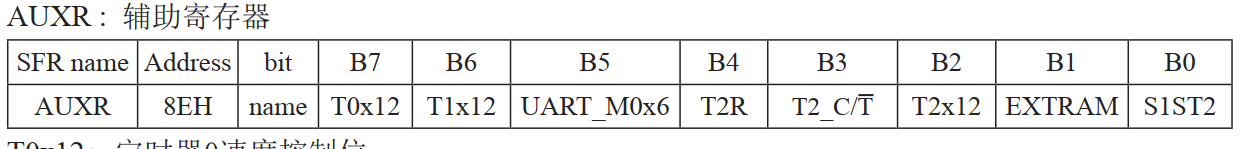
TMOD working mode register: determines the working mode and function. The low four bits are used for T0, the high four bits are used for T1, and cannot be addressed.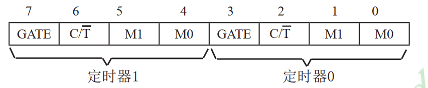
Counter / Timer - count (timing) register: used for counting or timing of counter / timer. Timer 0: TL0 timer low octet register, TH0 timer 0 high octet register.
Mode 0: 16 bit auto reload mode
Timer mode: N=t/Tcy (Tcy is the machine cycle) (t is the required timing time)
The formula of counting initial value is: the 16th power of X=2 (i.e. 65536) - N
That is to say, the initial count value of each timer is x, counting from X to top in turn, until the count overflows when it reaches 65536, sending information to the CPU, finishing the timing, reloading the initial count value x to count again. Where the value of X is binary, loaded in TH0 (high octet) and TL0 (low octet).
TCON control register: it controls the start and stop of T0 and T1, and sets overflow flag, which is bit addressable.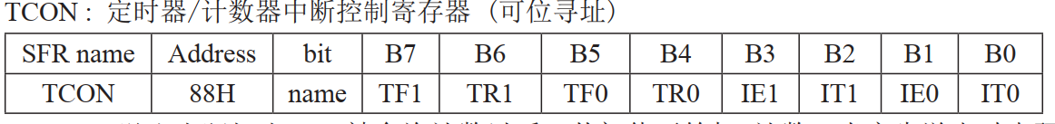
IE interrupt allow register: allow interrupt or not, bit addressable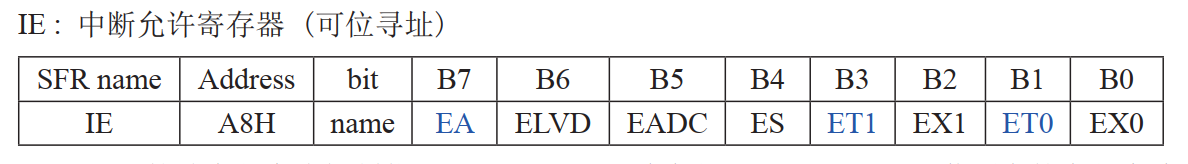
The period of crystal oscillation of 15 series MCU is equal to that of machine
Timer configuration method:
1. Configure according to the manual, and pay attention to distinguish the bitable and non bitable registers.
2. Use the downloader to generate, as shown in the following figure: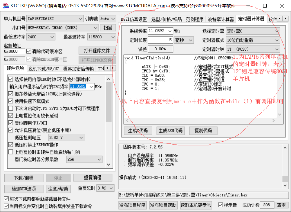
Note: no matter which method is used, the interrupt allow register EA=1;ET0=1 must be configured;
The example procedure is as follows:
1. Use timer 0 (take 5ms as an example, configure according to the instructions), LED1 1s flashes once
#include<STC15F2K60S2.H>

unsigned char tt=0;

void main(void)
{
	P2=0XA0;P0=0X00;P2=0X80;P0=0XFF;	//Initializer
	//The following configuration procedure is carried out according to the instructions, and the timing time is 5ms as an example
	AUXR=0X80;		//According to the manual, timer 0 controls position 1 at a speed of 12 times that of traditional 8051 without frequency division
	TMOD=0XF0;		//Select use timer 0,16 bit auto reload mode
	TH0=0X28;			//The high octet of the binary number corresponding to the initial value of the load count
	TL0=0x00;			//The lower octet of the binary number corresponding to the initial value of the load count
	TF0=0;				//The overflow interrupt flag bit of the reset timer 0 is usually reset before use
	TR0=1;				//Timer 0 starts counting, and T0 counting is forbidden if TR0=0

	EA=1;ET0=1;		//Allowed interruption

	while(1)
	{
	}
}

void Timer0(void) interrupt 1			//Timer 0 must use interrupt 1
{
	tt++;
	if(tt==200)							//200 times, 1 s
	{
		tt=0;
		P00=~P00;
	}
}
2. Use timer 0 (take 5ms as an example, use downloader configuration) digital tube timing 1 s change 1 time)
#include<STC15F2K60S2.H>
unsigned char tt=0;
unsigned char num=0;
unsigned char tab[]={0XC0,0XF9,0XA4,0XB0,0X99,0X92,0X82,0XF8,0X80,0X90,0X88,0X83,0XC6,0XA1,0X86,0X8E};

void Timer0Init(void);

void main(void)
{
	P2=0XA0;P0=0X00;P2=0X80;P0=0XFF;   //Initializer
	P2=0XC0;P0=0X01;P2=0XFF;P0=0XFF;   //Nixie tube initialization program, open the first nixie tube
	Timer0Init();
	EA=1;ET0=1;

	while(1)
	{
	}
}
//The following function is generated by the downloader, which only needs to be called before
void Timer0Init(void)		//5ms @ 11.0592MHz
{
	AUXR |= 0x80;		//Timer clock 1T mode
	TMOD &= 0xF0;		//Set timer mode
	TL0 = 0x00;		//Set initial value of timing
	TH0 = 0x28;		//Set initial value of timing
	TF0 = 0;		//Clear TF0 flag
	TR0 = 1;		//Timer 0 starts
}

void Timer0(void) interrupt 1
{
	tt++;
	if(tt==200)
	{
		tt=0;
		P0=tab[num];
		num++;
		if(num==16)num=0;				//When num=16, it is out of the range of the array, reset to 0
	}
}
The inside of the while loop in both programs is empty, and the program only executes the commands in interrupt 1. Timer 0 corresponds to interrupt 1.

