Hello, I'm ruffian Heng, a serious technical ruffian. Today, ruffian Heng introduced the system interrupt delay time of i.MXRT1xxx.
In Introduction to Cortex-M system interrupt delay and its measurement method In this paper, PI Ziheng introduced the basic concept of Cortex-M interrupt delay and a method to measure the interrupt delay time with GPIO module. Today, we will measure the interrupt delay on i.MXRT1xxx series chips with this method:
1, Official indicators
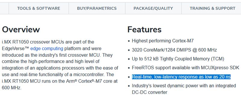
At present, there are many models of NXP i.MXRT1xxx series, which are based on Cortex-M7 core, and the main frequency ranges from 500MHz to 1GHz. Take the first model i.MXRT1050 of the series for example Official homepage It can be seen that its nominal interrupt delay time is as low as 20ns.
In Cortex-M system interrupt delay In the first section of this article, we know that the standard interrupt delay of Cortex-M7 is 12-14 core clock cycles, and the main frequency of i.MXRT1050 is 600MHz. Theoretical calculation shows that (1s / 600MHz) * 12 = 20ns, so the 20ns interrupt delay on i.MXRT1050 conforms to the ARM standard.
2, Test code
Now let's measure it on the chip. Ruffian Heng has tested the five models i.MXRT1011/1021/1052/1062/1176. The test code can be based on their respective SDK packages.
Take i.MXRT1052 as an example, select \ SDK_2.10.0_EVKB-IMXRT1050\boards\evkbimxrt1050\driver_examples\gpio\input_interrupt routine is the template (pay attention to select debug build, that is, the code is linked in TCM to meet the test requirements of zero waiting memory). Press Cortex-M system interrupt delay The design idea of the second section of this paper is to modify the main function as follows (for reference to the use of GPIO interrupt) Taking the GPIO module of i.MXRT1xxx as an example, talk about the standard flow of interrupt handler (IRQHandler) (text):
- Note1: for the accuracy of the results, ruffian Heng tested several different types of GPIO interrupts at the same time, because some i.MXRT models contain ordinary GPIO and HSGPIO, and some GPIO events can trigger Combined interrupts or independent interrupts.
- Note2: the type of GPIO used for the output signal is not important for this test. Whether ordinary GPIO or HSGPIO is selected to flip, its flip time will not affect the final test result.
uint32_t s_pin_low  = 0x000000;
uint32_t s_pin_high = 0x800000;

////////////////////////////////////////////////////////////////////////////////
// User Button SW8 - Pin4 in RT1050-EVKB
void GPIO5_Combined_0_15_IRQHandler(void)
{
    GPIO2->DR = s_pin_low;
    GPIO2->DR = s_pin_high;
    GPIO_PortClearInterruptFlags(GPIO5, 1U << 0);
    __DSB();
}

void init_gpio5_0(void)
{
    gpio_pin_config_t din_config = {kGPIO_DigitalInput, 0, kGPIO_IntFallingEdge};
    IOMUXC_SetPinMux(IOMUXC_SNVS_WAKEUP_GPIO5_IO00, 0U);
    GPIO_PinInit(GPIO5, 0, &din_config);
    NVIC_EnableIRQ(GPIO5_Combined_0_15_IRQn);
    GPIO_PortEnableInterrupts(GPIO5, 1U << 0);
}

////////////////////////////////////////////////////////////////////////////////
// Arduino Interface, J24-2 in RT1050-EVKB
void GPIO1_Combined_0_15_IRQHandler(void)
{
    GPIO2->DR = s_pin_low;
    GPIO2->DR = s_pin_high;
    GPIO_PortClearInterruptFlags(GPIO1, 1U << 2);
    __DSB();
}

void GPIO1_INT2_IRQHandler(void)
{
    GPIO2->DR = s_pin_low;
    GPIO2->DR = s_pin_high;
    GPIO_PortClearInterruptFlags(GPIO1, 1U << 2);
    __DSB();
}

void init_gpio1_2(void)
{
    gpio_pin_config_t din_config = {kGPIO_DigitalInput, 0, kGPIO_IntFallingEdge};
    IOMUXC_SetPinMux(IOMUXC_GPIO_AD_B0_02_GPIO1_IO02, 0U);
    GPIO_PinInit(GPIO1, 2, &din_config);
    NVIC_EnableIRQ(GPIO1_Combined_0_15_IRQn);
    //NVIC_EnableIRQ(GPIO1_INT2_IRQn);
    GPIO_PortEnableInterrupts(GPIO1, 1U << 2);
}

////////////////////////////////////////////////////////////////////////////////
// TP26
void init_gpio2_23(void)
{
    gpio_pin_config_t dout_config = {kGPIO_DigitalOutput, 0, kGPIO_NoIntmode};
    IOMUXC_SetPinMux(IOMUXC_GPIO_B1_07_GPIO2_IO23, 0U);
    IOMUXC_SetPinConfig(IOMUXC_GPIO_B1_07_GPIO2_IO23, 0x70F9U);
    GPIO_PinInit(GPIO2, 23, &dout_config);
    GPIO2->DR |= 0x800000;
}

int main(void)
{
    BOARD_ConfigMPU();
    BOARD_InitBootClocks();
    CLOCK_EnableClock(kCLOCK_Iomuxc);
    CLOCK_EnableClock(kCLOCK_IomuxcSnvs);

    init_gpio5_0();
    init_gpio1_2();
    init_gpio2_23();

    while (1);
}
3, Test results
Now let's look at the detailed test results of five i.MXRT models. According to the test results, we draw the following conclusions:
- Conclusion 1: for different types of GPIO (ordinary GPIO/HSGPIO) or different types of GPIO interrupts (Combined / independent), the interrupt delay results are almost the same (except i.MXRT1170).
- Conclusion 2: the GPIO interrupt delay measured on i.MXRT1020/1050 is close to the ARM standard value, but the GPIO interrupt delay measured on i.MXRT1010/1060/1170 is greater than the ARM standard value (it is speculated that the delay caused by the GPIO module design is large, not the kernel itself).
- Conclusion 3: the GPIO interrupt delay measured by this method is not a fixed value, and there are fluctuations of about 3 kernel clock cycles (observed by multiple measurements), which may be due to the difference in synchronization timing between PAD signal jump and NVIC IRQ signal setting.
3.1 measured i.MXRT1011
| System clock configuration | PAD | GPIO | IRQ | t1 | t2 | td | Interrupt delay clocks |
|---|---|---|---|---|---|---|---|
| Core: 500MHz IPG: 125MHz |
GPIO_01 | GPIO1[1] | GPIO1_Combined_0_15_IRQn | 74 - 78ns | 33ns | 41 - 45ns | 20 - 23 cycles |
| GPIO2[1] | GPIO2_Combined_0_15_IRQn | ||||||
| GPIO_SD_05 | GPIO2[5] |
3.2 measured i.MXRT102x

| System clock configuration | PAD | GPIO | IRQ | t1 | t2 | td | Interrupt delay clocks |
|---|---|---|---|---|---|---|---|
| Core: 500MHz IPG: 125MHz |
GPIO_AD_B0_06 | GPIO1[6] | GPIO1_Combined_0_15_IRQn | 92 - 96ns | 64ns | 28 - 32ns | 14 - 16 cycles |
| GPIO1_INT6_IRQn | |||||||
| SNVS_WAKEUP | GPIO5[0] | GPIO5_Combined_0_15_IRQn |
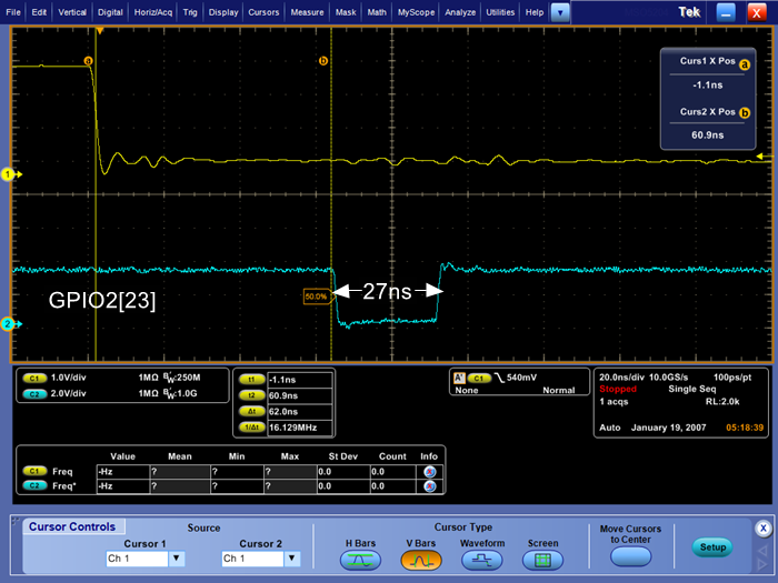
3.3 measured i.MXRT105x

| System clock configuration | PAD | GPIO | IRQ | t1 | t2 | td | Interrupt delay clocks |
|---|---|---|---|---|---|---|---|
| Core: 600MHz IPG: 150MHz |
GPIO_AD_B0_02 | GPIO1[2] | GPIO1_Combined_0_15_IRQn | 78 - 82ns | 54ns | 24 - 28ns | 14 - 17 cycles |
| GPIO1_INT2_IRQn | |||||||
| SNVS_WAKEUP | GPIO5[0] | GPIO5_Combined_0_15_IRQn |
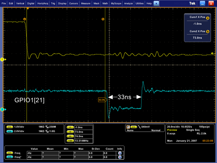
3.4 measured i.MXRT106x
| System clock configuration | PAD | GPIO | IRQ | t1 | t2 | td | Interrupt delay clocks |
|---|---|---|---|---|---|---|---|
| Core: 600MHz IPG: 150MHz |
GPIO_AD_B0_02 | GPIO1[2] | GPIO1_Combined_0_15_IRQn | 62 - 66ns | 27ns | 35 - 39ns | 21 - 24 cycles |
| GPIO1_INT2_IRQn | |||||||
| GPIO6[2] | GPIO6_7_8_9_IRQn | ||||||
| SNVS_WAKEUP | GPIO5[0] | GPIO5_Combined_0_15_IRQn |
3.5 measured i.MXRT117x

| System clock configuration | PAD | GPIO | IRQ | t1 | t2 | td | Interrupt delay clocks |
|---|---|---|---|---|---|---|---|
| Core: 996MHz BUS: 240MHz |
GPIO_AD_01 | GPIO2[31] | GPIO2_Combined_16_31_IRQn | 52 - 54ns | 29ns | 23 - 25ns | 23 - 25 cycles |
| CM7_GPIO2[31] | CM7_GPIO2_3_IRQn | ||||||
| WAKEUP_DIG | GPIO13[0] | GPIO13_Combined_0_31_IRQn | 47 - 50ns | 18 - 21ns | 18 - 21 cycles |
So far, i.MXRT1xxx's system interrupt delay time ruffian Heng has been introduced. Where is the applause~~~
Welcome to subscribe
The article will be published to me at the same time Blog Park home page,CSDN home page,Zhihu home page,WeChat official account On the platform.
Wechat search "ruffian Heng embedded" or scan the QR code below, you can see it for the first time on your mobile phone.
