We usually use various types of chips to do some projects. At this time, among different chips (due to different flash and io ports), it is the most troublesome process to transplant some of our original API s. The following are some of my experiences in porting OLED s to STM32F103C6T6 (the question is that C6T6 is cheap).
0.96-inch oled has many communication modes
IIC (4-pin OLED)
SCL and SDA adopt IIC communication mode
3-wire SPI (6-pin OLED)
D0 3-wire ISP interface mode: clock line (CLK)
D1 3-wire ISP interface mode: serial data line (MOSI)
DC Command / data flag bit A1
4-wire SPI(7-pin OLED)
D0 4-wire ISP interface mode: clock line (CLK)
D1 4-wire ISP interface mode: serial data line (MOSI)
DC Command / data flag bit A1
CS OLED chip selection
Introduction: SPI is divided into 4-wire and 3-wire interfaces, including SCLK, SDO, SDI and SS; 3-wire interface: including SCLK, SDA and SS. Therefore, the difference between 3-wire and 4-wire is that the 4-wire interface can realize master in and master out. But the third line only has master out. Whether it is 3-wire or 4-wire, SS is a must. The master can connect multiple salve s using different SS signals
The difference between four wire SPI and three wire SPI is a chip select signal line (CS). The chip select signal pin is required only when one SPI host needs to communicate with multiple slave devices. Therefore, when we use software to simulate SPI to drive an OLED, CS can not be connected.
Moreover, there is a common feature above, that is, there is no MISO (Master Input Slave Output). This is also well understood. After all, our master chip does not need to read the content of OLED, but only needs to write data.
Well, now that we have solved some fundamental problems, the next step is practical operation.
Among the most widely sold seven legged OLEDs on the market is Jingyuan electronics, and his routines are relatively widespread.
His routines are based on software simulation to control OLED. In fact, it will be very convenient for us to transplant, so we don't have to worry about the IO port.
The code simulated by 7-pin SPI software is pasted below
oled.c
#include "oled.h"
//#include "stdlib.h"
#include "oledfont.h"
#include "delay.h"
//OLED video memory
//The storage format is as follows
//[0]0 1 2 3 ... 127
//[1]0 1 2 3 ... 127
//[2]0 1 2 3 ... 127
//[3]0 1 2 3 ... 127
//[4]0 1 2 3 ... 127
//[5]0 1 2 3 ... 127
//[6]0 1 2 3 ... 127
//[7]0 1 2 3 ... 127

#if OLED_MODE==1
//Write a byte to SSD1106.
//dat: data / command to write
//cmd: data / command flag 0, indicating command; 1. Represents data;
void OLED_WR_Byte(u8 dat,u8 cmd)
{
	DATAOUT(dat);
	if(cmd)
	  OLED_DC_Set();
	else
	  OLED_DC_Clr();
	OLED_CS_Clr();
	OLED_WR_Clr();
	OLED_WR_Set();
	OLED_CS_Set();
	OLED_DC_Set();
}
#else
//Write a byte to SSD1106.
//dat: data / command to write
//cmd: data / command flag 0, indicating command; 1. Represents data;
void OLED_WR_Byte(u8 dat,u8 cmd)
{
	u8 i;
	if(cmd)
	  OLED_DC_Set();
	else
	  OLED_DC_Clr();
	OLED_CS_Clr();
	for(i=0;i<8;i++)
	{
		OLED_SCLK_Clr();
		if(dat&0x80)
		   OLED_SDIN_Set();
		else
		   OLED_SDIN_Clr();
		OLED_SCLK_Set();
		dat<<=1;
	}
	OLED_CS_Set();
	OLED_DC_Set();
}
#endif
	void OLED_Set_Pos(unsigned char x, unsigned char y)
{
	OLED_WR_Byte(0xb0+y,OLED_CMD);
	OLED_WR_Byte(((x&0xf0)>>4)|0x10,OLED_CMD);
	OLED_WR_Byte((x&0x0f)|0x01,OLED_CMD);
}
//Turn on OLED display
void OLED_Display_On(void)
{
	OLED_WR_Byte(0X8D,OLED_CMD);  //SET DCDC command
	OLED_WR_Byte(0X14,OLED_CMD);  //DCDC ON
	OLED_WR_Byte(0XAF,OLED_CMD);  //DISPLAY ON
}
//Turn off OLED display
void OLED_Display_Off(void)
{
	OLED_WR_Byte(0X8D,OLED_CMD);  //SET DCDC command
	OLED_WR_Byte(0X10,OLED_CMD);  //DCDC OFF
	OLED_WR_Byte(0XAE,OLED_CMD);  //DISPLAY OFF
}
//Clear screen function, clear the screen, the whole screen is black! It's the same as not lit!!!
void OLED_Clear(void)
{
	u8 i,n;
	for(i=0;i<8;i++)
	{
		OLED_WR_Byte (0xb0+i,OLED_CMD);    //Set page address (0 ~ 7)
		OLED_WR_Byte (0x00,OLED_CMD);      //Set display position - column low address
		OLED_WR_Byte (0x10,OLED_CMD);      //Set display position - column height address
		for(n=0;n<128;n++)OLED_WR_Byte(0,OLED_DATA);
	} //update display
}


//Displays a character in the specified position, including some characters
//x:0~127
//y:0~63
//mode:0, negative display; 1. Normal display
//size: select font 16 / 12
void OLED_ShowChar(u8 x,u8 y,u8 chr)
{
	unsigned char c=0,i=0;
		c=chr-' ';//Get the offset value
		if(x>Max_Column-1){x=0;y=y+2;}
		if(SIZE ==16)
			{
			OLED_Set_Pos(x,y);
			for(i=0;i<8;i++)
			OLED_WR_Byte(F8X16[c*16+i],OLED_DATA);
			OLED_Set_Pos(x,y+1);
			for(i=0;i<8;i++)
			OLED_WR_Byte(F8X16[c*16+i+8],OLED_DATA);
			}
			else {
				OLED_Set_Pos(x,y+1);
				for(i=0;i<6;i++)
				OLED_WR_Byte(F6x8[c][i],OLED_DATA);

			}
}
//m^n function
u32 oled_pow(u8 m,u8 n)
{
	u32 result=1;
	while(n--)result*=m;
	return result;
}
//Display 2 numbers
//x. Y: starting point coordinates
//len: number of digits
//Size: font size
//Mode: mode 	 0, filling mode; 1. Superposition mode
//num: value (0 ~ 4294967295);
void OLED_ShowNum(u8 x,u8 y,u32 num,u8 len,u8 size)
{
	u8 t,temp;
	u8 enshow=0;
	for(t=0;t<len;t++)
	{
		temp=(num/oled_pow(10,len-t-1))%10;
		if(enshow==0&&t<(len-1))
		{
			if(temp==0)
			{
				OLED_ShowChar(x+(size/2)*t,y,' ');
				continue;
			}else enshow=1;

		}
	 	OLED_ShowChar(x+(size/2)*t,y,temp+'0');
	}
}
//Displays a character string
void OLED_ShowString(u8 x,u8 y,u8 *chr)
{
	unsigned char j=0;
	while (chr[j]!='\0')
	{		OLED_ShowChar(x,y,chr[j]);
			x+=8;
		if(x>120){x=0;y+=2;}
			j++;
	}
}
//Display Chinese characters
void OLED_ShowCHinese(u8 x,u8 y,u8 no)
{
	u8 t,adder=0;
	OLED_Set_Pos(x,y);
    for(t=0;t<16;t++)
		{
				OLED_WR_Byte(Hzk[2*no][t],OLED_DATA);
				adder+=1;
     }
		OLED_Set_Pos(x,y+1);
    for(t=0;t<16;t++)
			{
				OLED_WR_Byte(Hzk[2*no+1][t],OLED_DATA);
				adder+=1;
      }
}
/***********Function Description: display BMP picture 128 × 64 starting point coordinates (x, y), the range of X is 0 ~ 127, and Y is the range of page 0 ~ 7*****************/
void OLED_DrawBMP(unsigned char x0, unsigned char y0,unsigned char x1, unsigned char y1,unsigned char BMP[])
{
 unsigned int j=0;
 unsigned char x,y;

  if(y1%8==0) y=y1/8;
  else y=y1/8+1;
	for(y=y0;y<y1;y++)
	{
		OLED_Set_Pos(x0,y);
    for(x=x0;x<x1;x++)
	    {
	    	OLED_WR_Byte(BMP[j++],OLED_DATA);
	    }
	}
}


//Initialize SSD1306
void OLED_Init(void)
{


 	GPIO_InitTypeDef  GPIO_InitStructure;

 	RCC_APB2PeriphClockCmd(RCC_APB2Periph_GPIOA, ENABLE);	 //Enable port A clock
	GPIO_InitStructure.GPIO_Pin = GPIO_Pin_4|GPIO_Pin_5|GPIO_Pin_7;
 	GPIO_InitStructure.GPIO_Mode = GPIO_Mode_Out_PP; 		 //Push pull output
	GPIO_InitStructure.GPIO_Speed = GPIO_Speed_50MHz;//Speed 50MHz
 	GPIO_Init(GPIOA, &GPIO_InitStructure);	  //Initialize GPIOD3,6
 	GPIO_SetBits(GPIOA,GPIO_Pin_5|GPIO_Pin_7|GPIO_Pin_4);

	RCC_APB2PeriphClockCmd(RCC_APB2Periph_GPIOB, ENABLE);	 //Enable port A clock
	GPIO_InitStructure.GPIO_Pin = GPIO_Pin_0|GPIO_Pin_1|GPIO_Pin_8;
 	GPIO_InitStructure.GPIO_Mode = GPIO_Mode_Out_PP; 		 //Push pull output
	GPIO_InitStructure.GPIO_Speed = GPIO_Speed_50MHz;//Speed 50MHz
 	GPIO_Init(GPIOB, &GPIO_InitStructure);	  //Initialize GPIOD3,6
 	GPIO_SetBits(GPIOB,GPIO_Pin_0|GPIO_Pin_1|GPIO_Pin_8);


  OLED_RST_Set();
	delay_ms(100);
	OLED_RST_Clr();
	delay_ms(200);
	OLED_RST_Set();

	OLED_WR_Byte(0xAE,OLED_CMD);//--turn off oled panel
	OLED_WR_Byte(0x00,OLED_CMD);//---set low column address
	OLED_WR_Byte(0x10,OLED_CMD);//---set high column address
	OLED_WR_Byte(0x40,OLED_CMD);//--set start line address  Set Mapping RAM Display Start Line (0x00~0x3F)
	OLED_WR_Byte(0x81,OLED_CMD);//--set contrast control register
	OLED_WR_Byte(0xCF,OLED_CMD); // Set SEG Output Current Brightness
	OLED_WR_Byte(0xA1,OLED_CMD);//--Set SEG / column mapping 0xa0 left and right reverse 0xa1 normal
	OLED_WR_Byte(0xC8,OLED_CMD);//Set COM / row scan direction 0xc0 upside down 0xc8 normal
	OLED_WR_Byte(0xA6,OLED_CMD);//--set normal display
	OLED_WR_Byte(0xA8,OLED_CMD);//--set multiplex ratio(1 to 64)
	OLED_WR_Byte(0x3f,OLED_CMD);//--1/64 duty
	OLED_WR_Byte(0xD3,OLED_CMD);//-set display offset	Shift Mapping RAM Counter (0x00~0x3F)
	OLED_WR_Byte(0x00,OLED_CMD);//-not offset
	OLED_WR_Byte(0xd5,OLED_CMD);//--set display clock divide ratio/oscillator frequency
	OLED_WR_Byte(0x80,OLED_CMD);//--set divide ratio, Set Clock as 100 Frames/Sec
	OLED_WR_Byte(0xD9,OLED_CMD);//--set pre-charge period
	OLED_WR_Byte(0xF1,OLED_CMD);//Set Pre-Charge as 15 Clocks & Discharge as 1 Clock
	OLED_WR_Byte(0xDA,OLED_CMD);//--set com pins hardware configuration
	OLED_WR_Byte(0x12,OLED_CMD);
	OLED_WR_Byte(0xDB,OLED_CMD);//--set vcomh
	OLED_WR_Byte(0x40,OLED_CMD);//Set VCOM Deselect Level
	OLED_WR_Byte(0x20,OLED_CMD);//-Set Page Addressing Mode (0x00/0x01/0x02)
	OLED_WR_Byte(0x02,OLED_CMD);//
	OLED_WR_Byte(0x8D,OLED_CMD);//--set Charge Pump enable/disable
	OLED_WR_Byte(0x14,OLED_CMD);//--set(0x10) disable
	OLED_WR_Byte(0xA4,OLED_CMD);// Disable Entire Display On (0xa4/0xa5)
	OLED_WR_Byte(0xA6,OLED_CMD);// Disable Inverse Display On (0xa6/a7)
	OLED_WR_Byte(0xAF,OLED_CMD);//--turn on oled panel

	OLED_WR_Byte(0xAF,OLED_CMD); /*display ON*/
	OLED_Clear();
	OLED_Set_Pos(0,0);
}
oled.h
#ifndef __OLED_H
#define __OLED_H
#include "sys.h"
//#include "stdlib.h"
//OLED mode setting
//0:4-wire serial mode
//1: Parallel 8080 mode
#define OLED_MODE 0
#define SIZE 16
#define XLevelL		0x00
#define XLevelH		0x10
#define Max_Column	128
#define Max_Row		64
#define	Brightness	0xFF
#define X_WIDTH 	128
#define Y_WIDTH 	64

//-----------------Test LED port definition----------------
#define LED_ON GPIO_ResetBits(GPIOB,GPIO_Pin_8)//DC
#define LED_OFF GPIO_SetBits(GPIOB,GPIO_Pin_8)

//-----------------OLED port definition----------------


#define OLED_SCLK_Clr() GPIO_ResetBits(GPIOA,GPIO_Pin_5)//CLK
#define OLED_SCLK_Set() GPIO_SetBits(GPIOA,GPIO_Pin_5)

#define OLED_SDIN_Clr() GPIO_ResetBits(GPIOA,GPIO_Pin_7)//DIN
#define OLED_SDIN_Set() GPIO_SetBits(GPIOA,GPIO_Pin_7)

#define OLED_RST_Clr() GPIO_ResetBits(GPIOB,GPIO_Pin_0)//RES
#define OLED_RST_Set() GPIO_SetBits(GPIOB,GPIO_Pin_0)

#define OLED_DC_Clr() GPIO_ResetBits(GPIOB,GPIO_Pin_1)//DC
#define OLED_DC_Set() GPIO_SetBits(GPIOB,GPIO_Pin_1)

#define OLED_CS_Clr()  GPIO_ResetBits(GPIOA,GPIO_Pin_4)//CS
#define OLED_CS_Set()  GPIO_SetBits(GPIOA,GPIO_Pin_4)

#define OLED_CMD  0 	// Write command
#define OLED_DATA 1 	// Write data


//Functions for OLED control
void OLED_WR_Byte(u8 dat,u8 cmd);
void OLED_Display_On(void);
void OLED_Display_Off(void);
void OLED_Init(void);
void OLED_Clear(void);
void OLED_DrawPoint(u8 x,u8 y,u8 t);
void OLED_Fill(u8 x1,u8 y1,u8 x2,u8 y2,u8 dot);
void OLED_ShowChar(u8 x,u8 y,u8 chr);
void OLED_ShowNum(u8 x,u8 y,u32 num,u8 len,u8 size);
void OLED_ShowString(u8 x,u8 y, u8 *p);
void OLED_Set_Pos(unsigned char x, unsigned char y);
void OLED_ShowCHinese(u8 x,u8 y,u8 no);
void OLED_DrawBMP(unsigned char x0, unsigned char y0,unsigned char x1, unsigned char y1,unsigned char BMP[]);
#endif
In the oled.h file, a large number of basic operations of oled are encapsulated. In the process of transplantation, you only need to rewrite these macro definitions.
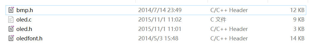
You only need to migrate these files to a new file.
Then add the oled.c file to KEIL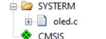
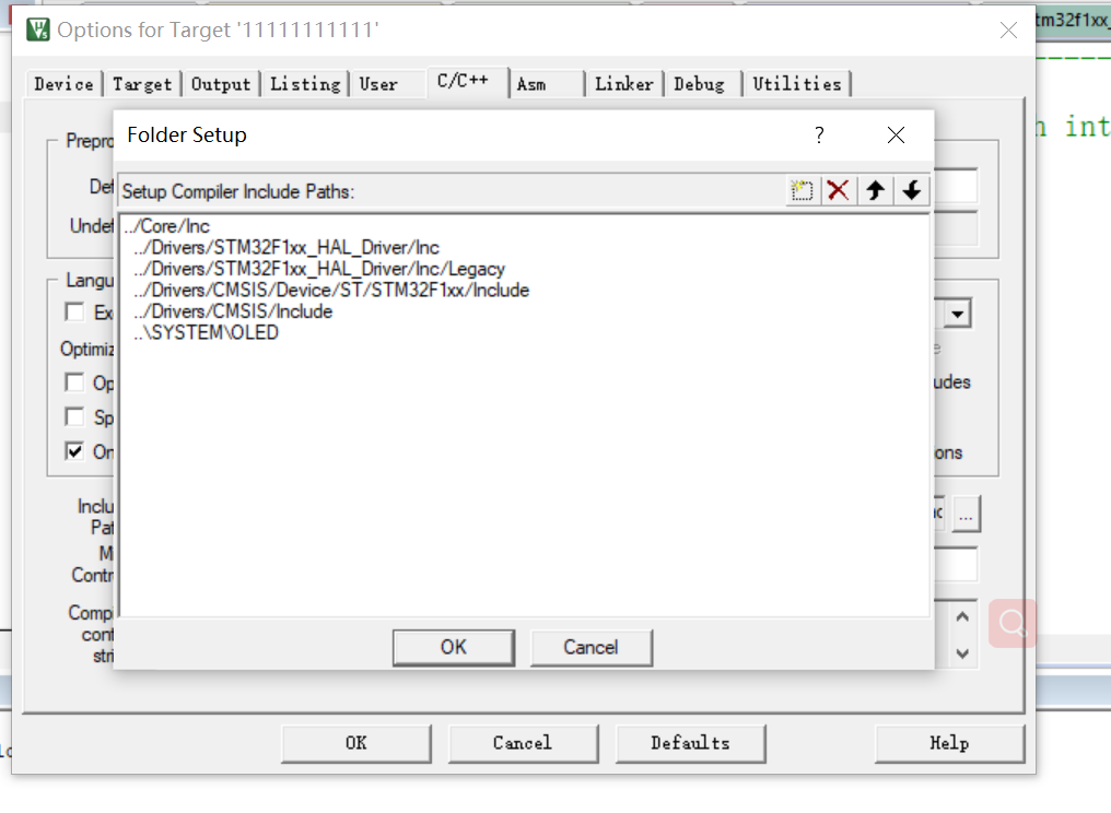
Add path
Then modify some library code (library function) inside
#define OLED_SCLK_Clr() GPIO_ResetBits(GPIOA,GPIO_Pin_5)//CLK
#define OLED_SCLK_Set() GPIO_SetBits(GPIOA,GPIO_Pin_5)

#define OLED_SDIN_Clr() GPIO_ResetBits(GPIOA,GPIO_Pin_7)//DIN
#define OLED_SDIN_Set() GPIO_SetBits(GPIOA,GPIO_Pin_7)

#define OLED_RST_Clr() GPIO_ResetBits(GPIOB,GPIO_Pin_0)//RES
#define OLED_RST_Set() GPIO_SetBits(GPIOB,GPIO_Pin_0)

#define OLED_DC_Clr() GPIO_ResetBits(GPIOB,GPIO_Pin_1)//DC
#define OLED_DC_Set() GPIO_SetBits(GPIOB,GPIO_Pin_1)

#define OLED_CS_Clr()  GPIO_ResetBits(GPIOA,GPIO_Pin_4)//CS
#define OLED_CS_Set()  GPIO_SetBits(GPIOA,GPIO_Pin_4)

#define OLED_CMD  0 	// Write command
#define OLED_DATA 1 	// Write data
Modify this paragraph as
//-----------------OLED delay macro definition----------------
#define delay_ms(x)   HAL_Delay(x)
//-----------------OLED port macro definition----------------

//HAL_GPIO_WritePin(GPIO_TypeDef *GPIOx, uint16_t GPIO_Pin, GPIO_PinState PinState)

#define OLED_SCLK_Clr() HAL_GPIO_WritePin(GPIOA,OLED_SCL_Pin,GPIO_PIN_RESET)//CLK
#define OLED_SCLK_Set() HAL_GPIO_WritePin(GPIOA,OLED_SCL_Pin,GPIO_PIN_SET)

#define OLED_SDIN_Clr() HAL_GPIO_WritePin(GPIOA,OLED_SDA_Pin,GPIO_PIN_RESET)//DIN
#define OLED_SDIN_Set() HAL_GPIO_WritePin(GPIOA,OLED_SDA_Pin,GPIO_PIN_SET)

#define OLED_RST_Clr() HAL_GPIO_WritePin(GPIOB,OLED_RES_Pin,GPIO_PIN_RESET)//RES
#define OLED_RST_Set() HAL_GPIO_WritePin(GPIOB,OLED_RES_Pin,GPIO_PIN_SET)

#define OLED_DC_Clr() HAL_GPIO_WritePin(GPIOB,OLED_DC_Pin,GPIO_PIN_RESET)//DC
#define OLED_DC_Set() HAL_GPIO_WritePin(GPIOB,OLED_DC_Pin,GPIO_PIN_SET)

#define OLED_CS_Clr()  HAL_GPIO_WritePin(GPIOA,GPIO_PIN_RESET,GPIO_PIN_RESET)//CS
#define OLED_CS_Set()  HAL_GPIO_WritePin(GPIOA,GPIO_PIN_RESET,GPIO_PIN_SET)

#define OLED_CMD  0 	// Write command
#define OLED_DATA 1 	// Write data
Initialize oled into function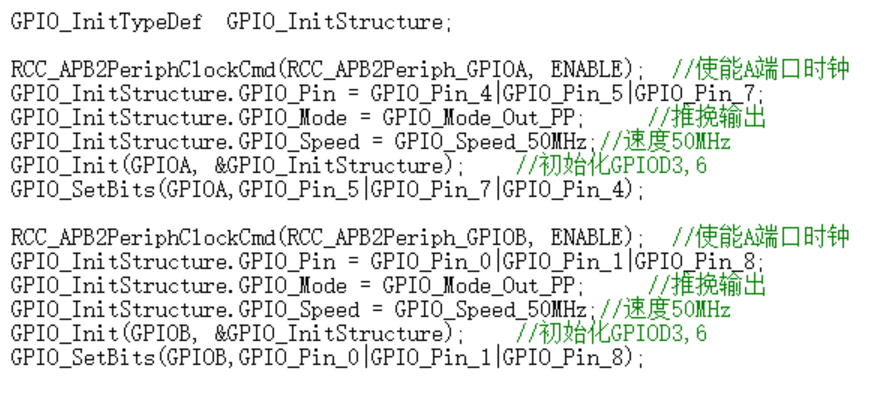 The GPIO function structure of is initialized, and these pins are initialized in MX.
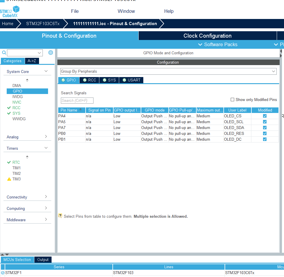
Since the GPIO initialization function is transferred to the main function, you must pay attention to OLED_ The init function should be placed after the GPIO function.
Finally, call the function in oled.c in the main function,
void oled_display()
	{
		OLED_Clear();
			OLED_ShowString(16,1,"20");
			OLED_ShowNum(32,1,GetData.Year,2,16);
			OLED_ShowCHinese(48,1,0);   //year

			OLED_ShowNum(64,1,GetData.Month,2,16);
			if(GetData.Month<10)
			{
				OLED_ShowNum(64,1,0,1,16);
			}
			OLED_ShowCHinese(80,1,1);  //month

			OLED_ShowNum(96,1,GetData.Date,2,16);
			OLED_ShowCHinese(112,1,2);  //day

			OLED_ShowNum(16,5,GetTime.Hours,2,16);
			if(GetTime.Hours<10)
			{
				OLED_ShowNum(16,5,0,1,16);
			}
			OLED_ShowCHinese(32,5,3);  //Time

			OLED_ShowNum(48,5,GetTime.Minutes,2,16);
			if(GetTime.Minutes<10)
			{
				OLED_ShowNum(48,5,0,1,16);
			}
			OLED_ShowCHinese(64,5,4);  //branch

			OLED_ShowNum(80,5,GetTime.Seconds,2,16);
			if(GetTime.Seconds<10)
			{
				OLED_ShowNum(80,5,0,1,16);
			}
			OLED_ShowCHinese(96,5,5);  //second
		}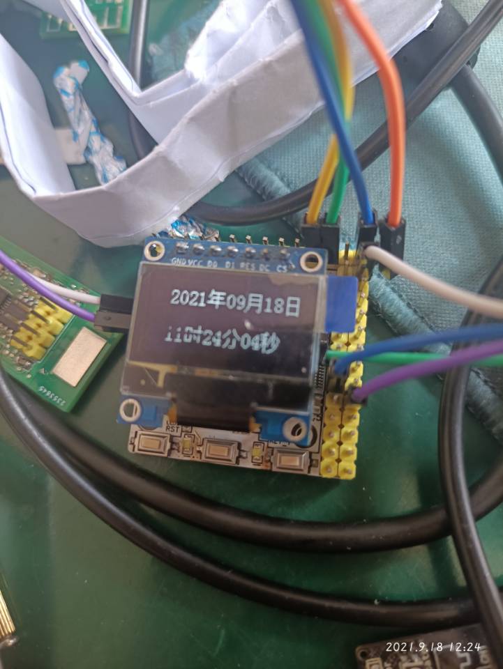
The final result.