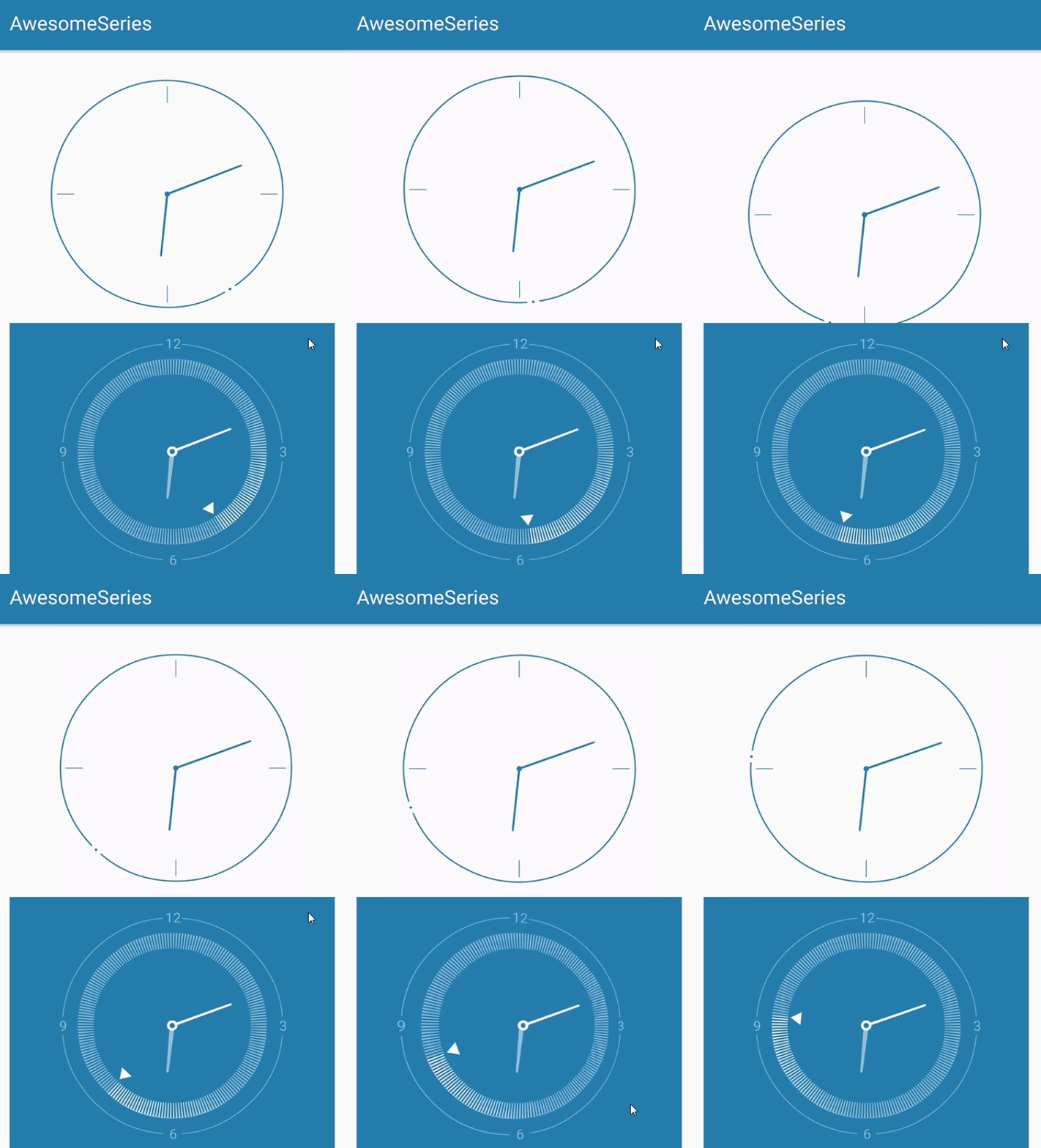
If you don't say much, first put on the effect map.

When you think the first half screen is a ghost, it's actually a direction sensor. Place the phone on the desktop, lift the left edge of the phone, tilt the clock to the right, and then tilt the edges. As for the second half of the screen, rice noodles should know that it is the clock of the MIUI system.
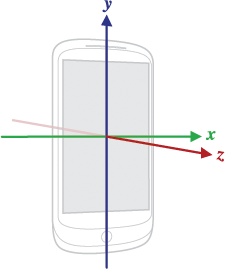
In Android platforms, sensor frameworks usually use a standard three-dimensional coordinate system to represent a value.
It's not too much to make an official picture at this time.

Direction sensor learning, concise, with example code
1. Since onSizeChanged method has completed initialization of global variables and obtained the width and height of the control before onDraw and after construction method, onMeasure, etc., some values related to width and height can be determined in this method, such as the radius of the View, padding value and so on, which is convenient for drawing. When calculating size and location:
    @Override
    protected void onSizeChanged(int w, int h, int oldw, int oldh) {
        super.onSizeChanged(w, h, oldw, oldh);
        //Width and height remove padding values, and take half of min, that is, the radius of the dial.
        mRadius = Math.min(w - getPaddingLeft() - getPaddingRight(), h - getPaddingTop() - getPaddingBottom()) / 2;
        mDefaultPadding = 0.12f * mRadius;//Default padding size based on scale
        mPaddingLeft = mDefaultPadding + w / 2 - mRadius + getPaddingLeft();
        mPaddingTop = mDefaultPadding + h / 2 - mRadius + getPaddingTop();
        mPaddingRight = mPaddingLeft;
        mPaddingBottom = mPaddingTop;
        mScaleLength = 0.12f * mRadius;//Determining the length of scale line according to proportion
    }
2. Then start drawing four scales in the direction of 3, 6, 9, 12:
    /**
     * 90 Degree a scale line
     */
    private void drawScaleLines()
    {
        mScalePadding = 0.03f * mRadius;
        mScaleLength = 0.13f * mRadius;
        mCanvas.drawLine(mPaddingLeft+mCircleStrokeWidth + mScalePadding,getHeight() / 2 , mPaddingLeft + mCircleStrokeWidth + mScalePadding + mScaleLength, getHeight() / 2, mScaleLinePaint);
        mCanvas.drawLine(getWidth() / 2,mPaddingTop + mCircleStrokeWidth + mScalePadding ,getWidth() / 2, mPaddingTop + mCircleStrokeWidth + mScalePadding + mScaleLength, mScaleLinePaint);
        mCanvas.drawLine(getWidth() - mCircleStrokeWidth - mScalePadding -mScaleLength - mPaddingRight , getHeight() / 2 ,getWidth() - mCircleStrokeWidth - mScalePadding - mPaddingRight, getHeight() / 2, mScaleLinePaint);
        mCanvas.drawLine(getWidth() / 2,getHeight()- mCircleStrokeWidth - mScalePadding -mScaleLength -mPaddingBottom ,getWidth() / 2, getHeight() - mCircleStrokeWidth - mScalePadding - mPaddingBottom, mScaleLinePaint);
    }
3. Rotating the canvas according to the changing secondhand angle, we need to calculate the angle of the notch arc mSecondHandPath.arcTo(mCircleRectF,-87,354)
    private void drawSecondHand() {
        mCanvas.save();
        mCanvas.rotate(mSecondDegree, getWidth() / 2, getHeight() / 2);
        mSecondHandPath.reset();
        mCircleRectF.set(mPaddingLeft,mPaddingTop,getWidth()-mPaddingRight,getHeight()-mPaddingBottom);
        mSecondHandPath.arcTo(mCircleRectF,-87,354);
        mSecondHandPaint.setStyle(Paint.Style.STROKE);
        mSecondHandPaint.setStrokeWidth(mCircleStrokeWidth);
        mCanvas.drawPath(mSecondHandPath, mSecondHandPaint);
        mCircleRectF.set(getWidth() / 2 - mCircleStrokeWidth,mPaddingTop-mCircleStrokeWidth,getWidth() / 2  + mCircleStrokeWidth ,mPaddingTop + mCircleStrokeWidth);
        mSecondHandPaint.setStyle(Paint.Style.FILL);
        mCanvas.drawArc(mCircleRectF, 0, 360, false, mSecondHandPaint);
        mCanvas.restore();
    }
4. The clockwise needle is similar to the minute needle. The needle is circular. Then the second-order Bessel curve is used. The paths are moveTo (A), lineTo (B), quadTo (C, D), lineTo (E), close.
    private void drawHourHand() {
        mCanvas.save();
        mCanvas.rotate(mHourDegree, getWidth() / 2, getHeight() / 2);
        mHourHandPath.reset();
        float offset = mPaddingTop ;
        mHourHandPath.moveTo(getWidth() / 2 - 0.008f * mRadius, getHeight() / 2 - 0.01f * mRadius);
        mHourHandPath.lineTo(getWidth() / 2 - 0.007f * mRadius, offset + 0.4f * mRadius);
        mHourHandPath.quadTo(getWidth() / 2, offset + 0.38f * mRadius, getWidth() / 2 + 0.007f * mRadius, offset + 0.4f * mRadius);
        mHourHandPath.lineTo(getWidth() / 2 + 0.008f * mRadius, getHeight() / 2 - 0.02f * mRadius);
        mHourHandPath.close();
        mHourHandPaint.setStyle(Paint.Style.FILL);
        mCanvas.drawPath(mHourHandPath, mHourHandPaint);
        mCircleRectF.set(getWidth() / 2 - 0.02f * mRadius, getHeight() / 2 - 0.02f * mRadius, getWidth() / 2 + 0.02f * mRadius, getHeight() / 2 + 0.02f * mRadius);
        mCanvas.drawArc(mCircleRectF, 0, 360, false, mHourHandPaint);
        mCanvas.restore();
    }
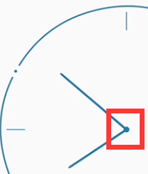
A graph gives you a thorough understanding of second-order Bessel curves.
5. Finally, because the path is close, we simply draw two circles on it.
        mCircleRectF.set(getWidth() / 2 - 0.02f * mRadius, getHeight() / 2 - 0.02f * mRadius,
        getWidth() / 2 + 0.02f * mRadius, getHeight() / 2 + 0.02f * mRadius);
        mCanvas.drawArc(mCircleRectF, 0, 360, false, mHourHandPaint);

6. Hot? Next is how to realize the direction sensor.
Register the sensor in the constructor:
        sManager = (SensorManager) context.getSystemService(SENSOR_SERVICE);
        mSensorOrientation = sManager.getDefaultSensor(Sensor.TYPE_ORIENTATION);
        sManager.registerListener(this, mSensorOrientation SensorManager.SENSOR_DELAY_UI);
Implementation of Sensor EventListener Interface
    @Override
    public void onSensorChanged(SensorEvent sensorEvent) {
        int tbValue = (Math.round(sensorEvent.values[1]));
        int lrValue = (Math.round(sensorEvent.values[2]));
        offsetTopAndBottom(tempTBValue - tbValue);
        offsetLeftAndRight(tempLRValue - lrValue);
        tempTBValue = tbValue;
        tempLRValue = lrValue;
    }
OVER!
Lu Xun said: Don't bb, show me the code!

Source address: https://github.com/ftc300/AwesomeClock
At the same time, I will regularly update my blog to my website in the future. Welcome to visit: https://ftc300.github.io/