Keyboard & Mouse interrupt implementation
This section mainly realizes keyboard interruption and mouse interruption, keyboard interruption realizes keyboard data display to the screen; mouse interruption realizes the movement of mouse position.
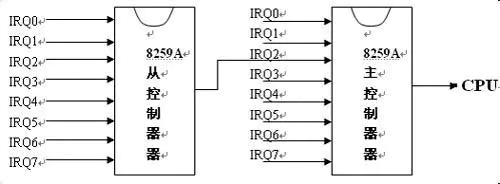
Keyboard interrupt is triggered by IRQ1 of 8259A and mouse interrupt is triggered by IRQ4 of 8259A
CPU uses interrupt vector number to address the interrupt code to be executed
Interrupt vector number = start vector number + interrupt request number
The start vector number is initialized by the interrupt control word ICW2. The interrupt request number is 8259A pin number
Turn on main IRQ1 and interrupt response pin from IRQ4
    ;OCW(operation control word)
	;When OCW[i] = 1 Time,Shielding corresponding IRQ(i)Signal of pipeline
	;IRQ1 Corresponding to the interruption caused by keyboard
    mov al, 11111001b
    out 021h, al
    call io_delay

    ;CPU Ignore all from 8259 A Chip signal
	;The mouse is powered by A Of IRQ4 Tube alignment CPU Sending signal
    mov al, 11101111b
    out 0A1h, al
    call io_delay
The initialization interrupt control word ICW2 is as follows:
;To the Lord 8259 A Send out ICW2
	;20h Corresponding binary 00100000
	;ICW2[0,1,2] = 0
	;8259A According to the set start vector number (the start vector number passes the interrupt control word ICW2 Initialized) plus interrupt request number to calculate interrupt vector number
	;When Lord 8259 A Corresponding IRQ0 Tube alignment CPU When sending a signal, CPU According to 0 x20 This value is used to find the code to be executed,
	;,CPU According to 0 x21 This value finds the code to execute, and so on.
    mov al, 020h
    out 021h, al
    call io_delay

	;From 8259 A Send out ICW2
	;28h Corresponding binary 00100100
	;8259A According to the set start vector number (the start vector number passes the interrupt control word ICW2 Initialized) plus interrupt request number to calculate interrupt vector number
	;When from 8259 A Corresponding IRQ0 Tube alignment CPU When sending a signal, CPU According to 0 x28 This value is used to find the code to be executed,
	;IRQ1 Tube alignment CPU When sending a signal, CPU According to 0 x29 This value finds the code to execute, and so on.
    mov al, 028h
    out 0A1h, al
    call io_delay
The starting vector number of the master controller is 0x20 and the starting vector number of the slave controller is 0x28. Therefore
Keyboard interrupt vector number is 0x20+0x01=0x21
The interrupt vector number of mouse is 0x28+0x04=0x2c
Therefore, the interrupt descriptor is initialized as follows:
;Interrupt descriptor table
LABLE_IDT:
    %rep 0x21
        Gate SelectorCode32, SpuriousHandler, 0, DA_386IGate
    %endrep

	;Keyboard interrupt vector(8259A Keyboard interrupt vector 0 x20,IRQ1 Is a keyboard interrupt request,0x20 + IRQ[n] = 0x21
	.0x21:
		Gate SelectorCode32, KeyboardHandler, 0, DA_386IGate

	%rep 10
		Gate SelectorCode32, SpuriousHandler, 0, DA_386IGate
	%endrep

	;Slave interrupt controller 8259 A Interrupt vector 0 x28,IRQ4 It's a mouse interrupt request,0x28 + IRQ[n] = 0x2c
	.0x2c:
		Gate SelectorCode32, MouseHandler, 0, DA_386IGate
Corresponding keyboard and mouse interrupt handling functions:
;Keyboard interrupt program
LabelKeyboardHandler:
	KeyboardHandler EQU LabelKeyboardHandler - $$
	; Pay attention to interrupt the switching process
	push es
	push ds
	pushad
	mov eax, esp
	push eax

	call int_keyboard

	pop eax
	mov esp, eax
	popad
	pop ds
	pop es
	iretd

;Mouse interrupt program
LabelMouseHandler:
	MouseHandler EQU LabelMouseHandler - $$
	; Pay attention to interrupt the switching process
	push es
	push ds
	pushad
	mov eax, esp
	push eax

	call int_mouse

	pop eax
	mov esp, eax
	popad
	pop ds
	pop es
	iretd
The process of interrupt processing function
Stack the current register value
Execute interrupt response function
Recover the register value in the stack and continue to execute the pre interrupt instruction
Keyboard interrupt response function
void int_keyboard(char *index){

        //0x20 is 8259A control port

        //0x21 corresponds to the interrupt vector of the keyboard. When the keyboard interrupt is executed by the CPU, the next time the keyboard sends a signal to the CPU,

        //The CPU will not receive the signal. In order for the CPU to receive the signal again, it must send the interrupt vector number of the keyboard interrupt to the port of the main PIC again

        io_out8(0x20, 0x21);

        unsigned char data = io_in8(PORT_KEYDATA);

        fifo8_put(&keybufInfo, data);

}
The data generated by keyboard interrupt is stored in the queue, and the main function continuously detects whether there is data in the queue. If there is data, the corresponding data will be displayed in the screen
    for(;;){
		if (keybufInfo.len > 0) {
			io_cli();
			static char keyval[4] = {'0','x'};
			for(int i=0; i<keybufInfo.len; i++){
				char data = fifo8_get(&keybufInfo);
				static int x = 0;
				char2HexStr(data, keyval);
				showString(keyval, x%SCREEN_WIDTH, x/SCREEN_WIDTH*20, COL8_FFFFFF);
				x += 32;
			}
			io_seti();
		} else if (mousebufInfo.len > 0) {
			io_cli();
			for(int t=0;t<mousebufInfo.len;t++){
				mouseCursorMoved(&mouseDes, COL8_008484);
			}
			io_seti();
		} else {
			io_hlt();
		}
    }
Mouse circuit initialization
The kernel is loaded and the interrupt descriptor table is initialized. In order to respond to the mouse interrupt, the initialization of the mouse circuit needs to be implemented first
//Initialize the keyboard control circuit, the mouse control circuit is connected to the keyboard control circuit, through the keyboard circuit to achieve initialization
void init_mouse(){

	waitKBCReady();

	//0x60 enter the keyboard circuit into the data acceptance state
	io_out8(PORT_KEYCMD, KEYCMD_WRITE_MODE);
	waitKBCReady();

	//Data 0x47 requires the keyboard circuit to start the mouse mode, so that the data information generated by the mouse hardware can be read through the keyboard circuit port 0x60
	io_out8(PORT_KEYDATA, KBC_MODE);
	waitKBCReady();

	io_out8(PORT_KEYCMD, KEYCMD_SENDTO_MOUSE);
	waitKBCReady();

	//0xf4 data activate mouse circuit, which will send interrupt signal to CPU after activation
	io_out8(PORT_KEYDATA, MOUSECMD_ENABLE);
}
The mouse circuit can only accept commands from the kernel when the second bit of port 0x64 data is 0.
//A port corresponding to the mouse circuit is 0x64. The state of the mouse circuit is detected by reading the data of this port,
//The kernel will read a byte of data from this port. If the second bit of the byte is 0, it means that the mouse circuit can
//Accept commands from the kernel, so before sending data to the mouse circuit, the kernel needs to repeatedly read data from port 0x64,
//The second bit of the read data is detected, and the control information is not sent until the bit is 0
void waitKBCReady(){
	for(;;){
		if((io_in8(PORT_KEYSTA)&0x02)==0){
			break;
		}
	}
}
Mouse interrupt response function
In the mouse interrupt response function, the data generated by mouse interrupt is stored in the queue
void int_mouse(char *index){

        //After interrupt processing, if you want to receive the interrupt signal again, you must send a byte of data to the interrupt controller

        io_out8(0x20, 0x20);

        io_out8(0xa0, 0x20);

        //Read mouse data

        unsigned char data = io_in8(PORT_MOUSEDATA);

        fifo8_put(&mousebufInfo, data);

}
The main loop continuously detects the mouse queue and processes each data in turn
        for(;;){
		if (keybufInfo.len > 0) {
			io_cli();
			static char keyval[4] = {'0','x'};
			for(int i=0; i<keybufInfo.len; i++){
				char data = fifo8_get(&keybufInfo);
				static int x = 0;
				char2HexStr(data, keyval);
				showString(keyval, x%SCREEN_WIDTH, x/SCREEN_WIDTH*20, COL8_FFFFFF);
				x += 32;
			}
			io_seti();
		} else if (mousebufInfo.len > 0) {
			io_cli();
			for(int t=0;t<mousebufInfo.len;t++){
				mouseCursorMoved(&mouseDes, COL8_008484);
			}
			io_seti();
		} else {
			io_hlt();
		}
    }
Read the data in the queue, every three for a group of analysis, every three data structure MouseDes to represent the current mouse movement information, then erase the old mouse information, calculate the new mouse coordinates, draw the new mouse.
void mouseCursorMoved(MouseDes *mdec, char bc){
	unsigned char data = fifo8_get(&mousebufInfo);
	if(mouse_decode(mdec, data) != 0){
		//Mouse position before erasing
		fillRect(mdec->x, mdec->y, 16, 16, bc);
		//Calculate new mouse coordinates
		mdec->x += mdec->offX;
		mdec->y += mdec->offY;
		if(mdec->x < 0){
			mdec->x = 0;
		}
		if(mdec->x > SCREEN_WIDTH-16/2){
			mdec->x = SCREEN_WIDTH-16/2;
		}
		if(mdec->y < 0){
			mdec->y = 0;
		}
		if(mdec->y > SCREEN_HEIGHT-16){
			mdec->y = SCREEN_HEIGHT-16;
		}
		//Draw mouse
		init_mouse_cursor((char *)VGA_ADDR, mdec->x, mdec->y, COL8_008484);
	}
}
Mouse movement model and processing
//Mouse processing needs to process 3 bytes continuously
//Phase means processing byte phase
//Offset of the current mouse
//x. Y the current coordinate position of the mouse
typedef struct _MouseDes{
	char buf[3], phase;
	int offX, offY;
	int x, y, btn;
}MouseDes;
Every three data can give the data information of mouse interruption, mainly including the type of mouse button (left pulley right)
Move the mouse up and down to move the data left and right. First byte 0xab, The value of a must be in the range of 0-3. Since a corresponds to the upper four bits of the eight bits, it means that the seventh and eighth bits of the byte must be 0, and b corresponds to the lower four bits of the eight bits. Its value must be between 8-F, which means that the fourth bit of the byte data must be 1. To convert the first byte into binary, it must meet the following requirements: Face format (X, * for 0 or 1):
0 0 X X 1 * \ * * three * are used to represent the mouse button. When the left key, wheel and right key of the mouse are pressed, the corresponding bit will be set to 1. The second byte is used to represent the left and right movement of the mouse. After corresponding processing of the byte, the coordinate transformation of mouse translation can be obtained. The data of the third byte represents the up and down movement of the mouse. After the corresponding processing of the byte, the coordinate number change when the mouse moves vertically can be obtained.
The specific process is as follows:
int mouse_decode(MouseDes *mdec, unsigned char dat){
	int flag = -1;
	if(mdec->phase == 0){
		if(dat == 0xfa){
			mdec->phase = 1;
		}
		flag = 0;
	}
	else if(mdec->phase == 1){
		if((dat&0xc8) == 0x08){
			mdec->buf[0] = dat;
			mdec->phase = 2;
		}
		flag = 0;
	}
	else if(mdec->phase == 2){
		mdec->buf[1] = dat;
		mdec->phase = 3;
		flag = 0;
	}
	else if(mdec->phase == 3){
		mdec->buf[2] = dat;
		mdec->phase  =1;
		mdec->btn = mdec->buf[0]&0x07;
		mdec->offX = mdec->buf[1];
		mdec->offY = mdec->buf[2];
		if((mdec->buf[0]&0x10) != 0){
			mdec->offX |= 0xffffff00;
		}
		if((mdec->buf[0]&0x20) != 0){
			mdec->offY |= 0xffffff00;
		}
		mdec->offY = -mdec->offY;
		flag = 1;
	}
	return flag;
}
Code location: https://github.com/ChenWenKaiVN/bb_os_core
Reference link:

