1, AHT20 realizes data acquisition of temperature and humidity
1. Brief description of I2C protocol layer
(1) Communication process of I2C protocol

These figures show the data packet sequence of SDA line when master and slave communicate.
Where S represents the transmission start signal (S) generated by the I2C interface of the host. At this time, it is connected to all devices on the I2C bus
The slave will receive this signal.
After the start signal is generated, all slaves begin to wait for the slave address signal broadcast by the host next
(SLAVE_ADDRESS). On the I2C bus, the address of each device is unique. When the address broadcast by the host is different from
When the address of a device is the same, the device is selected, and the unselected device will ignore the subsequent data signal.
According to the I2C protocol, the slave address can be 7 bits or 10 bits.
After the address bit is the selection bit of the transmission direction. When this bit is 0, it indicates that the subsequent data transmission direction is determined by the master
The master transfers data to the slave, that is, the master writes data to the slave. When this bit is 1, it is the opposite, that is, the host reads data from the slave.
After the slave receives the matching address, the master or slave returns an ACK or NACK signal,
Only after receiving the response signal can the host continue to send or receive data.
(2) Start and stop signals of communication
Start (S) and stop signals are two special states, as shown in figure 24-5. When SCL line is high
At ordinary times, SDA line switches from high level to low level, which indicates the beginning of communication. SDA when SCL is high
The line switches from low level to high level, indicating the stop of communication. Start and stop signals are generally generated by the host.

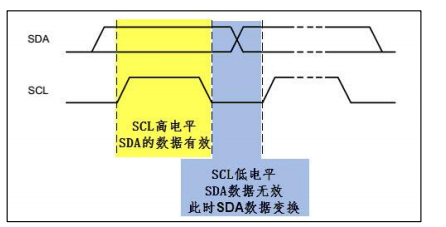
(3) Data validity
I2C uses SDA signal line to transmit data and SCL signal line to synchronize data. See figure 24-6. SDA number
The data line transmits one bit of data in each clock cycle of SCL. Data represented by SDA when SCL is high during transmission
Valid, that is, SDA at this time indicates data "1" at high level and data "0" at low level. When SCL is low
At normal level, SDA data is invalid. Generally, SDA performs level switching at this time to prepare for the next presentation of data
Ready.
Each data transmission is in bytes, and the number of bytes transmitted each time is unlimited.
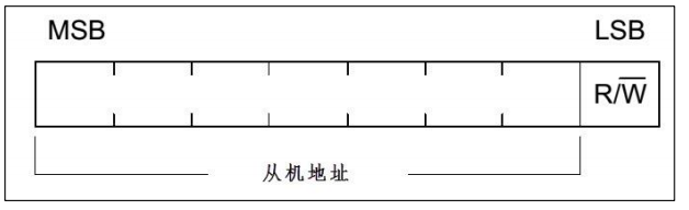
(4) Address and data direction
Each device on the I2C bus has its own independent address. When the host initiates communication, it sends the device address (SLAVE_ADDRESS) through the SDA signal line to find the slave. I2C protocol stipulates that the device address can be 7 bits or 10 bits. In practice, 7-bit address is widely used. A data bit immediately following the device address is used to indicate the data transmission direction. It is the data direction bit (R/W -), bit 8 or bit 11. When the data direction bit is "1", it indicates that the host reads data from the slave, and when this bit is "0", it indicates that the host writes data to the slave.
When reading the data direction, the host will release the control of SDA signal line, the slave will control SDA signal line, and the host will connect
When receiving signal and writing data direction, SDA is controlled by the host and receives signal from the slave.
(5) Respond
The data and address transmission of 2C is response. Responses include "ack" and "NACK"
Signal. As the data receiving end, when the device (regardless of the master and slave) receives a byte data or address transmitted by I2C,
If you want the other party to continue to send data, you need to send an "ack" signal to the other party, and the sender will continue to send the next message
One data; If the receiving end wants to end the data transmission, it sends a "non response (NACK)" signal to the other party, and the sender connects
After receiving this signal, a stop signal will be generated to end the signal transmission.

During transmission, the host generates a clock. At the 9th clock, the data transmitting end will release the control right of SDA and the data will be connected
The receiving terminal controls SDA. If SDA is at high level, it indicates non response signal (NACK), and low level indicates response signal (ACK).
2. What are software I2C and hardware I2C
If we directly control the two GPIO pins of STM32 to be used as SCL and SDA respectively, according to the above signal
Timing requirements: directly control the output of the pin like controlling the LED lamp (read the SDA level when receiving data)
I2C communication can be realized. Similarly, if we control the pin according to the requirements of USART, USART can also be turned on
News. So as long as you abide by the protocol, it is standard communication. No matter how you implement it, whether the controller produced by ST is still in use
It is a memory produced by ATMEL and can interact according to communication standards.
-
Software I2C
When directly controlling the GPIO pin level to generate communication sequence, the CPU needs to control the pin state at each time in the "software simulation protocol" mode -
Hardware I2C
The I2C on-chip peripheral of STM32 is specially responsible for implementing the I2C communication protocol. As long as the peripheral is configured, it will automatically generate communication signals according to the protocol requirements, send and receive data and cache it. As long as the CPU detects the status of the peripheral and accesses the data register, it can complete data sending and receiving.
3. AHT20 realizes the collection of temperature and humidity data
(1) About code
Download link of programming code: Complete code
Please refer to the blog for specific code addition steps https://blog.csdn.net/hhhhhh277523/article/details/111397514
(2) Main code -
AHT20 chip
void  read_AHT20_once(void)
{
	delay_ms(10);

	reset_AHT20();//Reset AHT20 chip
	delay_ms(10);

	init_AHT20();//Initialize AHT20 chip
	delay_ms(10);

	startMeasure_AHT20();//Start testing AHT20 chip
	delay_ms(80);

	read_AHT20();//Read the data collected by AHT20
	delay_ms(5);
}
- AHT20 chip reads data
void read_AHT20(void)
{
	uint8_t   i;

	for(i=0; i<6; i++)
	{
		readByte[i]=0;
	}
	I2C_Start();//I2C start

	I2C_WriteByte(0x71);//I2C write data
	ack_status = Receive_ACK();//Received response information
	readByte[0]= I2C_ReadByte();//I2C read data
	Send_ACK();//Send response information

	readByte[1]= I2C_ReadByte();
	Send_ACK();

	readByte[2]= I2C_ReadByte();
	Send_ACK();

	readByte[3]= I2C_ReadByte();
	Send_ACK();

	readByte[4]= I2C_ReadByte();
	Send_ACK();

	readByte[5]= I2C_ReadByte();
	SendNot_Ack();
	//Send_ACK();

	I2C_Stop();//I2C stop function
	//Judge whether the first byte read is 0x08, which is specified in the chip reading process. If there is no problem in the reading process, process the read data accordingly
	if( (readByte[0] & 0x68) == 0x08 )
	{
		H1 = readByte[1];
		H1 = (H1<<8) | readByte[2];
		H1 = (H1<<8) | readByte[3];
		H1 = H1>>4;

		H1 = (H1*1000)/1024/1024;

		T1 = readByte[3];
		T1 = T1 & 0x0000000F;
		T1 = (T1<<8) | readByte[4];
		T1 = (T1<<8) | readByte[5];

		T1 = (T1*2000)/1024/1024 - 500;

		AHT20_OutData[0] = (H1>>8) & 0x000000FF;
		AHT20_OutData[1] = H1 & 0x000000FF;

		AHT20_OutData[2] = (T1>>8) & 0x000000FF;
		AHT20_OutData[3] = T1 & 0x000000FF;
	}
	else
	{
		AHT20_OutData[0] = 0xFF;
		AHT20_OutData[1] = 0xFF;

		AHT20_OutData[2] = 0xFF;
		AHT20_OutData[3] = 0xFF;
		printf("Read failed!!!");

	}
	printf("\r\n");
	//According to the calculation formula of temperature and humidity in AHT20 chip, the final result is obtained and displayed through serial port
	printf("temperature:%d%d.%d",T1/100,(T1/10)%10,T1%10);
	printf("humidity:%d%d.%d",H1/100,(H1/10)%10,H1%10);
	printf("\r\n");
}
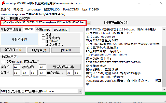
(3) Compile and generate hex files and burn them

(4) Open the serial port debugging assistant to view the temperature and humidity data acquisition results
-
Temperature and humidity when opening the serial port debugging assistant
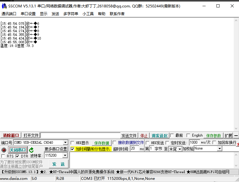
-
Temperature and humidity displayed after breathing on the chip

It can be seen that the temperature and humidity increase
2, OLED display based on SPI bus
1. The SPI or IIC interface of STM32 displays the temperature and humidity of AHT20
(1) Download and display project code
OLED display code link

- Temperature and humidity display code
void read_AHT20(void)
{
uint8_t i;
for(i=0; i<6; i++)
{
readByte[i]=0;
}
//-------------
I2C_Start();
I2C_WriteByte(0x71);
ack_status = Receive_ACK();
readByte[0]= I2C_ReadByte();
Send_ACK();
readByte[1]= I2C_ReadByte();
Send_ACK();
readByte[2]= I2C_ReadByte();
Send_ACK();
readByte[3]= I2C_ReadByte();
Send_ACK();
readByte[4]= I2C_ReadByte();
Send_ACK();
readByte[5]= I2C_ReadByte();
SendNot_Ack();
//Send_ACK();
I2C_Stop();
//--------------
if( (readByte[0] & 0x68) == 0x08 )
{
H1 = readByte[1];
H1 = (H1<<8) | readByte[2];
H1 = (H1<<8) | readByte[3];
H1 = H1>>4;
H1 = (H1*1000)/1024/1024;
T1 = readByte[3];
T1 = T1 & 0x0000000F;
T1 = (T1<<8) | readByte[4];
T1 = (T1<<8) | readByte[5];
T1 = (T1*2000)/1024/1024 - 500;
AHT20_OutData[0] = (H1>>8) & 0x000000FF;
AHT20_OutData[1] = H1 & 0x000000FF;
AHT20_OutData[2] = (T1>>8) & 0x000000FF;
AHT20_OutData[3] = T1 & 0x000000FF;
}
else
{
AHT20_OutData[0] = 0xFF;
AHT20_OutData[1] = 0xFF;
AHT20_OutData[2] = 0xFF;
AHT20_OutData[3] = 0xFF;
printf("lyy");
}
/*Display the collected temperature and humidity through the serial port
printf("\r\n");
printf("Temperature:% d%d.%d",T1/100,(T1/10)%10,T1%10);
printf("Humidity:% d%d.%d",H1/100,(H1/10)%10,H1%10);
printf("\r\n");*/
t=T1/10;
t1=T1%10;
a=(float)(t+t1*0.1);
h=H1/10;
h1=H1%10;
b=(float)(h+h1*0.1);
sprintf(strTemp,"%.1f",a); //Call the Sprintf function to format the temperature data of DHT11 into the string array variable strTemp
sprintf(strHumi,"%.1f",b); //Call the Sprintf function to format the humidity data of DHT11 into the string array variable strHumi
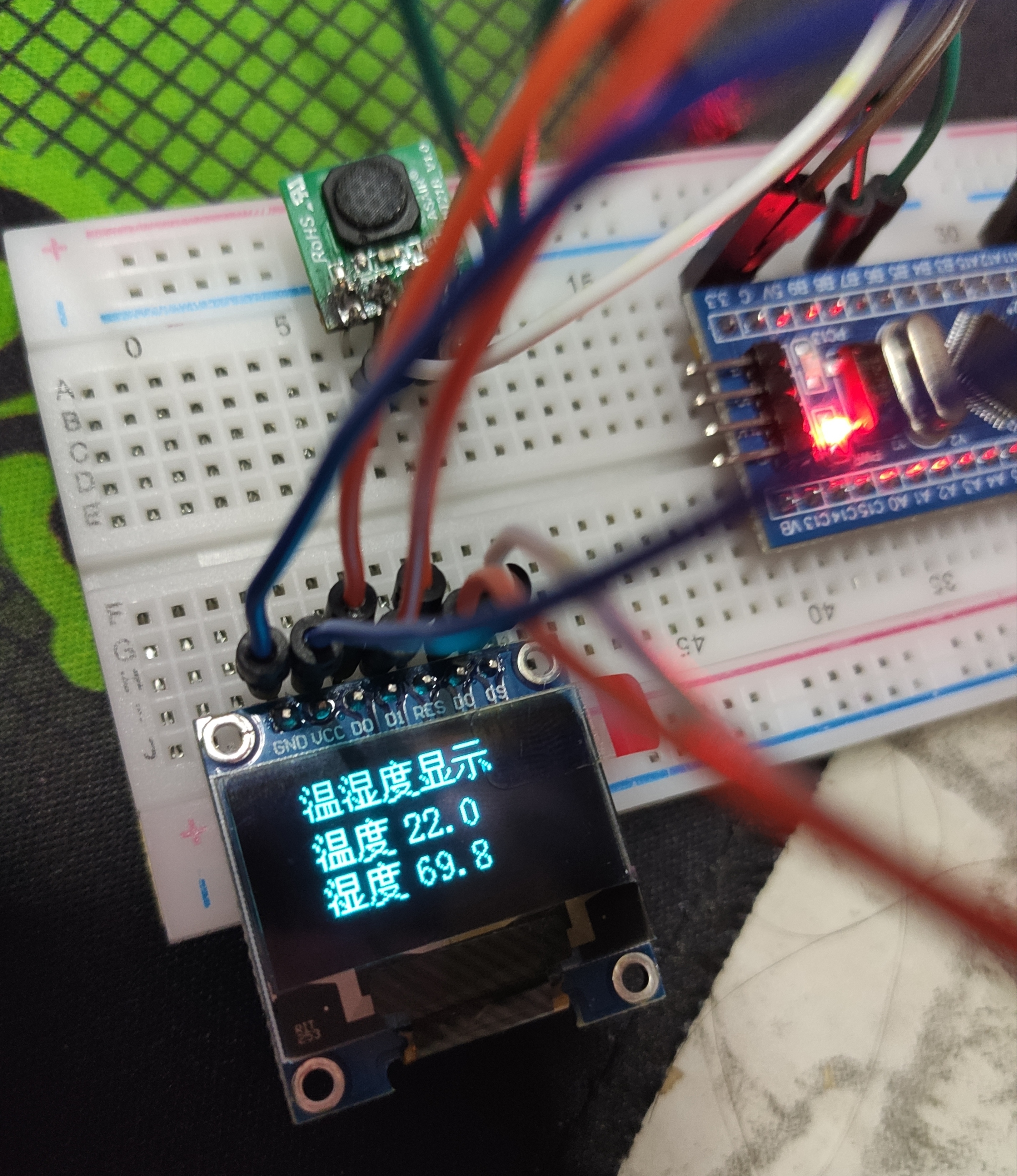
GUI_ShowCHinese(16,00,16,"Temperature and humidity display",1);
GUI_ShowCHinese(16,20,16,"temperature",1);
GUI_ShowString(53,20,strTemp,16,1);
GUI_ShowCHinese(16,38,16,"humidity",1);
GUI_ShowString(53,38,strHumi,16,1);
delay_ms(1500);
delay_ms(1500);
}
- main function
#include "delay.h"
#include "usart.h"
#include "bsp_i2c.h"
#include "sys.h"

#include "oled.h"
#include "gui.h"
#include "test.h"

int main(void)
{
	delay_init();	    	       //Delay function initialization
	uart_init(115200);
	IIC_Init();

	NVIC_Configuration(); 	   //Set NVIC interrupt packet 2: 2-bit preemption priority and 2-bit response priority
	OLED_Init();			         //Initialize OLED
	OLED_Clear(0);
	while(1)
	{
		//printf("temperature and humidity display");
		read_AHT20_once();
		OLED_Clear(0);
		delay_ms(1500);
  }
}
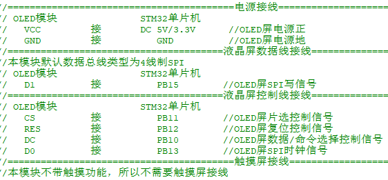
(2) Hardware wiring
-
OLED
-
AHT20

-
USB serial port

(3) Open the previous display code, compile and generate hex file, and burn
(4) The results show that
2. The SPI or IIC interface of STM32 displays the student number and name
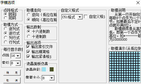
(1) Open the Chinese character mold taking software to generate the font
Network disk download link (extraction code jdzg)
- Related settings
- Input text to generate font
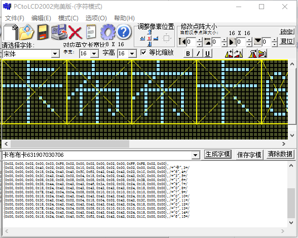
(2) Add a copy of the font encoding to the 16 * 16 portion of the code oledfont.h
- Display code
void TEST_Chinese(void)
{
	GUI_ShowString(16,0,"631907030706",8,1);//Student number
	GUI_ShowCHinese(16,20,16,"Kabuka",1);//full name
	delay_ms(1000);
	OLED_Clear(0);
}
- main function
int main(void)
{
	delay_init();	    	       //Delay function initialization
	uart_init(115200);
	IIC_Init();

	NVIC_Configuration(); 	   //Set NVIC interrupt packet 2: 2-bit preemption priority and 2-bit response priority
	OLED_Init();			         //Initialize OLED
	OLED_Clear(0);
	while(1)
	{
		TEST_Chinese();
		OLED_Clear(0);
		delay_ms(1500);
  }
}
(3) Compile and generate hex files, burn and observe the results
Kabuka
3. Slide up and down or left and right to display long characters
(1) Open the font software to generate the font

(2) Add font encoding to code
- Display code
void TEST_MainPage(void)
{
	GUI_ShowCHinese(10,20,16,"Kaka, welcome!",1);
	delay_ms(1500);
	delay_ms(1500);
}
- main function
int main(void)
{
	delay_init();	    	       //Delay function initialization
	uart_init(115200);
	IIC_Init();

	NVIC_Configuration(); 	   //Set NVIC interrupt packet 2: 2-bit preemption priority and 2-bit response priority
	OLED_Init();			         //Initialize OLED
	OLED_Clear(0);
	while(1)
	{
 		OLED_WR_Byte(0x2e,OLED_CMD);//Off scroll
   		OLED_WR_Byte(0x2a,OLED_CMD);//29 right, 2a left (scroll vertically and horizontally)
    	OLED_WR_Byte(0x00,OLED_CMD);//A: Empty byte
    	OLED_WR_Byte(0x00,OLED_CMD);//B: Horizontal start page
    	OLED_WR_Byte(0x00,OLED_CMD);//C: Horizontal rolling speed
    	OLED_WR_Byte(0x07,OLED_CMD);//D: Horizontal end page
    	OLED_WR_Byte(0x01,OLED_CMD);//E: Displacement per vertical roll
		OLED_WR_Byte(0x2f,OLED_CMD);//On scroll
		TEST_MainPage();//Content displayed
		OLED_Clear(0);
		delay_ms(1500);
  }
}
(3) Compile and burn, observe the results
Kaka, welcome
3, Summary
Everything is difficult at the beginning. At the beginning, I still can't understand how to display characters on the OLED display screen. Later, I refer to several blogs of senior students, sisters and other bloggers to understand the process of a series of steps, analyze the realization of the code in the exploration process, and understand the coding and modulus principle of Chinese dot matrix font. In the step of completing OLED display, the problems of incomplete display of characters and non display of digital parts are gradually solved.