Configure the tracking interface and authentication of VRRP
Principle overview:
When there is a problem with the uplink interface of the Master device of VRRP, and the Master device remains Active, the network will be interrupted. Therefore, the operation status of VRRP must be associated with the uplink interface. In the network configured with VRRP redundancy, in order to further improve the reliability of the network, it is necessary to configure uplink interface monitoring on the Master device to monitor the outgoing interface connected to the external network. That is, when the interface is disconnected, the priority will be automatically reduced by a certain value (the value is manually configured), so that the reduced priority is less than the priority of the Backup device, so that the Backup device will seize the Master role to take over the work;
VRRP supports message authentication. By default, the device does not process the VRRP messages to be sent and received, and considers that the received VRRP messages are real and legal. In order to make VRRP run more safely and stably, VRRP authentication can be configured. VRRP supports simple authentication and MD5 authentication. Users can choose the authentication method according to their security needs;
Purpose of the experiment:
Understand the application scenarios of VRRP monitoring interface
Master the configuration method of VRRP monitoring interface
Master the configuration method of VRRP certification
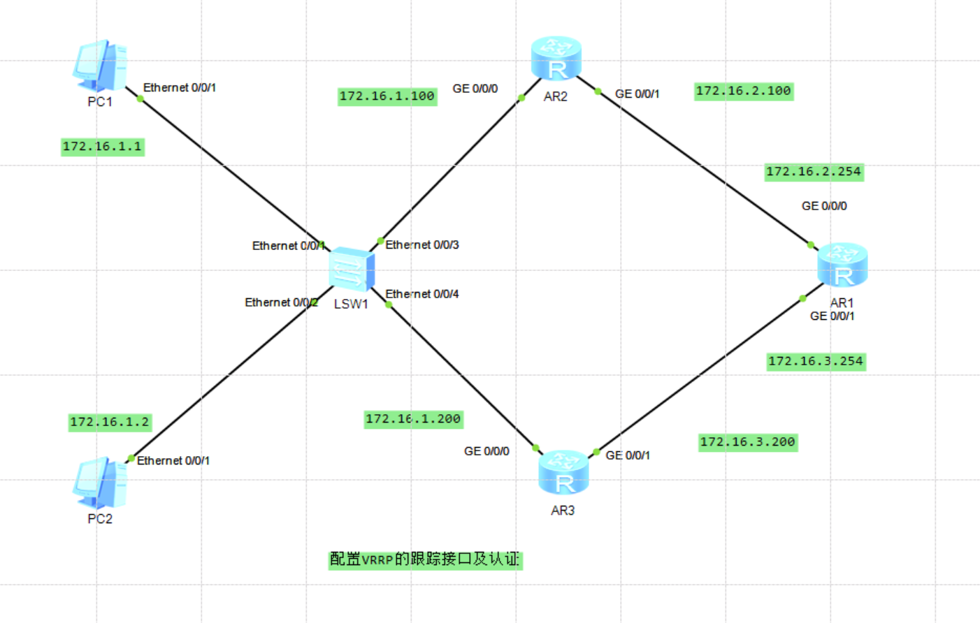
Basic configuration:
AR2:

#

interface GigabitEthernet0/0/0

 ip address 172.16.1.100 255.255.255.0

#

interface GigabitEthernet0/0/1

 ip address 172.16.2.100 255.255.255.0

#

interface NULL0

#

ospf 1

 area 0.0.0.0

  network 172.16.1.0 0.0.0.255

  network 172.16.2.0 0.0.0.255

AR1:

#

interface GigabitEthernet0/0/0

 ip address 172.16.2.254 255.255.255.0

#

interface GigabitEthernet0/0/1

 ip address 172.16.3.254 255.255.255.0

#

interface NULL0

#

ospf 1

 area 0.0.0.0

  network 172.16.2.0 0.0.0.255

  network 172.16.3.0 0.0.0.255

AR3:

#

interface GigabitEthernet0/0/0

 ip address 172.16.1.100 255.255.255.0

#

interface GigabitEthernet0/0/1

 ip address 172.16.3.200 255.255.255.0

#

interface NULL0

#

ospf 1

 area 0.0.0.0

  network 172.16.1.0 0.0.0.255

  network 172.16.3.0 0.0.0.255
After configuration, check the OSPF neighbor establishment on AR1
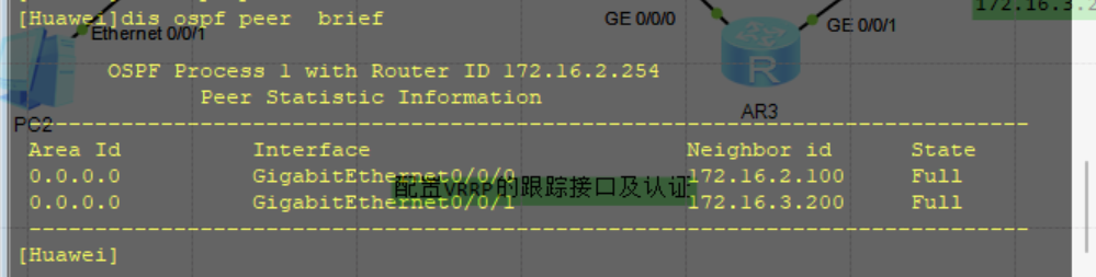
It can be observed that AR1 has successfully established OSPF neighbor relationship with AR2 and AR3 at this time
VRRP basic configuration
AR2:

interface GigabitEthernet0/0/0

 ip address 172.16.1.100 255.255.255.0

 vrrp vrid 1 virtual-ip 172.16.1.254

 vrrp vrid 1 priority 120

AR3:

interface GigabitEthernet0/0/0

 ip address 172.16.1.100 255.255.255.0

 vrrp vrid 1 virtual-ip 172.16.1.254
After configuration, view the VRRP information on AR2 and AR3 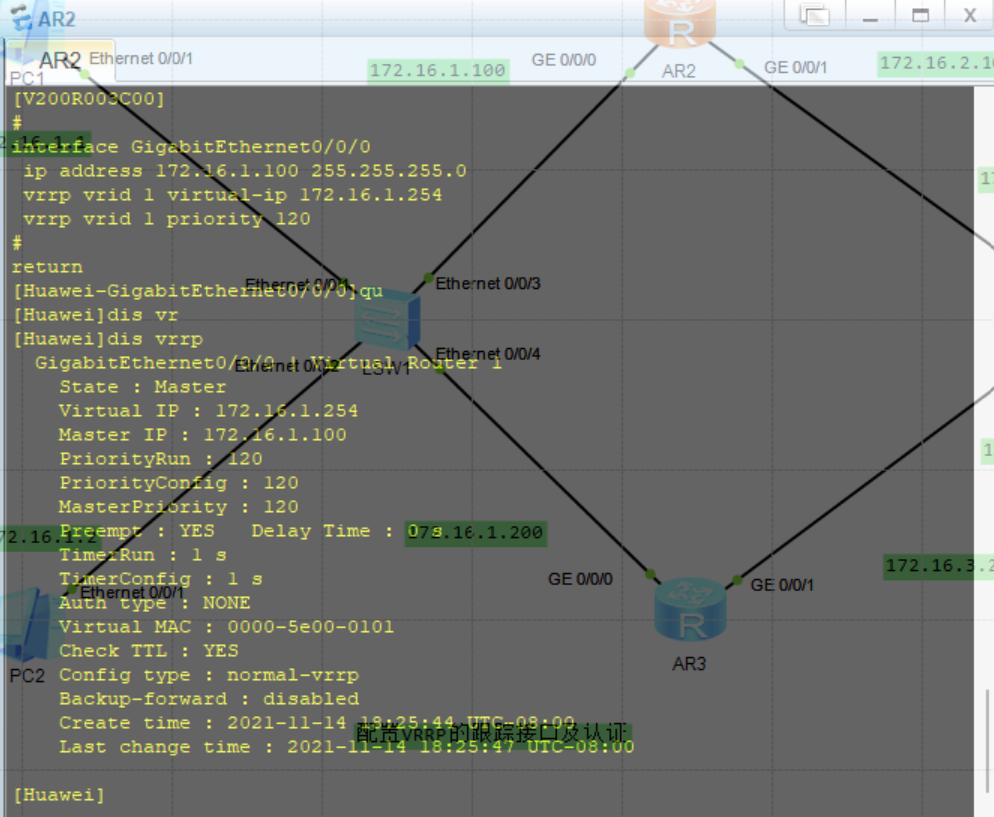
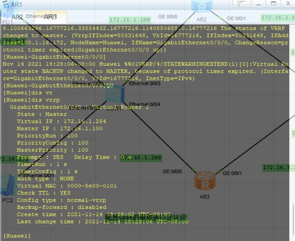 At this time, the network fails, and there is a problem with the link between AR2 and external router AR1,

After configuration, check the switching between active and standby;
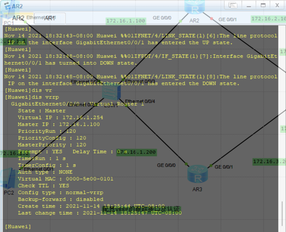
It is observed that the Master role of router AR2 has not been switched, and all traffic is still sent to AR2, so that users cannot access the external network at this time. The connectivity test is omitted here. That is, VRRP cannot complete the switching between active and standby equipment by sensing the failure of the uplink interface;
Configure uplink interface monitoring
In order to further improve the reliability and security of the network, it is necessary to configure the uplink interface monitoring of VRRP on the Master device AR2. When the uplink interface of AR2 fails, the priority will be automatically reduced, so that the Backup device can seize the Master role and take over the work to minimize the impact caused by network interruption.
Restore G0/0/0 interface on AR1 and configure uplink interface monitoring on AR2. Monitor the uplink interface G0/0/0. When this interface is disconnected, cut the priority 50 to 70, which is less than the priority 100 of AR3.


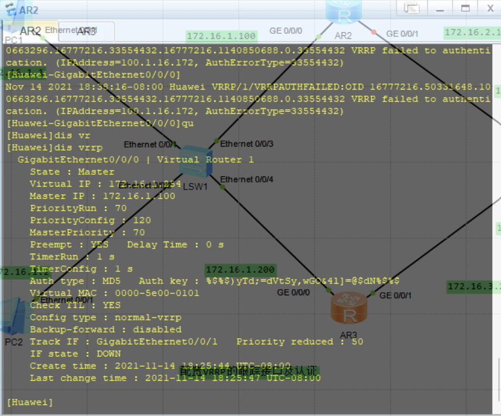
 After the configuration is completed, close the G0/0/0 interface of AR1, simulate the failure, and view the active / standby switching;
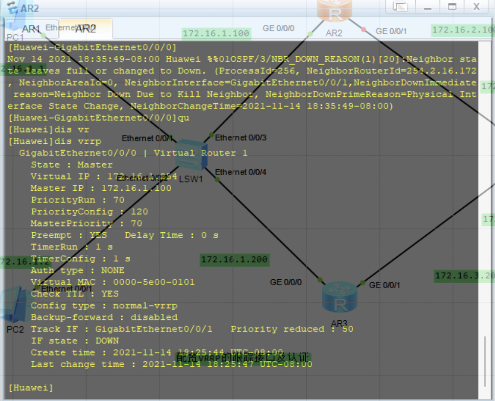
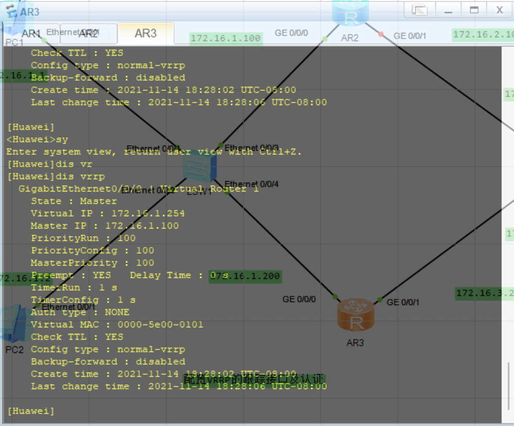
It can be observed that when the state of the specified interface monitored on AR2 is DOWN, the VRRP priority is cut off by 50 and becomes 70, which is less than the priority 100 of router AR3. Since the VRRP of AR3 defaults to the preemptive mode, it becomes Backup, AR3 becomes a new Master and continues the network forwarding. By default, when the monitored interface changes to DOWN, the value of VRRP priority decreases by 10;
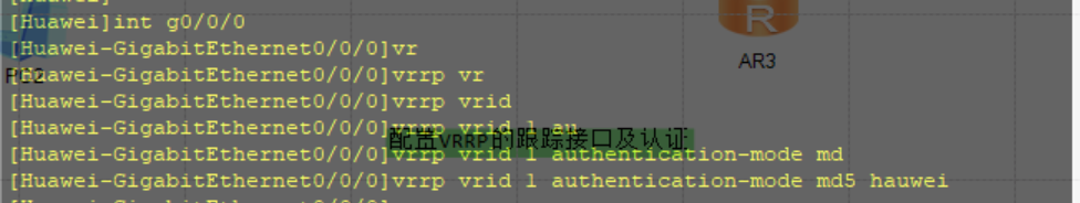
Configure VRRP authentication on AR2 and AR3
Configure interface authentication for VRRP virtual group 1 on AR2 and AR3. The authentication method is MD5 and the password is huawei.
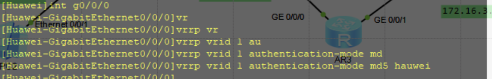
Note that when configuring VRRP message authentication, the authentication method of the same VRRP Backup group must be the same, otherwise the Master device and Backup device cannot negotiate successfully;
After configuration, view;
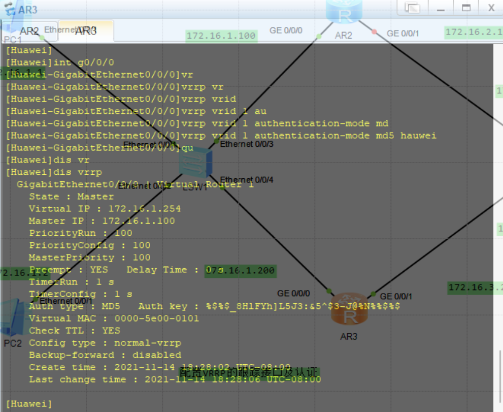
It can be observed that the authentication mode is configured successfully;
End of experiment;
Remarks: if there is any error, please understand!
This article is my study notes, for reference only! If repeated!!! Please contact me!