Modbus is a serial communication protocol and is widely used in industry.There is a lot of information about Modbus on the Internet, let's not go into details here.When I first came into contact, I looked at Modbus's introduction, just a few hundred pages of protocol introduction, as well as various commands and links layer applications. After a few days, the more confused I looked, the less useful I was.*
Finally, the Modbus protocol is not so complex after the successful transplantation on the single-chip computer. If you start learning, you do not have to understand every function of Modbus.Think of it as a simple serial protocol, using only the simplest few commands.Learn more about other functions after you become familiar with them.
The following is to understand the Modbus protocol from the point of view of single-chip serial communication, and how to port the protocol to the single-chip computer.
* Look at the Modbus protocol first
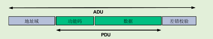
In general, the protocol consists of four parts: address, function, data, and validation.
Address 1 byte, that is, device address from 0 --- 255.
A function code is a command, but also a byte, ranging from 0 to 255.
Data bits have different lengths in different situations.
Check bits are typically used with CRC checks.
Let's see what the function codes are.
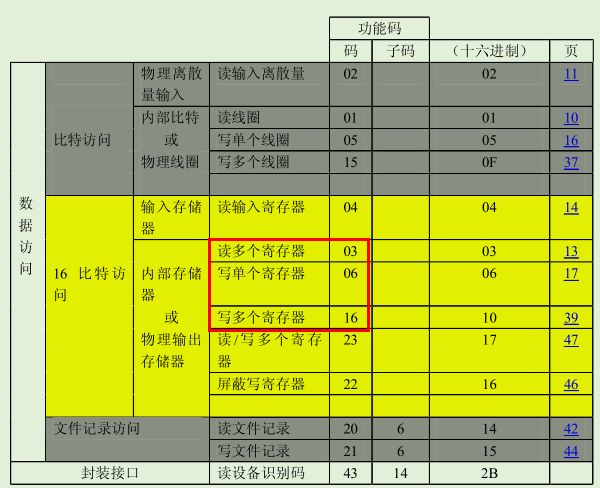
Common function codes are those on the table, which can be interpreted as a command represented by a number.Three commands, 03, 06 and 16, are enough when transplanting to single-chip computer.
Read coil, write single coil, write single register, etc. What is coil?What are registers?What do these mean?
Simple understanding of coils is bitwise operation.For example, the single-chip computer controls the output of 8 relays. In order to conveniently represent the status of the relay, 8 bits are used to represent the status of 8 relays, such as 0 to indicate the disconnection of the relay and 1 to indicate the suction of the relay.This means that all 8 relays are disconnected and that all 8 relays are sucked up by 0xFF.
Registers are byte operations, such as when a sensor collects temperature, using a byte to indicate the current temperature, such as the current temperature of 28 degrees C, using 0x1C.
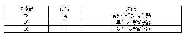
If you don't understand the meaning of register and coil, don't care about it. Treat him as a command. When using 03, 06, 16 in single-chip computer, these three commands will meet the basic needs. Here's a separate analysis of the meaning of these three commands.
03is to read multiple retention register values, the number of reads can be set, such as 8 sets of temperature sensors to collect data, to read temperature values, you can read one set of values, or read multiple values at one time, the number of reads can be set by yourself.
First look at the command format of 03
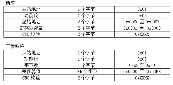
Request is data sent by single-chip computer host, and normal response is data returned from host when the command sent by host is in correct format.When the slave machine cannot recognize the data sent by the host correctly, the slave machine returns the exception response data and tells the host that there is an error in the command sent.
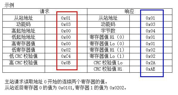
Explain the meaning of each bit in the command here. Here is the value of 8 sets of temperature sensors. If a slave receives 8 temperature sensors, the slave address is defined as 0x01, which can be defined by itself according to the actual project.The function code is 0x03, which uses the function code specified by Modbus to read multiple registers.The starting address is two bytes, which means to read data from the first temperature sensor, and the number of registers is two bytes, which means to read the values of several temperature sensors.Since there are only 8 temperature sensors, the starting address range is 0x0000 ---- 0x0007.The number of registers ranges from 0x0001 to 0x0008, reading the values of at least one register and up to eight registers.Finally, CRC checking. The specific way of checking CRC is not concerned here. Call the checking function directly when using it.
Note here that the starting address and the number of requests are sent when requesting data, and there are no requests when returning data, only the number of registers bytes sent.
For example, if you want to read the value of the first temperature sensor now, the request data format is as follows:
From Site Address Function Code High Start Address Low Start Address Low Register Number High Register Number Low CRC Check High CRC Check Low
0x01 0x03 0x00 0x00 0x00 0x01 xx xx
Starting at address 0, read the value of one register, that is, the value of the first temperature sensor.
The normal response return data format is as follows
From Site Address Function Code Bytes Register Number High Register Number Low CRC Check High CRC Check Low
0x01 0x03 0x02 0x00 0x1E XX XX
The values of two byte registers, 0x001E and 30 decimal digits corresponding to 0x001E, are read, indicating that the temperature value of the first temperature sensor is 30 C.
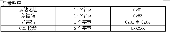
So what is an exception response used?If the data requested is sent by reading the value of the 9th temperature sensor and no 9th sensor is found after receiving the data from the host, indicating that the address value sent by the host exceeds the range, then the host will be sent an abnormal response from the machine.There are several common exception response codes
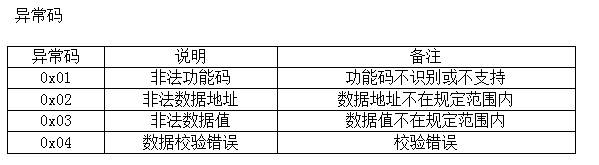
As you can see from the exception response code, the exception code whose address value is not in range is 0x02. When Modbus specifies that an exception response is returned, the error code value is the function code value plus 0x80, and the current function code is 0x03. Therefore, the error code value returned is 0x83 and the error code value is 0x02.
Request data:
From Site Address Function Code High Start Address Low Start Address Low Register Number High Register Number Low CRC Check High CRC Check Low
0x01 0x03 0x00 0x09 0x00 0x01 xx xx
Exception response:
Slave Address, Error Code, Exception Code, CRC Check
0x01 0x83 0x02 xx
Take another example of reading multiple register values:
Below you can see that 0x06 writes a single hold register, which writes data to a specified register.The communication format is as follows:
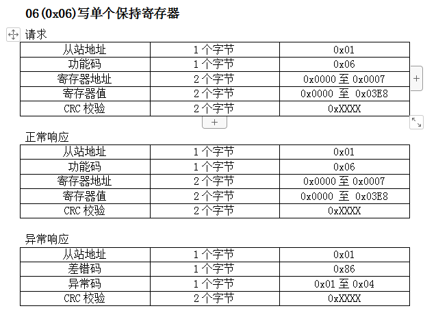
An example of communication is as follows:
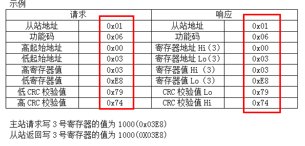
It is more understandable to see that the request command to write a single hold register is exactly the same as the normal response command.This block should note that the error code value is the function code value plus 0x80, the current function code is 0x06, so the error code value returned is 0x86.
Look at 16 (0x10) writing multiple hold registers, writing multiple save registers is basically the same as reading multiple registers, but one is reading and the other is writing.
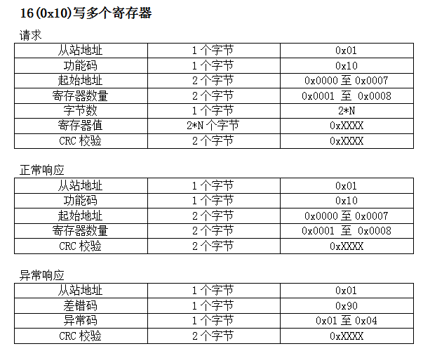
This block should note that the error code value is the function code value plus 0x80, the current function code is 0x10, so the error code value returned is 0x90.
An example of communication is as follows:
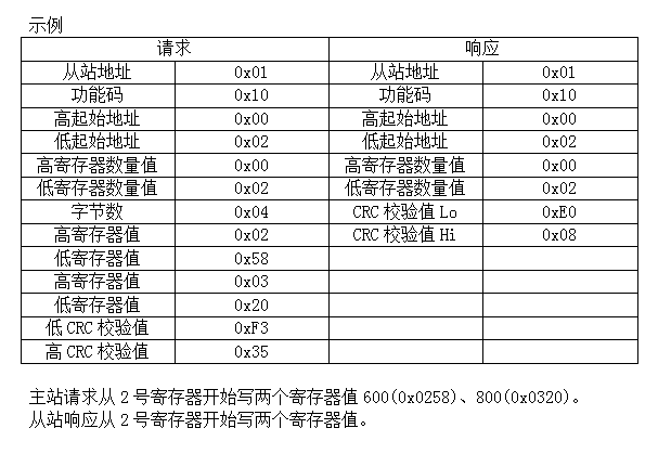
The response command only returns the number of registers written, not the value of the registers written. This is different from writing a single register.
From the above analysis, you can get a general idea of Modbus, which is not as complex as you might think.
Here's how you can implement the three commands above with code.
First look at the implementation of serial sending and receiving codes
#include "uart.h"
#include "stdio.h"
#include "main.h"

u8 ReceiveBuf[MaxDataLen] = {0};
u8 RecIndexLen = 0;
void Uart1_IO_Init( void )
{
    PD_DDR |= ( 1 << 5 ); //Output mode TXD
    PD_CR1 |= ( 1 << 5 ); //push-pull
    PD_DDR &= ~( 1 << 6 ); //Input mode RXD
    PD_CR1 &= ~( 1 << 6 ); //Floating Input
}
//The maximum baud rate can be set to 38400
void Uart1_Init( unsigned int baudrate )
{
    unsigned int baud;
    baud = 16000000 / baudrate;
    Uart1_IO_Init();
    UART1_CR1 = 0;
    UART1_CR2 = 0;
    UART1_CR3 = 0;
    UART1_BRR2 = ( unsigned char )( ( baud & 0xf000 ) >> 8 ) | ( ( unsigned char )( baud & 0x000f ) );
    UART1_BRR1 = ( ( unsigned char )( ( baud & 0x0ff0 ) >> 4 ) );
    UART1_CR2_bit.REN = 1;        //Receive Enables
    UART1_CR2_bit.TEN = 1;        //Send Enables
    UART1_CR2_bit.RIEN = 1;       //Receive interrupt enable
}
//Blocking Sender Function
void SendChar( unsigned char dat )
{
    while( ( UART1_SR & 0x80 ) == 0x00 ); //Send Data Register Empty
    UART1_DR = dat;
}
//Send a set of data
void Uart1_Send( unsigned char* DataAdd, unsigned char len )
{
    unsigned char i;
    for( i = 0; i < len; i++ )
    {
        SendChar( DataAdd[i] );
    }
    //SendChar(0x0d); //Send Enter Line Break, Test
    //SendChar(0x0a);
}
//Receive interrupt function interrupt number 18
#Pragma vector = 20 // IAR interrupt number, add 2 to STVD interrupt number
__interrupt void UART1_Handle( void )
{
    u8 res = 0;
    res = UART1_DR;
    ReceiveBuf[RecIndexLen++] = res;
    return;
}
The serial code is the same as the general usage, initializing the IO port and baud rate, then receiving data with interrupts, a ReceiveBuf array to store the received data, and RecIndexLen to count the length of the received data.
After a set of data has been received, the data processing function is called to process the received data.
//Processing received data
// Receive: [Address][Function Code][High Start Address][Low Start Address][High Total Registers][Low Total Registers][Low CRC][High CRC]
void DisposeReceive( void )
{
    u16 CRC16 = 0, CRC16Temp = 0;
    if( ReceiveBuf[0] == SlaveID )                                 //Address equals native address range: 1 - 32
    {
        CRC16 = App_Tab_Get_CRC16( ReceiveBuf, RecIndexLen - 2 );  //CRC Check Low Byte is the last byte of the message after the first high byte
        CRC16Temp = ( ( u16 )( ReceiveBuf[RecIndexLen - 1] << 8 ) | ReceiveBuf[RecIndexLen - 2] );
        if( CRC16 != CRC16Temp )
        {
            err = 4;                                               //CRC Check Error
        }
        StartRegAddr = ( u16 )( ReceiveBuf[2] << 8 ) | ReceiveBuf[3];
        if( StartRegAddr > 0x07 )
        {
            err = 2;                                               //Starting Address is not within the specified range for Channel 00 - 07 1 - 8
        }
        if( err == 0 )
        {
            switch( ReceiveBuf[1] )                                //Function Code
            {
                case 3:                                            //Read Multiple Registers
                {
                    Modbus_03_Slave();
                    break;
                }
                case 6:                                            //Write Single Register
                {
                    Modbus_06_Slave();
                    break;
                }
                case 16:                                           //Write multiple registers
                {
                    Modbus_16_Slave();
                    break;
                }
                default:
                {
                    err = 1;                                       //This function code is not supported
                    break;
                }
            }
        }
        if( err > 0 )
        {
            SendBuf[0] = ReceiveBuf[0];
            SendBuf[1] = ReceiveBuf[1] | 0x80;
            SendBuf[2] = err;                                      //Send error code
            CRC16Temp = App_Tab_Get_CRC16( SendBuf, 3 );           //Calculate CRC Checksum
            SendBuf[3] = CRC16Temp & 0xFF;                         //CRC Low
            SendBuf[4] = ( CRC16Temp >> 8 );                       //CRC High
            Uart1_Send( SendBuf, 5 );
            err = 0;                                               //Clear error flags after sending data
        }
    }
}
Data is parsed according to the Modbus protocol, and the first data is the address. Processing data starts when the address equals the local address, otherwise the data is not processed.If the address is correct, check that the check bits are correct, pass CRC checks on the data received, and then compare the calculated check bits with the received check bits. If the check bits are the same, the data received is correct, otherwise the data received is wrong and an exception code is returned.Next, read the starting address to check if it is in range.When the starting address is correct, the function code is read and the corresponding function is called according to the different function code.Finally, the exception response is handled and a set of exception response data is sent when the data received is incorrect.
Here's the function code handler
/*
Function function: Read-hold register 03
 Host Request Message: 0x01 0x03 0x0000 0x0001 0x840A Read a hold register starting from 0
 Normal response message from the station: The 2-byte data read from 0x01 0x03 0x02 0x09C4 0xBF87 is 0x09C4
*/
void Modbus_03_Slave( void )
{
    u16 RegNum = 0;
    u16 CRC16Temp = 0;
    u8 i = 0;
    RegNum = ( u16 )( ReceiveBuf[4] << 8 ) | ReceiveBuf[5];        //Get Number of Registers
    if( ( StartRegAddr + RegNum ) < 9 )                            //Register address + number of registers within specified range
    {
        SendBuf[0] = ReceiveBuf[0];
        SendBuf[1] = ReceiveBuf[1];
        SendBuf[2] = RegNum * 2;
        for( i = 0; i < RegNum; i++ )                              //Read values in hold registers
        {
            SendBuf[3 + i * 2] = HoldReg[StartRegAddr * 2 + i * 2];
            SendBuf[4 + i * 2] = HoldReg[StartRegAddr * 2 + i * 2 + 1];
        }
        CRC16Temp = App_Tab_Get_CRC16( SendBuf, RegNum * 2 + 3 );  //Get CRC Check Value
        SendBuf[RegNum * 2 + 3] = CRC16Temp & 0xFF;                //CRC Low
        SendBuf[RegNum * 2 + 4] = ( CRC16Temp >> 8 );              //CRC High
        Uart1_Send( SendBuf, RegNum * 2 + 5 );
    }
    else
    {
        err = 3;                                                   //The number of registers is not within the specified range
    }
}
If you are reading multiple register commands, you need to know the starting address and the number of registers to read. Since the starting address has already been calculated in the receive function, you only need to calculate the number of registers here.The data is then read from the retention register based on the starting address and the number of registers.Keep the register values stored in the HoldReg array, where the temperature values read by the temperature sensor are stored.Calculates the data check value to be sent after the register data has been read. The check value is calculated from the first data to the first bit before the check value by calling App_Tab_Get_CRC16() This function calculates the CRC check value.Finally, the read register data is returned.Through Uart1_The Send() function sends data.
Here is writing a single register
/*
Function function: Write a single hold register 06
 Home site request message: 0x01 0x06 0x0000 0x1388 0x849C Write number 0 register value 0x1388
 Normal response message from station: value of register 0x01 0x06 0x0000 x1388 0x849C 0 is 0x1388
*/
void Modbus_06_Slave( void )
{
    u16  RegValue = 0;
    u16 CRC16Temp = 0;
    RegValue = ( u16 )( ReceiveBuf[4] << 8 ) | ReceiveBuf[5];      //Get Register Value
    if( RegValue < 1001 )                                          //Register value not exceeding 1000
    {
        HoldReg[StartRegAddr * 2] = ReceiveBuf[4];                 //Storage Register Value
        HoldReg[StartRegAddr * 2 + 1] = ReceiveBuf[5];
        SendBuf[0] = ReceiveBuf[0];
        SendBuf[1] = ReceiveBuf[1];
        SendBuf[2] = ReceiveBuf[2];
        SendBuf[3] = ReceiveBuf[3];
        SendBuf[4] = ReceiveBuf[4];
        SendBuf[5] = ReceiveBuf[5];
        CRC16Temp = App_Tab_Get_CRC16( SendBuf, 6 );               //Get CRC Check Value
        SendBuf[6] = CRC16Temp & 0xFF;                             //CRC Low
        SendBuf[7] = ( CRC16Temp >> 8 );                           //CRC High
        Uart1_Send( SendBuf, 8 );
    }
    else
    {
        err =  3;                                                  //Register value is out of range
    }
}
This function is simple, just write the value of the register directly to the corresponding position of the register.
Finally, write multiple registers
/*
Function function: write multiple consecutive hold registers value 16
 Host Request Message: 0x01 0x10 0x7540 0x0002 0x04 0x0000 0x2710 xB731 Writes 2 hold registers starting from 0x7540 address for 4 bytes
 Normal response message from station: 0x01 0x10 0x7540 0x0002 0x5A10 Write two hold register values starting from 0x7540 address
*/
void Modbus_16_Slave( void )
{
    u16 RegNum = 0;
    u16 CRC16Temp = 0;
    u8 i = 0;
    RegNum = ( u16 )( ReceiveBuf[4] << 8 ) | ReceiveBuf[5];        //Get Number of Registers
    if( ( StartRegAddr + RegNum ) < 9 )                            //Register address + number of registers within specified range
    {
        for( i = 0; i < RegNum; i++ )                              //Storage Register Settings Value
        {
            HoldReg[StartRegAddr * 2 + i * 2] = ReceiveBuf[i * 2 + 7];
            HoldReg[StartRegAddr * 2 + 1 + i * 2] = ReceiveBuf[i * 2 + 8];
        }
        SendBuf[0] = ReceiveBuf[0];
        SendBuf[1] = ReceiveBuf[1];
        SendBuf[2] = ReceiveBuf[2];
        SendBuf[3] = ReceiveBuf[3];
        SendBuf[4] = ReceiveBuf[4];
        SendBuf[5] = ReceiveBuf[5];
        CRC16Temp = App_Tab_Get_CRC16( SendBuf, 6 );               //Get CRC Check Value
        SendBuf[6] = CRC16Temp & 0xFF;                             //CRC Low
        SendBuf[7] = ( CRC16Temp >> 8 );                           //CRC High
        Uart1_Send( SendBuf, 8 );
    }
    else
    {
        err = 3;                                                   //The number of registers is not within the specified range
    }
}
Write the corresponding value to the left register according to the address of the register. Since the starting address and the number of registers are both changing, we need to dynamically calculate the written register address here. Both the starting address and the number of registers are two. So we need to multiply by two in the calculation. If you don't understand this, we can calculate it by substituting a fixed value.
Now that Modbus is done with its protocol, take a look at the main function
while( 1 )
    {
        if( RecIndexLen_tem != RecIndexLen )            //Once data is received, clear the timer 0 times
        {
            RecIndexLen_tem = RecIndexLen;
            time_cnt = 0;
        }
        if( time_cnt > 5 )                              //Timing more than 5ms
        {
            if( RecIndexLen_tem > 0 )                   //Data length greater than 0 indicates receipt of data
            {
                RecIndexEnd = RecIndexLen;              //Store the length of the received data
                //Uart1_Send (ReceiveBuf, RecIndexEnd); //Send received data
                DisposeReceive();                       //Processing received data
                RecIndexLen = 0;
            }
            else                                        //No data received
            {
                time_cnt = 0;
            }
        }
    }
Since the Modbus protocol does not have a specified start and end flag, channel data cannot directly determine the start and end of a set of data.Time is used here to determine whether a set of data is received or not.The idea is to add 1 to the counter every milliseconds in the timer and clear the counter to zero if there is data in the serial port. If the serial port is receiving data all the time, the counter value will always be cleared.If the counter is not cleared when the serial port receives data, it will be accumulated all the time. When the counter is accumulated to a certain value, it means that there is no new data coming into the serial port during this time, then a set of serial port data receipt is considered complete.
RecIndexLen is the length of data received by the serial port. RecIndexLen_tem is the length of the last data received by the serial port. If these two values are not equal, the serial port receives new data, stores the new data length, and clears the counter.If there is no new data coming into the serial port all the time and the counter value is 5, it means that no new data is received by the 5ms serial port, then a set of data is considered complete and the data received is processed.This length of time is defined by the actual situation, and the reference standard is that it is longer than the interval between two bits.The longer the interval, the better considering line transmission and system delay.The longer the interval, the more accurate it will be to judge the completion of a set of data receipts, and the lower the likelihood of misjudgments.But it can't be too long, too long an interval will make the system respond slower.For example, when the baud rate is 9600, it takes about 0.83ms to send 9000/8=1200 bytes of data in one second.Five milliseconds is enough for this data interval.However, it is important to note that the sending interval between the two groups of data is also greater than 5ms, otherwise the data sending frequency is too high, and the data interval between the two groups is less than 5ms, so the program cannot tell when the receiving set of data ends, causing errors.
From the above analysis, it is not so difficult to see the Modbus protocol from the point of view of serial communication, as long as one of the function codes is learned to use, the use of other function codes will become simple.
Source Download Address Simple communication example of modbus protocol for STM8S003 single-chip computer