1, Introduction to CAN controller
STM32 comes with a basic extended CAN peripheral, also known as bxCAN. The features of bxCAN are as follows:
-
Support CAN protocol 2.0A and 2.0B active mode
-
Baud rate up to 1Mbps
-
Support time triggered communication
-
Has 3 send mailboxes
-
2 receive FIFO s with 3 levels of depth
-
Variable filter groups (also known as filter groups, up to 28)
CAN bus mode:
1. Working mode -
Initialization mode (INRQ=1, SLEEP=0)
-
Normal mode (INRQ=0, SLEEP=0)
-
Sleep mode (SLEEP=1)
2. Test mode
-
Silent mode (LBKM=0, SILM=1)
-
Loopback mode (LBKM=1, SILM=0)
-
Loopback silent mode (LBKM=1, SILM=1)
3. Debug mode
CAN controller block diagram: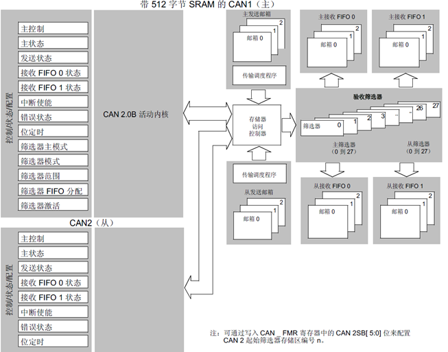
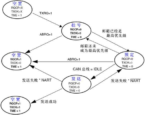
**CAN sending process: * * the program selects an empty mailbox (TME=1) - > sets the identifier (ID), data len gt h and sending data - > sets CAN_ TXRQ bit of tixr is 1, request sending - > mailbox registration (waiting to become the highest priority) - > scheduled sending (waiting for bus idle) - > sending - > mailbox vacancy.
CAN receiving process: FIFO empty - > receive valid message - > register_ 1 (a mailbox stored in FIFO, which is controlled by hardware and we don't need to pay attention to it) - > receive valid message - > register_ 2 - > receive valid message - > register_ 3 - > valid message received - > overflow.
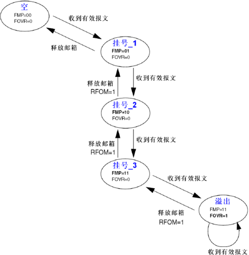
**Note: * * message FIFO has locking function (controlled by CAN_MCR and RFLM bit). After locking, new data will be discarded. If not locked, new data will replace old data
CAN bit timing of STM32: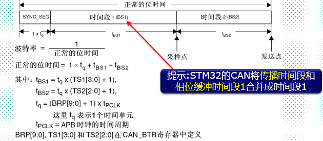
STM32F103,set up TS1=8,TS2=7,BRP=3,Baud rate=36000/[(9+8+1)*4]=500Kbps.
STM32F407,set up TS1=6,TS2=5,BRP=5,Baud rate=42000/[(7+6+1)*6]=500Kbps.
2, CAN register of STM32
1. CAN main control register (CAN#u MCR)
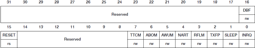
Set INRQ=0 to enable CAN to enter normal operation mode from initialization mode.
Set INRQ=1 to enable CAN to enter initialization mode from normal operation mode.
Note: During CAN initialization, first set INRQ=1 to enter the initialization mode for initialization (especially the setting of CAN_BTR, which must be set before CAN normal operation), and then set INRQ=0 to enter the normal operation mode.
2. CAN bit timing register (CAN_BTR)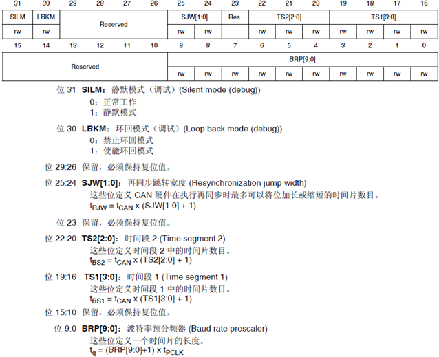
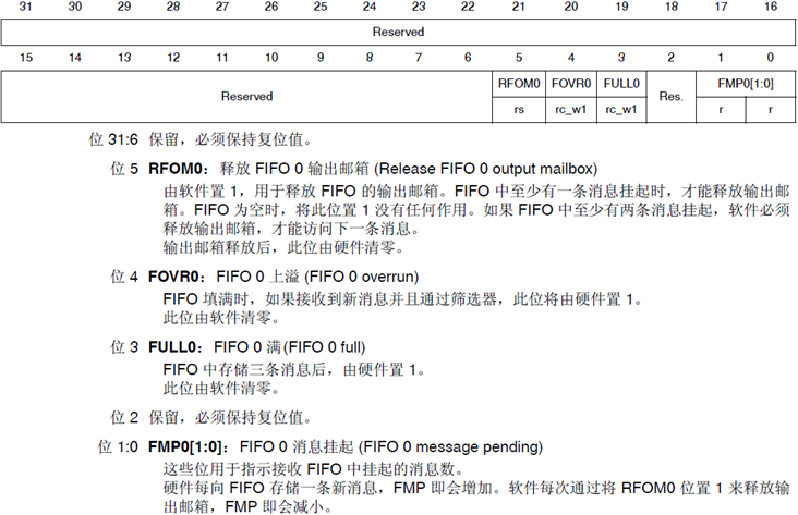
3. CAN receive FIFO register (CAN_RF0R\CAN_RF1R)
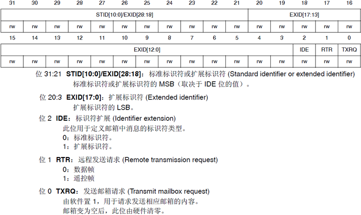
4. CAN send mailbox identifier register (CAN_TIxR, where x=0~2)
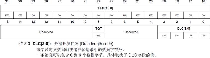
5. CAN send mailbox data length and timestamp register (CAN_TDTxR, where x=0~2)
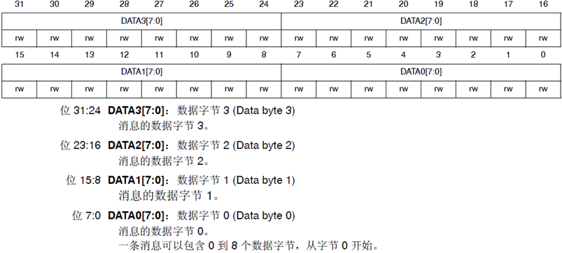
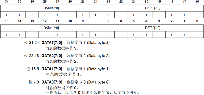
6. CAN send mailbox data register (CAN_TDLxR/CAN_TDHxR, where x=0~2)
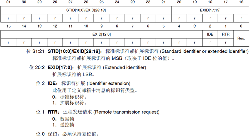
7. CAN receive FIFO mailbox identifier register (CAN_RIxR, where x=0/1)
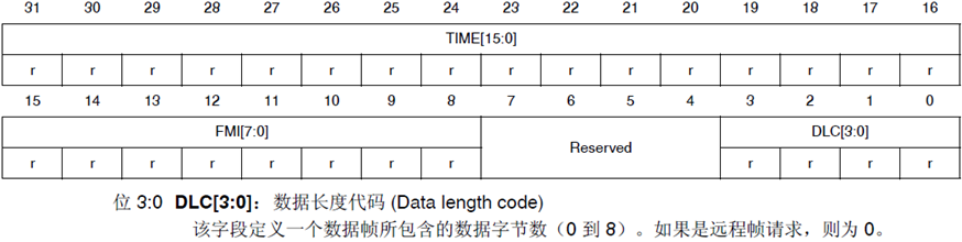
8. CAN receive FIFO mailbox data length and timestamp register (CAN_RDTxR, where x=0/1)
9. CAN receive FIFO mailbox data register (CAN_RDLxR/CAN_RDHxR, where x=0/1)
10. CAN filter mode register (CAN#u fm1r)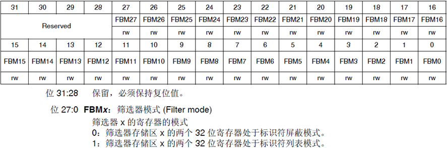
Note: this register sets the working mode of the filter, which must be configured when can(u fMR register FINIT=1. For STM32F103ZET6, only [13:0] bits are valid, and for interconnection STM32F1 or STM32F407, all are valid.
11. CAN filter scale register (CAN#u fs1r)
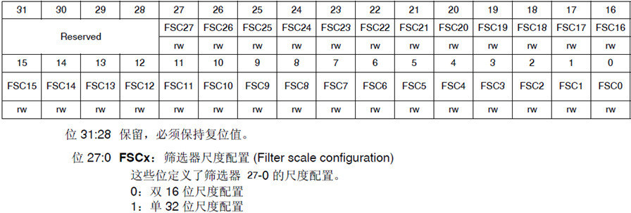
Note: this register is used to set the bit width of the filter. It must be configured when can(u fMR register FINIT=1. For STM32F103ZET6, only [13:0] bits are valid. For interconnection STM32F1 or STM32F407, all bits are valid.
12. CAN filter FIFO Association register (CAN#u ffa1r)
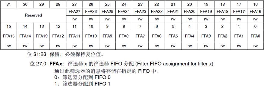
Note: this register sets the FIFO stored after the message passes through the filter group. If the corresponding bit is 0, it will be stored in FIFO0; if it is 1, it will be stored in FIFO1. This register can only be configured when the filter is in initialization mode (FINIT=1 of CAN_FMR register).
13. CAN filter activation register (CAN_FA1R)
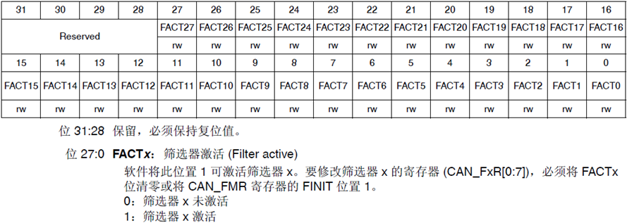
Note: this register is used to set the opening and closing of the filter group. For the corresponding position 1, the corresponding filter group is opened; set 0 to close the filter group.
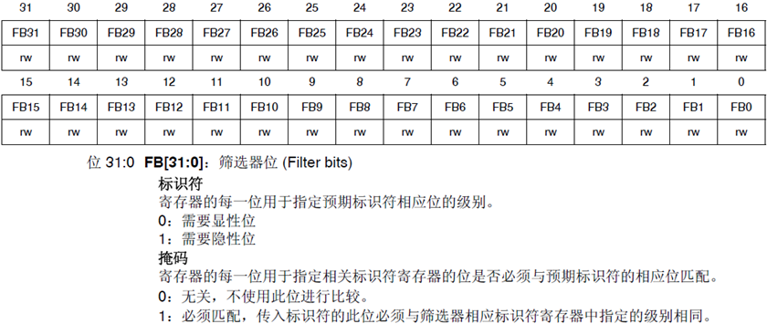
14. CAN filter group i register x (CAN_FiRx, where i=0~27, x=1/2)
3, CNA bus initialization process
- ① Configure the multiplexing function of relevant pins to enable the CAN clock.
To use CAN, first enable the clock of CAN. The clock of CAN is set through the 25th bit of APB1ENR. Secondly, set the relevant pin of CAN as multiplex output. Here, we need to set PA11 as pull-up input (CAN_RX pin) and PA12 as multiplex output (CAN_TX pin), and enable the clock of PA port - ② Set CAN working mode, baud rate, etc.
First set the INRQ bit of the CAN_MCR register to let the CAN enter the initialization mode, and then set other relevant control bits of the CAN_MCR. Then set the baud rate and working mode (normal mode / loopback mode) through the CAN_BTR.
Finally, set INRQ to 0 and exit the initialization mode. - ③ Set the filter.
We will use filter group 0 and work in 32-bit identifier mask bit mode. First set the FINIT bit of CAN_FMR to enter initialization mode, then set the working mode of filter group 0, identifier ID and mask bit. Finally, activate the filter and exit initialization mode.
4, Code display
//CAN initialization
//tsjw: resynchronize jump time unit. Range: CAN_SJW_1tq~ CAN_SJW_4tq
//tbs2: time unit of time period 2. Range: CAN_BS2_1tq~CAN_BS2_8tq;
//tbs1: time unit of time period 1. Range: CAN_BS1_1tq ~CAN_BS1_16tq
//brp: baud rate divider. Range: 1~1024; tq=(brp)*tpclk1
//Baud rate = Fpclk1/((tbs1+1+tbs2+1+1)*brp);
//mode:CAN_Mode_Normal, normal mode; CAN_Mode_LoopBack, loopback mode;
//The clock of Fpclk1 is set to 42M during initialization. If CAN1_Mode_Init(CAN_SJW_1tq,CAN_BS2_6tq,CAN_BS1_7tq,6,CAN_Mode_LoopBack) is set;
//Baud rate: 42M/((6+7+1)*6)=500Kbps
//Return value: 0, initialization OK;
//    Other, initialization failed;


u8 CAN1_Mode_Init(u8 tsjw,u8 tbs2,u8 tbs1,u16 brp,u8 mode)
{

  	GPIO_InitTypeDef GPIO_InitStructure;
	  CAN_InitTypeDef        CAN_InitStructure;
  	CAN_FilterInitTypeDef  CAN_FilterInitStructure;
#if CAN1_RX0_INT_ENABLE
   	NVIC_InitTypeDef  NVIC_InitStructure;
#endif
    //Enable correlation clock
	  RCC_AHB1PeriphClockCmd(RCC_AHB1Periph_GPIOA, ENABLE);//Enable PORTA clock

  	RCC_APB1PeriphClockCmd(RCC_APB1Periph_CAN1, ENABLE);//Enable CAN1 clock

    //Initialize GPIO
	  GPIO_InitStructure.GPIO_Pin = GPIO_Pin_11| GPIO_Pin_12;
    GPIO_InitStructure.GPIO_Mode = GPIO_Mode_AF;//Reuse function
    GPIO_InitStructure.GPIO_OType = GPIO_OType_PP;//Push pull output
    GPIO_InitStructure.GPIO_Speed = GPIO_Speed_100MHz;//100MHz
    GPIO_InitStructure.GPIO_PuPd = GPIO_PuPd_UP;//Pull up
    GPIO_Init(GPIOA, &GPIO_InitStructure);//Initialize PA11,PA12

	  //Pin multiplexing mapping configuration
	  GPIO_PinAFConfig(GPIOA,GPIO_PinSource11,GPIO_AF_CAN1); //GPIOA11 multiplexed to CAN1
	  GPIO_PinAFConfig(GPIOA,GPIO_PinSource12,GPIO_AF_CAN1); //GPIOA12 multiplexed to CAN1

  	//CAN unit settings
   	CAN_InitStructure.CAN_TTCM=DISABLE;	//Non time triggered communication mode
  	CAN_InitStructure.CAN_ABOM=DISABLE;	//Software automatic offline management
  	CAN_InitStructure.CAN_AWUM=DISABLE;//SLEEP mode wakes up through software (clear SLEEP bit of can - > MCR)
  	CAN_InitStructure.CAN_NART=ENABLE;	//Automatic message transmission is prohibited
  	CAN_InitStructure.CAN_RFLM=DISABLE;	//The message is not locked, and the new one overwrites the old one
  	CAN_InitStructure.CAN_TXFP=DISABLE;	//The priority is determined by the message identifier
  	CAN_InitStructure.CAN_Mode= mode;	 //Mode setting
  	CAN_InitStructure.CAN_SJW=tsjw;	//The resynchronization jump width (Tsjw) is tsjw+1 time unit CAN_SJW_1tq~CAN_SJW_4tq
  	CAN_InitStructure.CAN_BS1=tbs1; //Tbs1 range CAN_BS1_1tq ~CAN_BS1_16tq
  	CAN_InitStructure.CAN_BS2=tbs2;//Tbs2 range CAN_BS2_1tq~ 	 CAN_BS2_8tq
  	CAN_InitStructure.CAN_Prescaler=brp;  //The frequency division coefficient (Fdiv) is brp+1
  	CAN_Init(CAN1, &CAN_InitStructure);   // Initialize CAN1

		//Configure filter
 	  CAN_FilterInitStructure.CAN_FilterNumber=0;	  //Filter 0
  	CAN_FilterInitStructure.CAN_FilterMode=CAN_FilterMode_IdMask;
  	CAN_FilterInitStructure.CAN_FilterScale=CAN_FilterScale_32bit; //32 bit
  	CAN_FilterInitStructure.CAN_FilterIdHigh=0x0000;32 position ID
  	CAN_FilterInitStructure.CAN_FilterIdLow=0x0000;
  	CAN_FilterInitStructure.CAN_FilterMaskIdHigh=0x0000;//32-bit MASK
  	CAN_FilterInitStructure.CAN_FilterMaskIdLow=0x0000;
   	CAN_FilterInitStructure.CAN_FilterFIFOAssignment=CAN_Filter_FIFO0;//Filter 0 is associated to FIFO0
  	CAN_FilterInitStructure.CAN_FilterActivation=ENABLE; //Activate filter 0
  	CAN_FilterInit(&CAN_FilterInitStructure);//Filter initialization

#if CAN1_RX0_INT_ENABLE

	  CAN_ITConfig(CAN1,CAN_IT_FMP0,ENABLE);//FIFO 0 message registration interrupt allowed

  	NVIC_InitStructure.NVIC_IRQChannel = CAN1_RX0_IRQn;
  	NVIC_InitStructure.NVIC_IRQChannelPreemptionPriority = 1;     // The primary priority is 1
  	NVIC_InitStructure.NVIC_IRQChannelSubPriority = 0;            // The secondary priority is 0
  	NVIC_InitStructure.NVIC_IRQChannelCmd = ENABLE;
  	NVIC_Init(&NVIC_InitStructure);
#endif
	return 0;
}

#if CAN1_RX0_INT_ENABLE 	// Enable rx0 interrupt
//Interrupt service function
void CAN1_RX0_IRQHandler(void)
{
  	CanRxMsg RxMessage;
	int i=0;
    CAN_Receive(CAN1, 0, &RxMessage);
	for(i=0;i<8;i++)
	printf("rxbuf[%d]:%d\r\n",i,RxMessage.Data[i]);
}
#endif

//can sends a group of data (fixed format: ID 0X12, standard frame, data frame)
//len: data length (max. 8)
//msg: data pointer, maximum 8 bytes
//Return value: 0, successful;
//		 Others, failure;
u8 CAN1_Send_Msg(u8* msg,u8 len)
{
  u8 mbox;
  u16 i=0;
  CanTxMsg TxMessage;
  TxMessage.StdId=0x12;	 // The standard identifier is 0
  TxMessage.ExtId=0x12;	 // Set extension identifier (29 bits)
  TxMessage.IDE=0;		  // Use extended identifier
  TxMessage.RTR=0;		  // The message type is data frame, 8 bits per frame
  TxMessage.DLC=len;							 // Send two frames of information
  for(i=0;i<len;i++)
  TxMessage.Data[i]=msg[i];				 // First frame information
  mbox= CAN_Transmit(CAN1, &TxMessage);
  i=0;
  while((CAN_TransmitStatus(CAN1, mbox)==CAN_TxStatus_Failed)&&(i<0XFFF))i++;	//Wait for sending to end
  if(i>=0XFFF)return 1;
  return 0;

}
//can port receiving data query
//buf: data buffer;
//Return value: 0, no data received;
//		 Other, length of received data;
u8 CAN1_Receive_Msg(u8 *buf)
{
 	u32 i;
	CanRxMsg RxMessage;
    if( CAN_MessagePending(CAN1,CAN_FIFO0)==0)return 0;		//No data received, exit directly
    CAN_Receive(CAN1, CAN_FIFO0, &RxMessage);//Read data
    for(i=0;i<RxMessage.DLC;i++)
    buf[i]=RxMessage.Data[i];
	return RxMessage.DLC;
}