 http://www.armbbs.cn/forum.php?mod=viewthread&tid=108546
Chapter 3 Transplant ThreadX USBX protocol stack to STM32F407
This chapter explains the migration of USBX protocol stack to STM32F407.
catalogue
three point one Important tips for beginners
three point two USBX migration steps
3.2.1 Step 1, understand the overall design framework
3.2.2 Step 2, add USBX and USB driver to the project
3.2.3 Step 3, add project path
3.2.4 Step 4: do not drop or add some files
3.2.5 Step 4: configure GPIO and clock
3.2.6 Step 7, add the application code (USB interrupt, open and close USB flash disk)
3.3.1 Status function app_usb_device_thread_media_status
3.3.2 Read function app_usb_device_thread_media_read
3.3.3 Write function app_usb_device_thread_media_write
3.3.4 Interface function registration
three point four Use the MicroUSB interface and pay attention to the jumper cap setting
three point five Experimental routine
three point one Important tips for beginners
1, The software package specially provided by ST for STM32F4 used in this chapter: Download address
2, The supporting examples in this chapter use SD card to simulate a U disk and MicroUSB interface.
three point two USBX migration steps
The migration steps of ThreadX USBX are as follows:
3.2.1 Step 1, understand the overall design framework
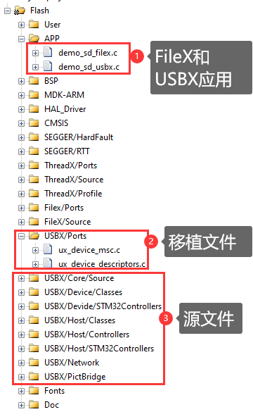
In order to facilitate transplantation, we need to have an overall understanding of the transplanted project:
3.2.2 Step 2, add USBX and USB driver to the project
Here, we add USBX files and USB driver files based on the template examples in the FileX tutorial. You can copy them directly from the examples provided in the tutorial in this chapter.
- Simulate USB flash drive file ux_device_msc.c/.h and ux_device_descriptors.c/.h is added to your project. The path is unlimited.
The supporting example is placed in the \ User\usb file.
- USB driver file stm32f4xx_hal_hcd.c,stm32f4xx_hal_pcd.c,stm32f4xx_hal_pcd_ex.c and stm32f4xx_ll_usb.c.
This is the HAL Library of STM32F4.
- USBX related source files.
You can copy all relevant documents into your own project. The supporting example is placed in \ USBX.
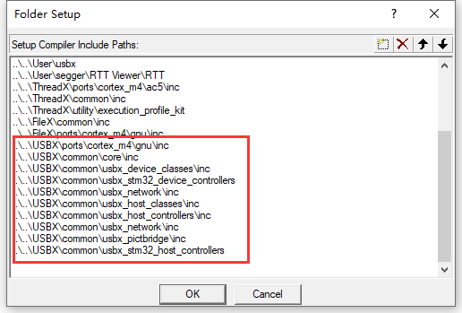
3.2.3 Step 3, add project path
You can add relevant paths according to the location of the source file you added:
3.2.4 Step 4: do not drop or add some files
The reason why you want to disable these files is that they need to use the NetXDUO network protocol stack, or you can not add them. The advantage of adding and then prohibiting is that you can add all when adding.
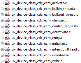
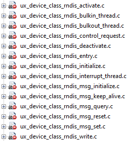
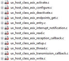
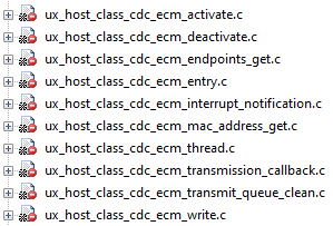
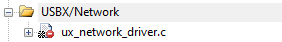
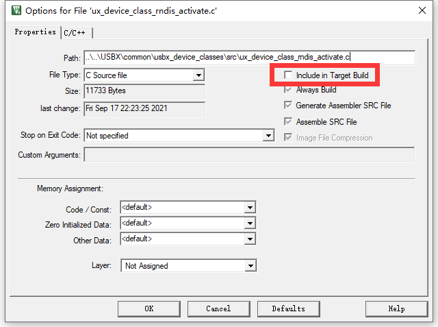
The prohibited method is to right-click the file and remove the following check:
3.2.5 Step 4: configure GPIO and clock
The USB clock is configured in the function systemclock of bsp.c file_ In config:
	/* The output voltage range of LDO regulator inside the chip is PWR_REGULATOR_VOLTAGE_SCALE1 */
	__HAL_RCC_PWR_CLK_ENABLE();
	__HAL_PWR_VOLTAGESCALING_CONFIG(PWR_REGULATOR_VOLTAGE_SCALE1);

	/* Enable HSE and select HSE as PLL clock source */
	RCC_OscInitStruct.OscillatorType = RCC_OSCILLATORTYPE_HSE;
	RCC_OscInitStruct.HSEState = RCC_HSE_ON;
	RCC_OscInitStruct.PLL.PLLState = RCC_PLL_ON;
	RCC_OscInitStruct.PLL.PLLSource = RCC_PLLSOURCE_HSE;
	RCC_OscInitStruct.PLL.PLLM = 25;
	RCC_OscInitStruct.PLL.PLLN = 336;
	RCC_OscInitStruct.PLL.PLLP = RCC_PLLP_DIV2;
	RCC_OscInitStruct.PLL.PLLQ = 7;  This frequency division is very important. The frequency division is 48 MHz
	if (HAL_RCC_OscConfig(&RCC_OscInitStruct) != HAL_OK)
	{
        Error_Handler(__FILE__, __LINE__);
	}
USB GPIO, NVIC initialization in demo_sd_usbx.c:
    /* Configure USB, GPIO, NVIC */
    {
        GPIO_InitTypeDef  GPIO_InitStruct = {0};

        __HAL_RCC_GPIOA_CLK_ENABLE();

		GPIO_InitStruct.Pin = GPIO_PIN_12|GPIO_PIN_11;
		GPIO_InitStruct.Mode = GPIO_MODE_AF_PP;
		GPIO_InitStruct.Pull = GPIO_NOPULL;
		GPIO_InitStruct.Speed = GPIO_SPEED_FREQ_HIGH;
		GPIO_InitStruct.Alternate = GPIO_AF10_OTG_FS;
		HAL_GPIO_Init(GPIOA, &GPIO_InitStruct);


        /* Enable USB FS clock */
        __HAL_RCC_USB_OTG_FS_CLK_ENABLE();


        /* Configure USB FS interrupt */
        HAL_NVIC_SetPriority(OTG_FS_IRQn, 0, 0);
        HAL_NVIC_EnableIRQ(OTG_FS_IRQn);
    }

    /* Initialize USB */
    {
		memset(&hpcd_USB_OTG_FS, 0x0, sizeof(PCD_HandleTypeDef));
	  hpcd_USB_OTG_FS.Instance = USB_OTG_FS;
	  hpcd_USB_OTG_FS.Init.dev_endpoints = 4;
	  hpcd_USB_OTG_FS.Init.speed = PCD_SPEED_FULL;
	  hpcd_USB_OTG_FS.Init.dma_enable = DISABLE;
	  hpcd_USB_OTG_FS.Init.phy_itface = PCD_PHY_EMBEDDED;
	  hpcd_USB_OTG_FS.Init.Sof_enable = DISABLE;
	  hpcd_USB_OTG_FS.Init.low_power_enable = DISABLE;
	  hpcd_USB_OTG_FS.Init.lpm_enable = DISABLE;
	  hpcd_USB_OTG_FS.Init.vbus_sensing_enable = DISABLE;
	  hpcd_USB_OTG_FS.Init.use_dedicated_ep1 = DISABLE;

        /* Initialize USB  */
        HAL_PCD_Init(&hpcd_USB_OTG_FS);

        /* Set TX FIFO and RX FIFO */
        HAL_PCDEx_SetRxFiFo(&hpcd_USB_OTG_FS, 128);
        HAL_PCDEx_SetTxFiFo(&hpcd_USB_OTG_FS, 0, 64);
        HAL_PCDEx_SetTxFiFo(&hpcd_USB_OTG_FS, 1, 128);

        /* Register STM32 to USBX protocol stack and initialize */
        status =  ux_dcd_stm32_initialize((ULONG)USB_OTG_FS, (ULONG)&hpcd_USB_OTG_FS);

        if (status != FX_SUCCESS)
        {
            return;
        }

    }
3.2.6 Step 7, add the application code (USB interrupt, open and close USB flash disk)
The USB operation is specially sorted into the file demo_sd_usbx.c. There are three main parts: open USB flash disk, close USB flash disk and USB interrupt service program. These three functions are basically universal. You can copy and paste them directly
Pay special attention to the USB interrupt service program. Don't forget to add it.
three point three USBX simulation USB flash disk migration interface file ux_device_msc.c Description
Here, the USBX underlying interface file UX_ device_ The implementation of MSC. C gives you a simple explanation.
3.3.1 Status function app_usb_device_thread_media_status
The code is as follows:
UINT  app_usb_device_thread_media_status(VOID *storage, ULONG lun, ULONG media_id, ULONG *media_status)
{

  /* The ATA drive never fails. This is just for app_usb_device only !!!! */
  return (UX_SUCCESS);
}
This function is mainly used to obtain the status of SD card analog U SB flash disk.
3.3.2 Read function app_usb_device_thread_media_read
The code is as follows:
/**
  * @brief  Function implementing app_usb_device_thread_media_read.
  * @param  storage : Not used
  * @param  lun: Logical unit number
  * @param  lba: Logical block address
  * @param  number_blocks: Blocks number
  * @param  data_pointer: Data
  * @param  media_status: Not used
  * @retval Status (0 : OK / -1 : Error)
  */
UINT  app_usb_device_thread_media_read(VOID *storage, ULONG lun,
                                       UCHAR *data_pointer,
                                       ULONG number_blocks,
                                       ULONG lba, ULONG *media_status)
{
#if 0
    UINT status = 0U;

    BSP_SD_ReadBlocks((uint32_t *) data_pointer, lba, number_blocks, 500);
    status = check_sd_status(0);
    return (status);

#else
	UINT status;
    if(check_sd_status(0) != BSP_ERROR_NONE)
    {

    }

    status = BSP_SD_ReadBlocks_DMA((uint32_t*)data_pointer, lba, number_blocks);

    if (status == BSP_ERROR_NONE)
    {
        if(tx_semaphore_get(&transfer_semaphore, DEFAULT_TIMEOUT) == TX_SUCCESS)
        {
            status = FX_SUCCESS;
        }
        else
        {
            status =  FX_BUFFER_ERROR;
        }
    }

    return status;
#endif
}
It is used to realize the reading function of SD analog U SB flash disk.
3.3.3 Write function app_usb_device_thread_media_write
The code is as follows:
/**
  * @brief  Function implementing app_usb_device_thread_media_write.
  * @param  storage : Not used
  * @param  lun: Logical unit number
  * @param  lba: Logical block address
  * @param  number_blocks: Blocks number
  * @param  data_pointer: Data
  * @param  media_status: Not used
  * @retval Status (0 : OK / -1 : Error)
  */
UINT  app_usb_device_thread_media_write(VOID *storage, ULONG lun,
                                        UCHAR *data_pointer,
                                        ULONG number_blocks,
                                        ULONG lba, ULONG *media_status)
{
#if 0
    UINT status = 0U;

    BSP_SD_WriteBlocks((uint32_t *) data_pointer, lba, number_blocks, 500);
    status = check_sd_status(0);

    return (status);

#else
	UINT status;

    if(check_sd_status(0) != BSP_ERROR_NONE)
    {

    }

    status = BSP_SD_ReadBlocks_DMA((uint32_t*)data_pointer, lba, number_blocks);

    if (status == BSP_ERROR_NONE)
    {
        if(tx_semaphore_get(&transfer_semaphore, DEFAULT_TIMEOUT) == TX_SUCCESS)
        {
            status = FX_SUCCESS;
        }
        else
        {
            status =  FX_BUFFER_ERROR;
        }
    }

#endif

    return status;
}
It is used to realize the write function of SD analog U SB flash disk.
3.3.4 Interface function registration
The interface function is registered in the demo file_ sd_ In usbx. C:
storage_parameter.ux_slave_class_storage_parameter_lun[0].ux_slave_class_storage_media_read  =  app_usb_device_thread_media_read;

storage_parameter.ux_slave_class_storage_parameter_lun[0].ux_slave_class_storage_media_write  =  app_usb_device_thread_media_write;

storage_parameter.ux_slave_class_storage_parameter_lun[0].ux_slave_class_storage_media_status =  app_usb_device_thread_media_status;
three point four Use the MicroUSB interface and pay attention to the jumper cap setting
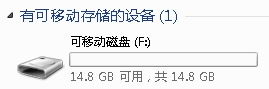
The example of migration in this week's tutorial simulates a U SB flash disk with internal RAM. The effect is as follows:
Note that the MicroUSB interface is used:
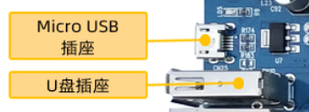
Pay attention to the setting of jumper cap at the lower left corner of the board:
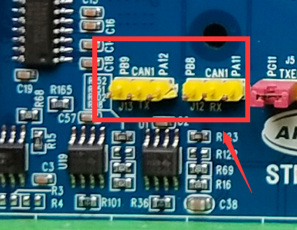
Here, it is used to select PB9 or PA12 pin for CAN1 TX and PB8 or PA11 pin for CAN1 RX. You can connect nothing here, or CAN1 TX is short circuited to PA12 through jumper cap, and CAN1 RX is short circuited to PA11 through jumper cap. Remember not to short-circuit PA12 and PA11 pins. USB should use these two pins.
three point five Experimental routine
Supporting examples:
V6-2401_ThreadX USBX Template
Purpose of the experiment:
- Learn USBX template and simulate U SB flash disk through SD.
Experiment content:
1. The following tasks are created. Press the key K1 to print the usage of the task stack through the serial port or RTT
========================================================
CPU utilization= 0.89%
Task execution time = 0.58645s
Idle execution time = 85.504470575s
Interrupt execution time = 0.173225395s
Total system execution time = 86.264180615s
=======================================================
Task priority task stack size current stack used Maximum stack usage Task name
Prio StackSize CurStack MaxStack Taskname
2 4092 303 459 App Task Start
5 4092 167 167 App Msp Pro
4 4092 167 167 App Task UserIF
5 4092 167 167 App Task COM
0 1020 191 191 System Timer Thread
Serial port software can use SecureCRT or H7-TOOL RTT to view print information.
App Task Start task : Start the task, which is used here as a BSP driver package.
App Task MspPro task: message processing.
App Task UserIF task: key message processing.
App Task COM task : Used here for LED flashing.
System Timer Thread task: system timer task
2. (1) all functions that use printf function pass through function App_Printf implementation.
(2) App_Printf function does semaphore mutually exclusive operation to solve the problem of resource sharing.
3. The default power on is to print information through the serial port. If RTT is used to print information
(1) MDK AC5, MDK AC6 or IAR can be defined as 1 by enabling the macro in bsp.h file
#define Enable_RTTViewer 1
(2) Embedded Studio continues to use this macro definition as 0 because Embedded Studio only makes RTT view of debugging status.
Experiment operation:
- Before testing, be sure to insert the SD card into the card holder in the upper left corner of the development board.
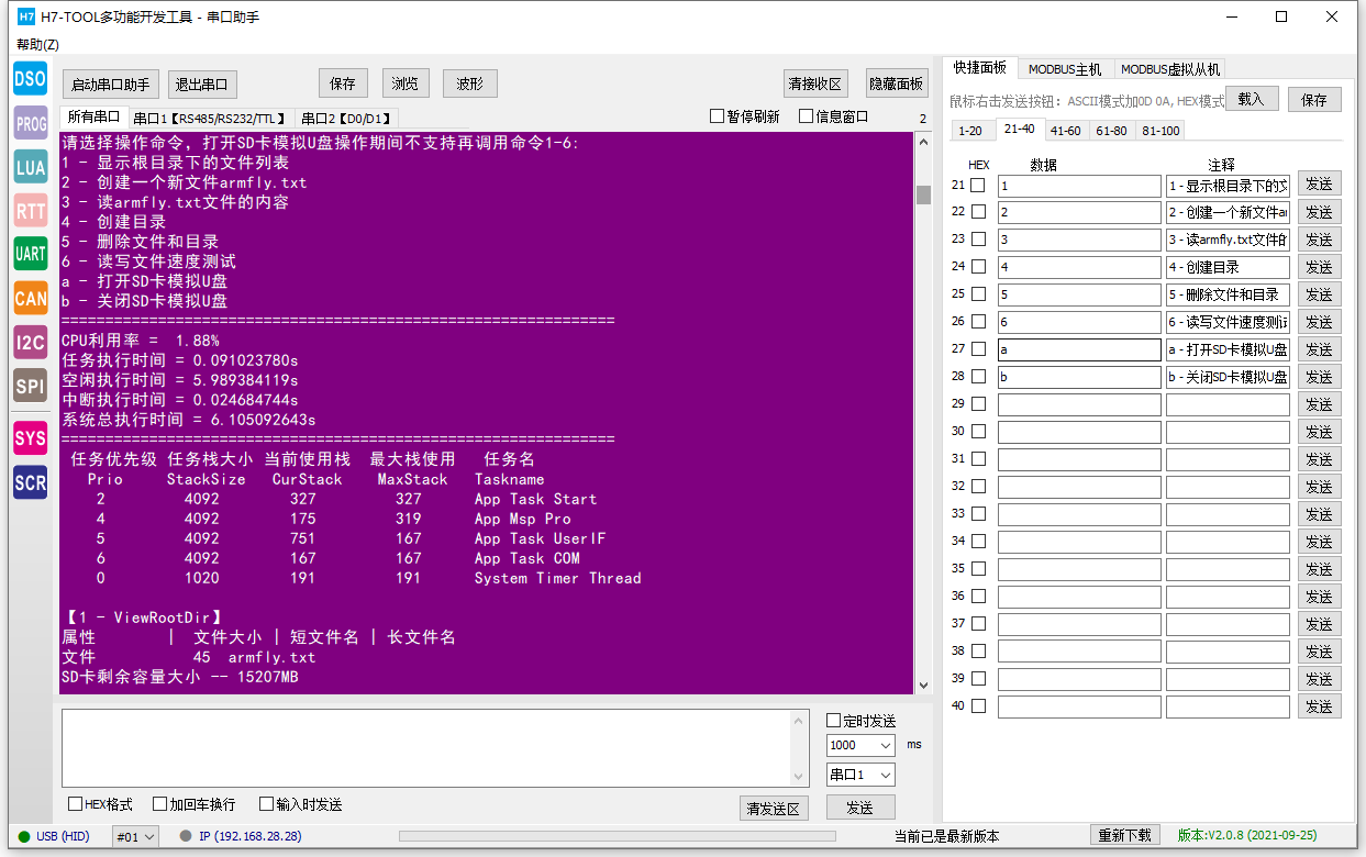
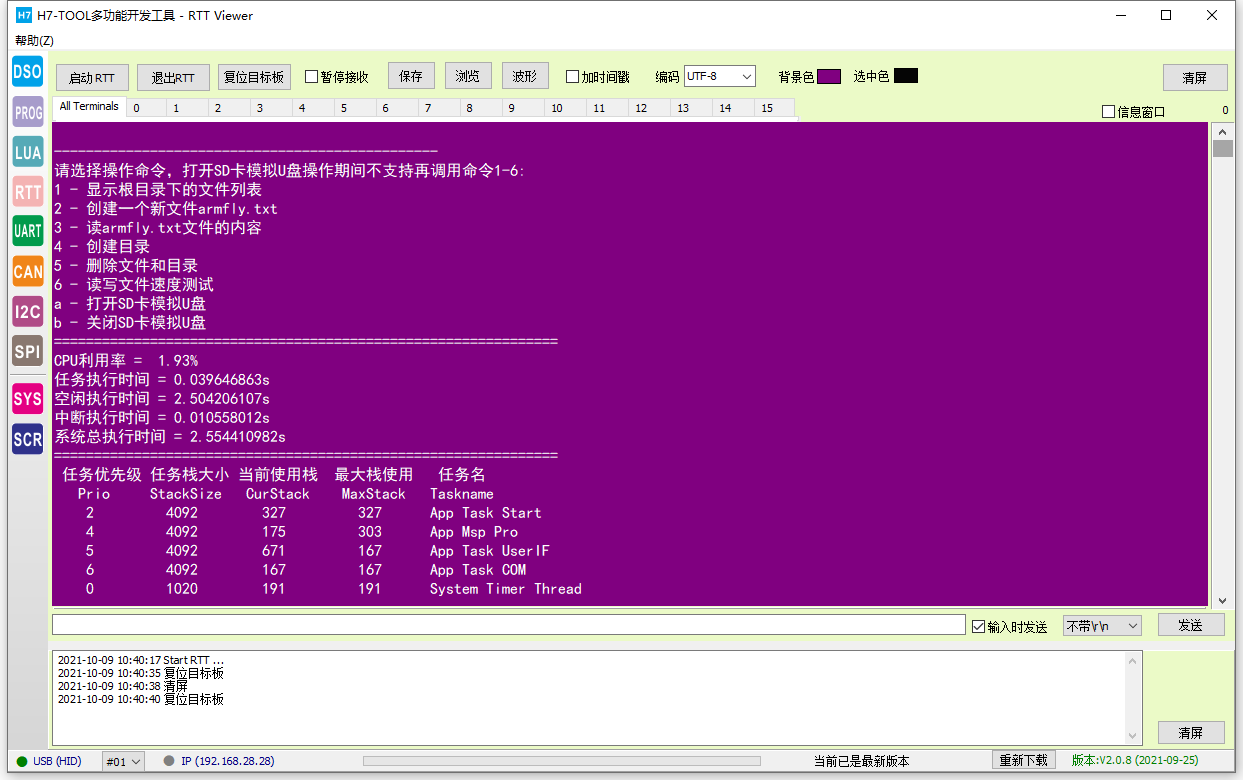
- The following six functions are supported. Users can send numbers 1-6 to the development board through the computer serial port software
- printf("1 - display the list of files under the root directory \ r\n");
- printf("2 - create a new file armfly.txt\r\n");
- printf("3 - read the contents of armfly.txt file \ r\n");
- printf("4 - Create directory \ r\n");
- printf("5 - delete files and directories \ r\n");
- printf("6 - read / write file speed test \ r\n");
- printf("a - Open SD card analog U SB flash disk \ r\n");
- printf("b - close SD card emulation U SB flash disk \ r\n");
Information printed by serial port:
Baud rate 115200, data bit 8, parity bit none, stop bit 1
RTT printing:
three point six summary
This chapter explains so much for you. Later chapters will explain the playing method of USBX in detail.