IIC Protocol
Summary of experimental code

IIC Protocol
IIC bus has three types of signals in the process of data transmission: start signal, end signal and response signal.Of these signals, the start signal is necessary, neither the end signal nor the response signal.At the same time, we also introduce its idle state, data validity, data transmission.
First, take a look at the IIC bus sequence diagram:
Start and stop signals
Start signal: Data line SDA jumps from high to low when clock line SCL is high; Start signal is a level jump time series signal, not a level signal;
Stop signal: When the clock line SCL is high, the data line SDA jumps from low to high; Stop signal is also a level jump time series signal, not a level signal.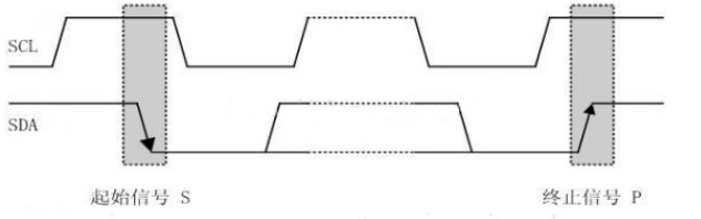
Answer signal
- For each byte (8 bit s) sent by the transmitter, the data line is released during the clock pulse 9, and an answer signal is fed back by the receiver.
- The response signal is at low level and is specified as a valid response bit (ACK), which means that the receiver has successfully received the byte.
- Answer signal is high level and is specified as non-response bit (NACK), which generally indicates that the receiver failed to receive the byte.
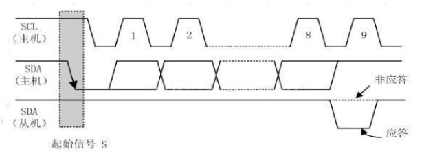
Requirements for feedback effective response bit ACK are that the receiver pulls down the data line SDA during the low level period before the 9th clock pulse and ensures a stable low level during the high level period of the clock.If the receiver is the master, after it receives the last byte, it sends a NACK signal to notify the controlled sender to end data transmission and release the data line SDA so that the master receiver can send a stop signal P.
Data validity
When IIC bus transmits data, the data on the data line must remain stable when the clock signal is at a high level; only when the signal on the clock line is at a low level, changes in the high or low level state on the data line are allowed.
That is, the data needs to be prepared before the clock line SCL rises.And it must be stable before the downward edge arrives.
Data communication
Each data transmitted on the IIC bus has a clock pulse corresponding (or synchronization control), that is, each bit of data is serially transmitted bit by bit on the SDA in conjunction with the SCL serial clock.The transmission of data bits is edge triggered.
Delay Time
IIC Bus Data Transfer
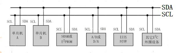
Each device on the IIC bus can act as a master or slave device, and each device corresponds to a unique address (the address is physically grounded or elevated), from which the master and slave devices determine which device to communicate with. In common applications, we use CPU modules with I2C bus interface as the master device and attach them to the bus.The other devices on the are used as slave devices.
That is, before transferring valid data, the master device must first specify the address of the slave device. The process of address assignment is the same as that of data transfer above, except that most of the slave device addresses are 7 bits, and then the protocol specifies that a minimum bit is added to the address to indicate the direction of data transfer next. 0 indicates that the master device writes data to the slave device and 1 indicates that the master device sends data to the slave device.Read data from the device.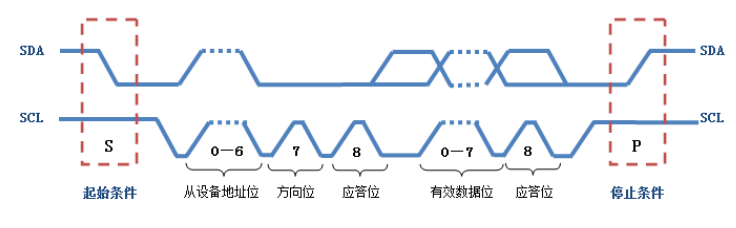
Write 1 byte, 1 byte has 8 bits, 1 bit write, cycle 8 times
//IIC sends a byte
//Return Slave Whether Answer
//1, there is a response
//0, no response
void IIC_Send_Byte(u8 txd)
{
    u8 t;
 SDA_OUT();
    IIC_SCL=0;//Lower Clock Start Data Transfer Lower Clock Can Change Data on SDA Line
    for(t=0;t<8;t++)   //8 bits per byte, to convert parallel data to serial data
    {
        //IIC_SDA=(txd&0x80)>>7;
  if((txd&0x80)>>7)   //Determine if the highest bit of data to be transmitted is 1
   IIC_SDA=1;    //Send 1 if 1 Send 0 if 0
  else
   IIC_SDA=0;
  txd<<=1;   //Move 8-bit parallel data to the left one bit
  delay_us(2);   //All three delays are required for TEA5767
  IIC_SCL=1;   //Data on SDA must be stable before the SCL rises and rises.
  delay_us(2);
  IIC_SCL=0;
  delay_us(2);
    }
}
Read 1 byte, 1 byte has 8 bits of data, read one bit, cycle 8 times
//Read 1 byte, ack=1, send ACK, ack=0, send nACK
u8 IIC_Read_Byte(unsigned char ack)
{
 unsigned char i,receive=0;
 SDA_IN();//SDA set as input
    for(i=0;i<8;i++ )   //8 bits per byte, read out serial one bit
 {
        IIC_SCL=0;
        delay_us(2);
  IIC_SCL=1;
        receive<<=1;       //Before each read, move the data left to turn serial data into parallel data
        if(READ_SDA)receive++;   //Read Current Bit If READ_SDA=1 then the current bit changes from 0 to 1
  delay_us(1);
    }
//After reading a byte of data, decide whether to send a response signal or not
    if (!ack)
        IIC_NAck();//Send nACK
    else
        IIC_Ack(); //Send ACK
    return receive;
}
Reads a byte of data from the device, a byte has 8 bits
//Read a data at the specified address at AT24CXX
//ReadAddr: Address to start reading
//Return value: read data
u8 AT24CXX_ReadOneByte(u16 ReadAddr)   //Our CPU and AT24Cxx communicate on this chip. The CPU is equivalent to the main device and the IIC is equivalent to the slave device.
{
 u8 temp=0;
    IIC_Start();
 if(EE_TYPE>AT24C16)   //EE_TYPE is the signal chip of memory#define EE_TYPE AT24C02
 {
  IIC_Send_Byte(0XA0);    //The main device sends the address first, usually 7 bits. Add 0 or 1 to the last bit to indicate the direction of transmission, 0 means write command, write data from the device, 1 means read command, read data from the device
  IIC_Wait_Ack();
  IIC_Send_Byte(ReadAddr>>8);//Send high address
  IIC_Wait_Ack();
 }else
 {
  IIC_Send_Byte(0XA0+((ReadAddr/256)<<1));   //Send device address 0XA0, write data
 }
 IIC_Wait_Ack();
   IIC_Send_Byte(ReadAddr%256);   //Send low address 2^8=256 ReadAddr%256 to take the lower eight bits of ReadAddr
 IIC_Wait_Ack();
 IIC_Start();  //Start signal
 IIC_Send_Byte(0XA1);           //Enter receive mode last bit 1 means read data from device
 IIC_Wait_Ack();
    temp=IIC_Read_Byte(0);    //A parameter of 0 means no answer signal
    IIC_Stop();//Produce a stop condition
 return temp;
}
Write one byte of data from the device (base address + offset address), one byte has 8 bits
//Write a data at the specified address at AT24CXX
//WriteAddr: Destination address for writing data
//DataToWrite: Data to be written
void AT24CXX_WriteOneByte(u16 WriteAddr,u8 DataToWrite)
{
    IIC_Start();
 if(EE_TYPE>AT24C16)
 {
  IIC_Send_Byte(0XA0);     //Send Write Command Here 0xA0 means 1010 0000 is the address of the device 24C02 of the IC device. The first 7 bits are all addresses, and the last 0 bits indicate the write operation to the slave device.
  IIC_Wait_Ack();
  IIC_Send_Byte(WriteAddr>>8);//Send high address
  }else
 {
  IIC_Send_Byte(0XA0+((WriteAddr/256)<<1));   //Send device address 0XA0, write data
 }
 IIC_Wait_Ack();
    IIC_Send_Byte(WriteAddr%256);   //Send low address
 IIC_Wait_Ack();
 IIC_Send_Byte(DataToWrite);     //Send Bytes
 IIC_Wait_Ack();
    IIC_Stop();//Produce a stop condition
 delay_ms(10);
}
Specifically, from the device, write/read a certain length of data, write/read a certain number of data, specific code reference experiment 23 IIC (warship plate STM32F103ZET6 library function developer source code)

