Based on HAL library, this paper realizes the transplantation of uCOS by using STM32CubeMX software and STM32F103C8T6 software.
1, CubeMX establishes STM32F103C8T6HAL Library
For details about the use of CubeMX here, please refer to my previous articles. Here you can operate directly without too much introduction. Installation and lighting of stm32CubeMX
1. Configure clock source
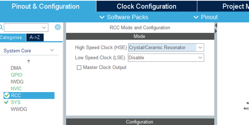
As shown in the figure, select RCC in the System Core and configure the high-speed clock source Crystal/Ceramic Resonator
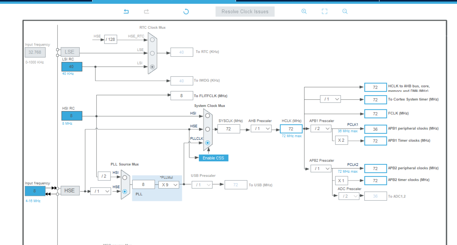
Here, the clock rate is set to 72MHz.
2. Configure the system
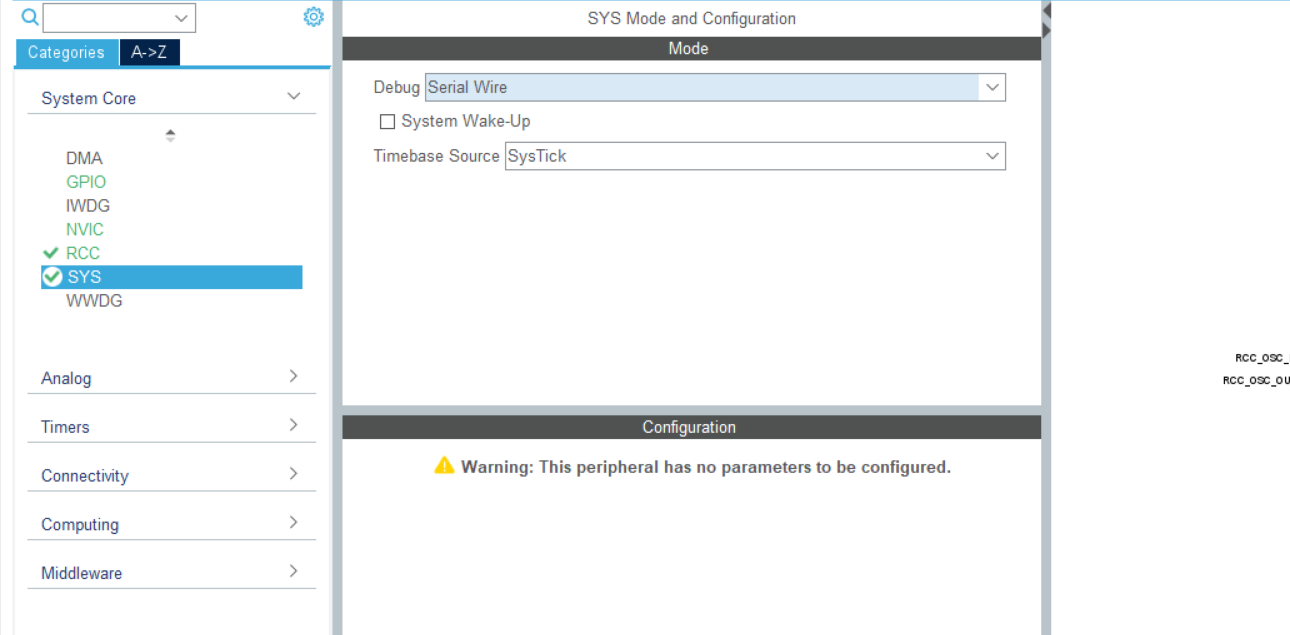
Select Serial Wire in SYS Debug.
3. Configure pins and serial ports
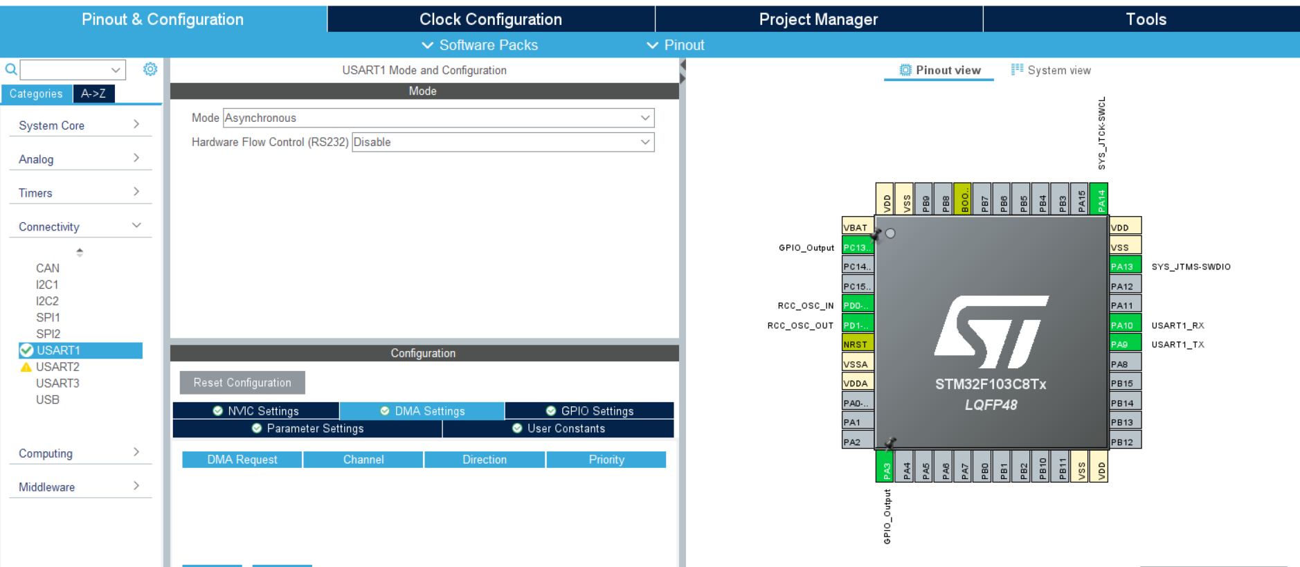
As shown in the figure, click USART in Connectivity and set the Mode to Asynchronous.
Here we use PC13 pin and PA3 pin, so set GPIOB0 pin and GPIOC13 pin to GPIO_Output.
4. Generate project
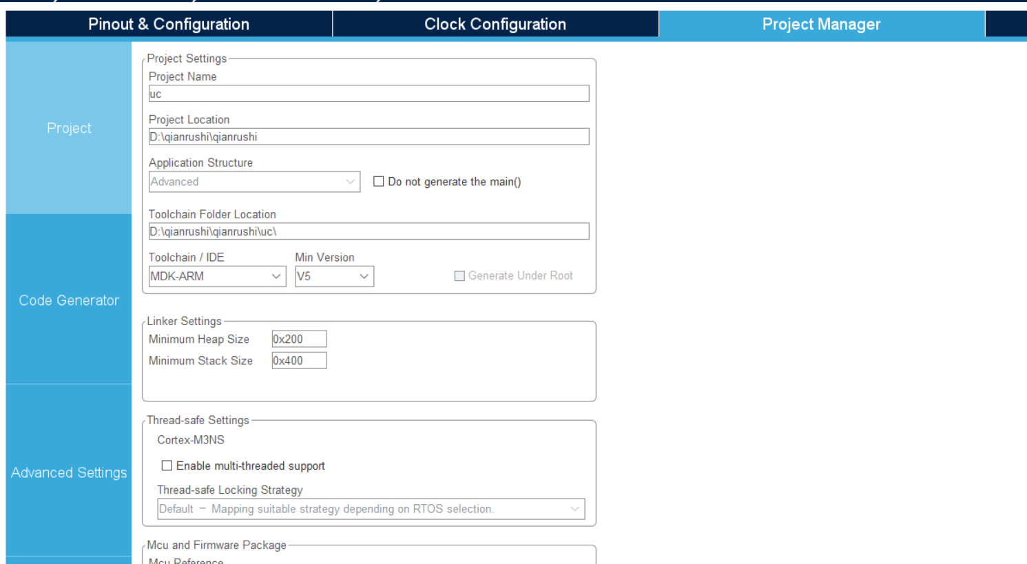
After configuring the relevant systems and parameters, select your project save path and generate the project.
2, Preparation before transplantation
1. Prepare uCOSIII source code
Download the source code on the official website http://micrium.com/downloadcenter/
However, the download speed on the official website is slow. Here is the online disk link:
https://pan.baidu.com/s/10RqsDRecbmVteWmDv2oUNQ
Extraction code: 1234
After decompressing the compressed package, there are the following four folders:

2. Create a new folder and add content
First, create two new folders in the same directory as the four folders under the Software folder mentioned above. As shown in the figure:
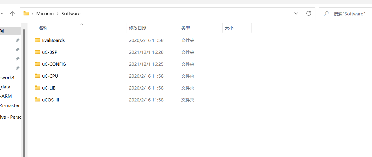
In the figure above, UC config and UC BSP are new folders.
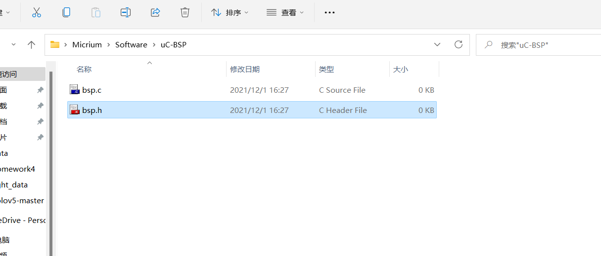
Create two empty files of bsp.c and bsp.h in UC BSP folder, as shown in the figure:
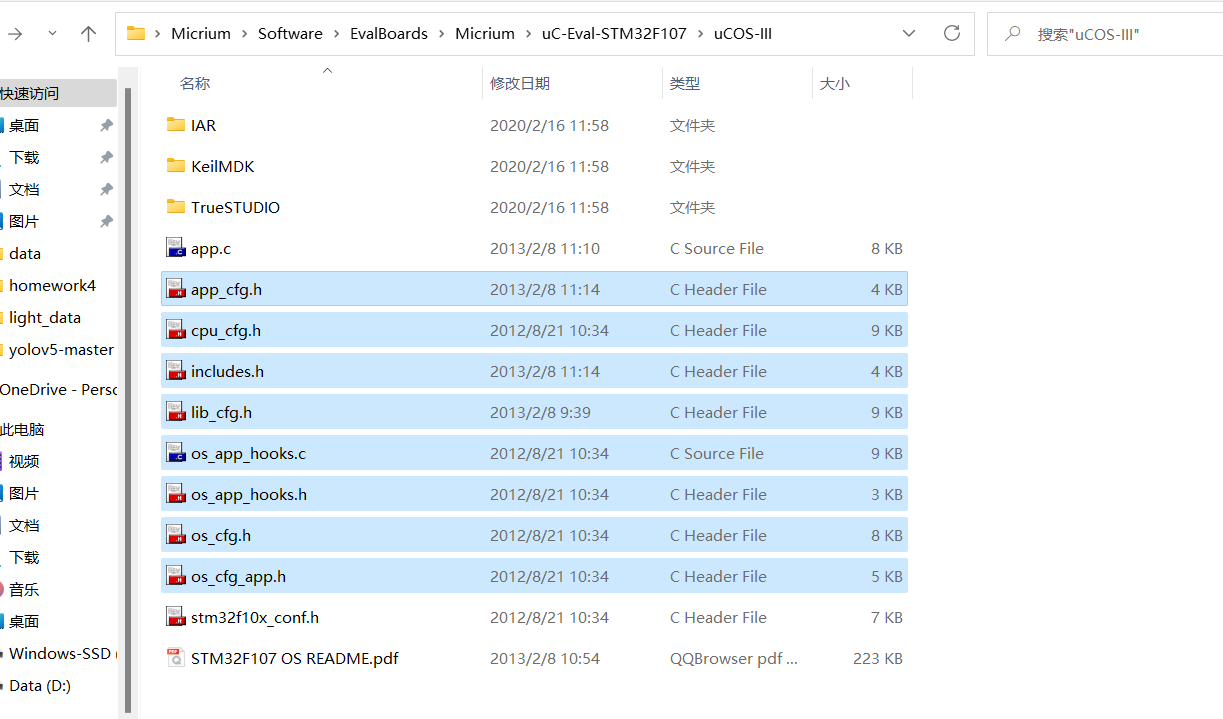
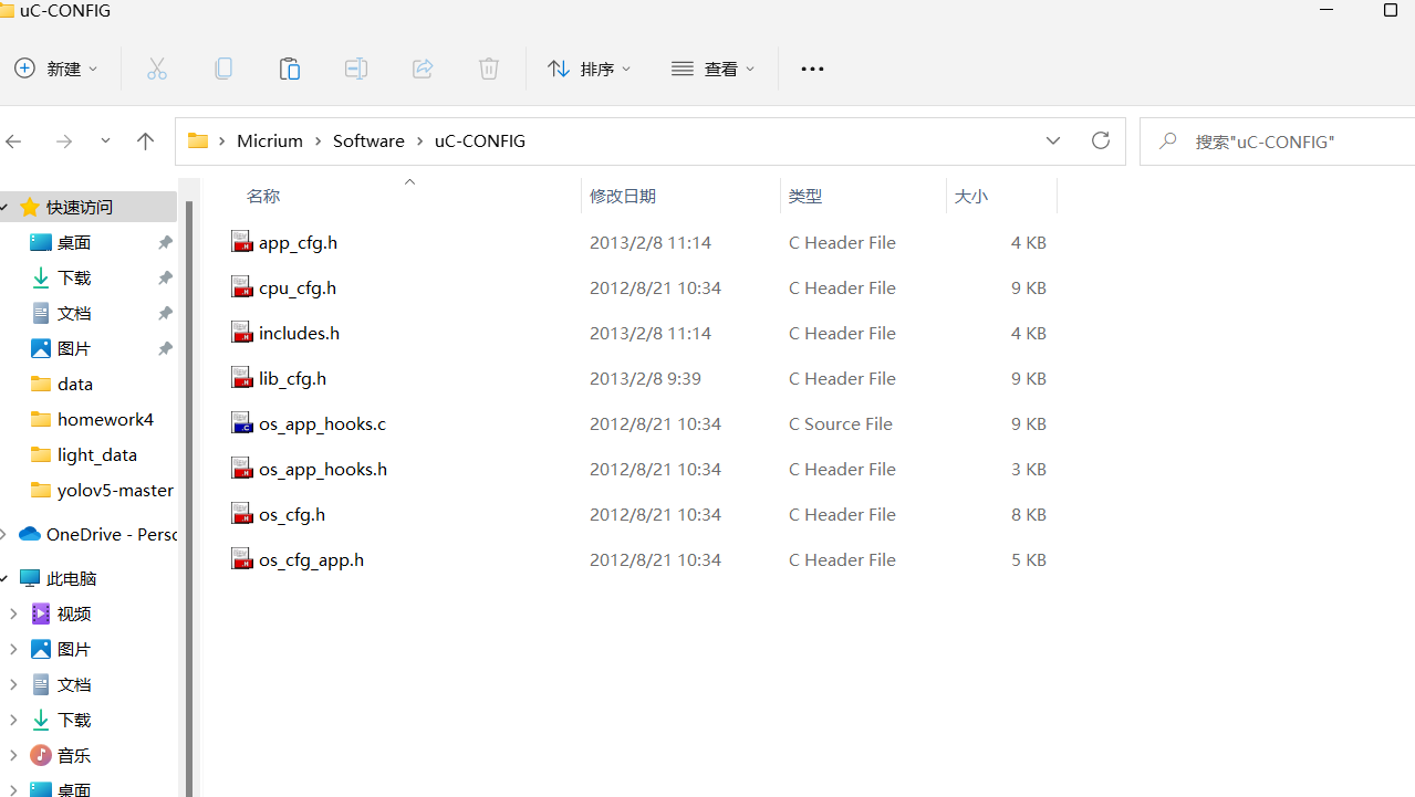
First enter the folder according to the path shown in the figure, then copy the eight files shown in the figure, return to the UC config folder we just created, and paste here:
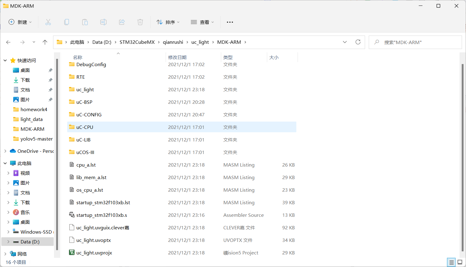
Then copy the five folders together and copy them under the MDK-ARM project file just generated by CubeMX:
3, Start migration
Open the project with Keil.
1. Add file to directory
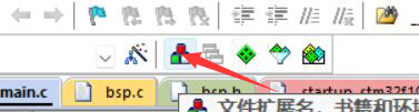
Click the button as shown in the figure:
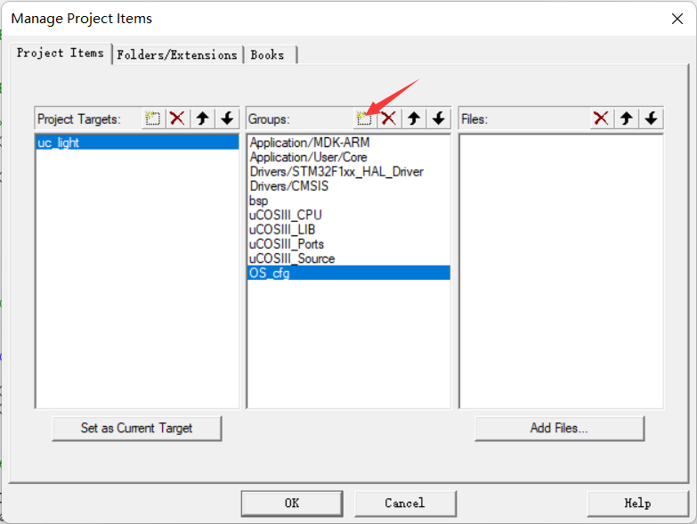
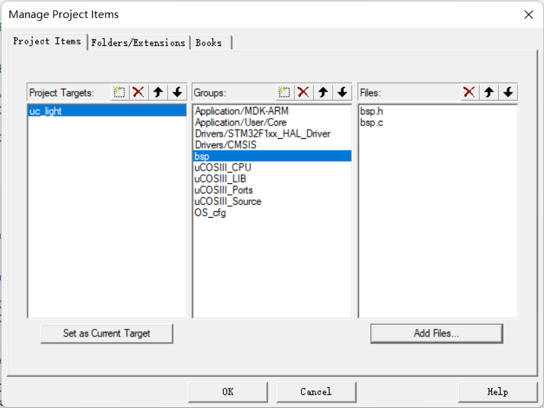
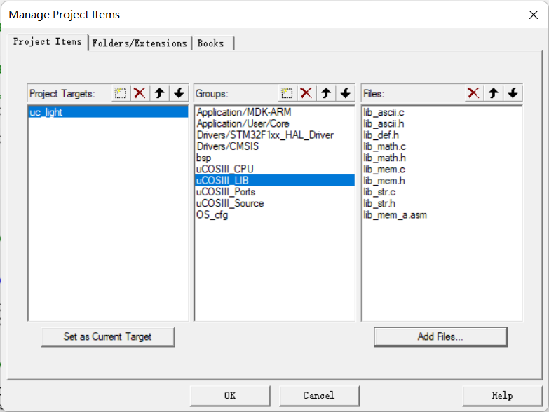
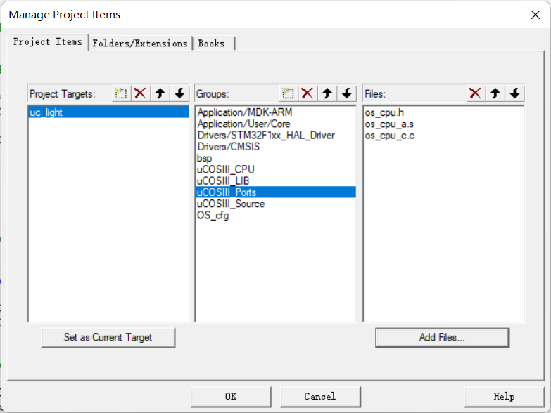
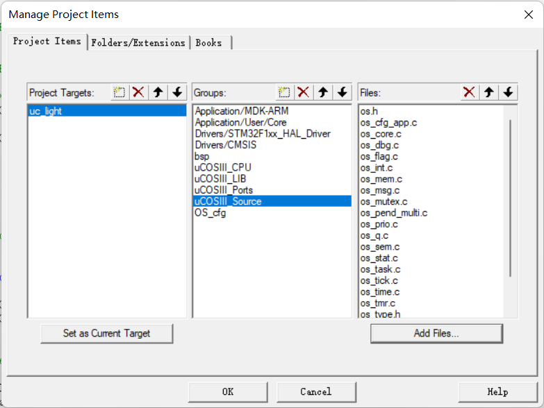
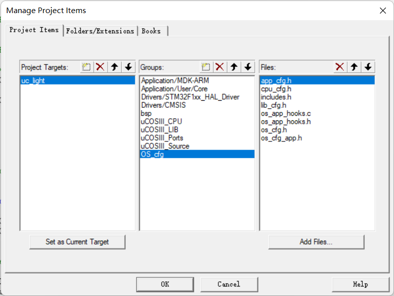
Click the button as shown in the figure in Groups to add the following 6 new Groups with group names:
Then select the group name and click Add Files on the right to Add Files
① Add two new blank files in UC bsp:
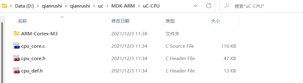
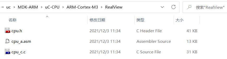
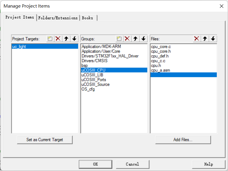
② In uCOSII_ Add three files in MDK arm \ UC CPU and three files in MDK arm \ UC CPU \ arm Cortex-M3 \ RealView path to the CPU group
③ In uCOSII_ Add nine files under MDK arm \ UC lib path and one file under MDK arm \ UC lib \ ports \ arm Cortex-M3 \ RealView path in lib group, a total of ten files.
④ In uCOSII_ Add three files in the MDK-ARM\uCOS-III\Ports\ARM-Cortex-M3\Generic\RealView path in the ports group.
⑤ In uCOSII_ Add twenty files in the MDK-ARM\uCOS-III\Source path in the source group.
⑥ On OS_ Add eight files in the MDK arm \ UC config path in the CFG group.
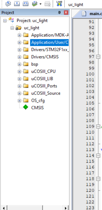
OK, the directory structure will change after the complete addition, as shown in the figure:
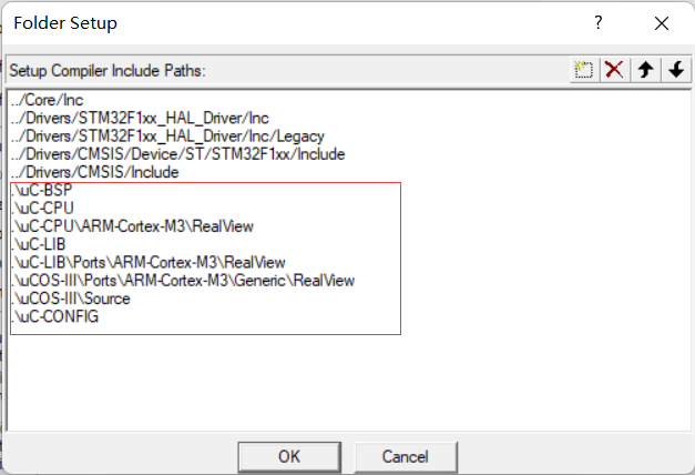
2. Add header file path
Click in sequence as shown below:
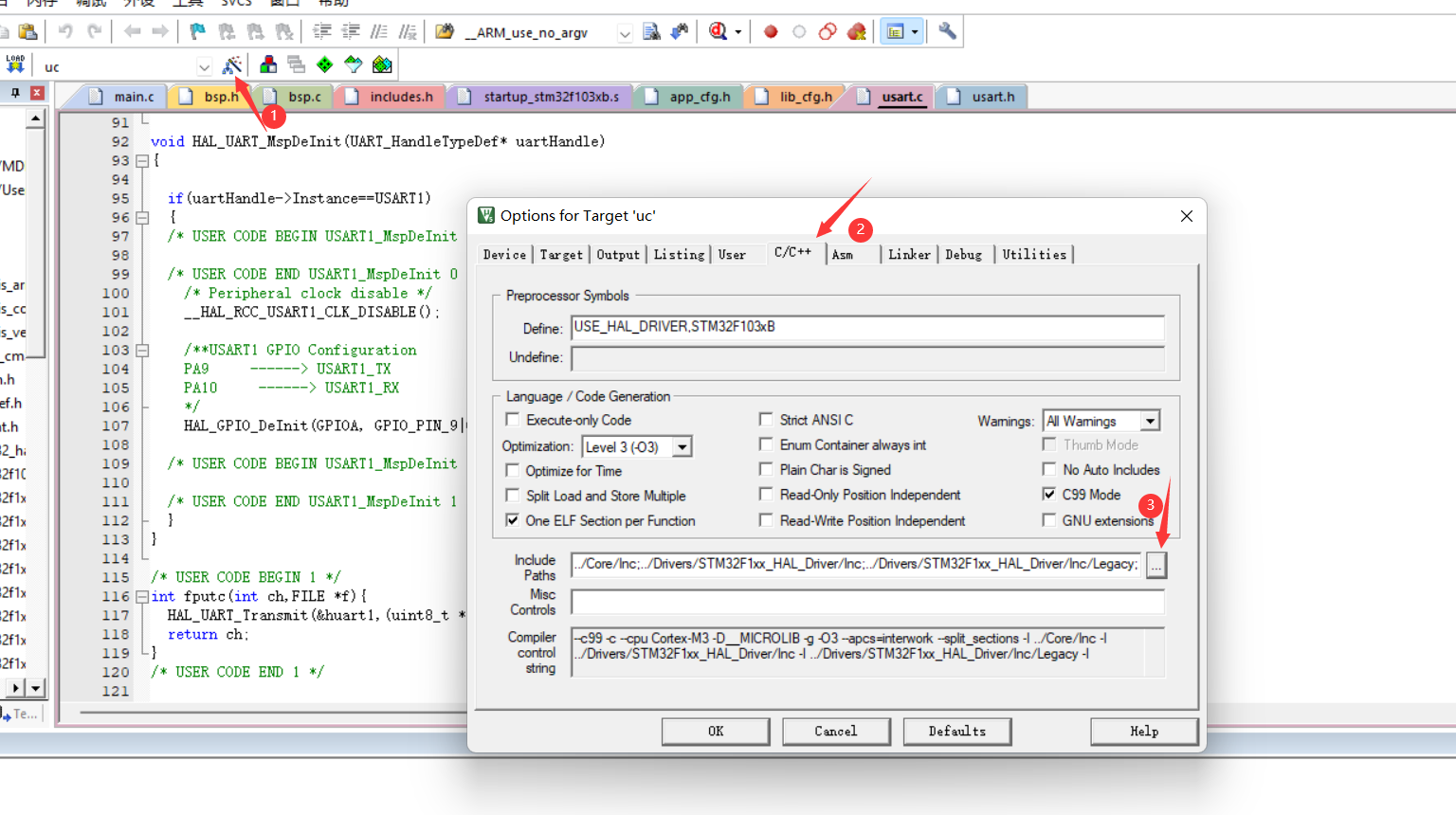
This step is to add the path corresponding to the file just added, otherwise an error will be reported during compilation and the corresponding file cannot be found. The result after adding is shown in the figure. If we follow the above step by step, eight paths should be added correctly.
3. Modify the contents of the document
① bsp.c and bsp.h
bsp:
Add the following code to the bsp.c file:
// bsp.c
#include "includes.h"

#define  DWT_CR      *(CPU_REG32 *)0xE0001000
#define  DWT_CYCCNT  *(CPU_REG32 *)0xE0001004
#define  DEM_CR      *(CPU_REG32 *)0xE000EDFC
#define  DBGMCU_CR   *(CPU_REG32 *)0xE0042004

#define  DEM_CR_TRCENA                   (1 << 24)
#define  DWT_CR_CYCCNTENA                (1 <<  0)

CPU_INT32U  BSP_CPU_ClkFreq (void)
{
    return HAL_RCC_GetHCLKFreq();
}

void BSP_Tick_Init(void)
{
	CPU_INT32U cpu_clk_freq;
	CPU_INT32U cnts;
	cpu_clk_freq = BSP_CPU_ClkFreq();

	#if(OS_VERSION>=3000u)
		cnts = cpu_clk_freq/(CPU_INT32U)OSCfg_TickRate_Hz;
	#else
		cnts = cpu_clk_freq/(CPU_INT32U)OS_TICKS_PER_SEC;
	#endif
	OS_CPU_SysTickInit(cnts);
}


void BSP_Init(void)
{
	BSP_Tick_Init();
	MX_GPIO_Init();
}


#if (CPU_CFG_TS_TMR_EN == DEF_ENABLED)
void  CPU_TS_TmrInit (void)
{
    CPU_INT32U  cpu_clk_freq_hz;


    DEM_CR         |= (CPU_INT32U)DEM_CR_TRCENA;                /* Enable Cortex-M3's DWT CYCCNT reg.                   */
    DWT_CYCCNT      = (CPU_INT32U)0u;
    DWT_CR         |= (CPU_INT32U)DWT_CR_CYCCNTENA;

    cpu_clk_freq_hz = BSP_CPU_ClkFreq();
    CPU_TS_TmrFreqSet(cpu_clk_freq_hz);
}
#endif


#if (CPU_CFG_TS_TMR_EN == DEF_ENABLED)
CPU_TS_TMR  CPU_TS_TmrRd (void)
{
    return ((CPU_TS_TMR)DWT_CYCCNT);
}
#endif


#if (CPU_CFG_TS_32_EN == DEF_ENABLED)
CPU_INT64U  CPU_TS32_to_uSec (CPU_TS32  ts_cnts)
{
	CPU_INT64U  ts_us;
  CPU_INT64U  fclk_freq;


  fclk_freq = BSP_CPU_ClkFreq();
  ts_us     = ts_cnts / (fclk_freq / DEF_TIME_NBR_uS_PER_SEC);

  return (ts_us);
}
#endif


#if (CPU_CFG_TS_64_EN == DEF_ENABLED)
CPU_INT64U  CPU_TS64_to_uSec (CPU_TS64  ts_cnts)
{
	CPU_INT64U  ts_us;
	CPU_INT64U  fclk_freq;


  fclk_freq = BSP_CPU_ClkFreq();
  ts_us     = ts_cnts / (fclk_freq / DEF_TIME_NBR_uS_PER_SEC);

  return (ts_us);
}
#endif
bsp.h:
Add the following code to bsp.h:
// bsp.h
#ifndef  __BSP_H__
#define  __BSP_H__

#include "stm32f1xx_hal.h"

void BSP_Init(void);

#endif
②main.c
Replace the code in the whole main.c file with the following code:
/* USER CODE END Header */
/* Includes ------------------------------------------------------------------*/
#include "main.h"
#include "gpio.h"
#include "usart.h"
/* Private includes ----------------------------------------------------------*/
/* USER CODE BEGIN Includes */
#include <includes.h>
#include "cpu.h"
#include "stm32f1xx_hal.h"
/* USER CODE END Includes */

/* Private typedef -----------------------------------------------------------*/
/* USER CODE BEGIN PTD */

/* USER CODE END PTD */

/* Private define ------------------------------------------------------------*/
/* USER CODE BEGIN PD */
/* Task priority */
#define START_TASK_PRIO		3
#define LED0_TASK_PRIO		4
#define MSG_TASK_PRIO		5
#define LED1_TASK_PRIO		6

/* Task stack size	*/
#define START_STK_SIZE 		96
#define LED0_STK_SIZE 		64
#define MSG_STK_SIZE 		64
#define LED1_STK_SIZE 		64

/* Task stack */
CPU_STK START_TASK_STK[START_STK_SIZE];
CPU_STK LED0_TASK_STK[LED0_STK_SIZE];
CPU_STK MSG_TASK_STK[MSG_STK_SIZE];
CPU_STK LED1_TASK_STK[LED1_STK_SIZE];

/* Task control block */
OS_TCB StartTaskTCB;
OS_TCB Led0TaskTCB;
OS_TCB MsgTaskTCB;
OS_TCB Led1TaskTCB;

/* USER CODE END PD */

/* Private macro -------------------------------------------------------------*/
/* USER CODE BEGIN PM */

/* USER CODE END PM */

/* Private variables ---------------------------------------------------------*/

/* USER CODE BEGIN PV */

/* Task function definition */
void start_task(void *p_arg);
static  void  AppTaskCreate(void);
static  void  AppObjCreate(void);
static  void  led_pc13(void *p_arg);
static  void  send_msg(void *p_arg);
static  void  led_pa3(void *p_arg);
/* USER CODE END PV */

/* Private function prototypes -----------------------------------------------*/
void SystemClock_Config(void);
/* USER CODE BEGIN PFP */

/* USER CODE END PFP */

/* Private user code ---------------------------------------------------------*/
/* USER CODE BEGIN 0 */
/**
  * @brief System Clock Configuration
  * @retval None
  */
void SystemClock_Config(void)
{
  RCC_OscInitTypeDef RCC_OscInitStruct = {0};
  RCC_ClkInitTypeDef RCC_ClkInitStruct = {0};

  /**Initializes the CPU, AHB and APB busses clocks
  */
  RCC_OscInitStruct.OscillatorType = RCC_OSCILLATORTYPE_HSE;
  RCC_OscInitStruct.HSEState = RCC_HSE_ON;
  RCC_OscInitStruct.HSEPredivValue = RCC_HSE_PREDIV_DIV1;
  RCC_OscInitStruct.HSIState = RCC_HSI_ON;
  RCC_OscInitStruct.PLL.PLLState = RCC_PLL_ON;
  RCC_OscInitStruct.PLL.PLLSource = RCC_PLLSOURCE_HSE;
  RCC_OscInitStruct.PLL.PLLMUL = RCC_PLL_MUL9;
  if (HAL_RCC_OscConfig(&RCC_OscInitStruct) != HAL_OK)
  {
    Error_Handler();
  }
  /**Initializes the CPU, AHB and APB busses clocks
  */
  RCC_ClkInitStruct.ClockType = RCC_CLOCKTYPE_HCLK|RCC_CLOCKTYPE_SYSCLK
                              |RCC_CLOCKTYPE_PCLK1|RCC_CLOCKTYPE_PCLK2;
  RCC_ClkInitStruct.SYSCLKSource = RCC_SYSCLKSOURCE_PLLCLK;
  RCC_ClkInitStruct.AHBCLKDivider = RCC_SYSCLK_DIV1;
  RCC_ClkInitStruct.APB1CLKDivider = RCC_HCLK_DIV2;
  RCC_ClkInitStruct.APB2CLKDivider = RCC_HCLK_DIV1;

  if (HAL_RCC_ClockConfig(&RCC_ClkInitStruct, FLASH_LATENCY_2) != HAL_OK)
  {
    Error_Handler();
  }
}

/* USER CODE END 0 */

/**
  * @brief  The application entry point.
  * @retval int
  */
int main(void)
{
	OS_ERR  err;
	OSInit(&err);
  HAL_Init();
	SystemClock_Config();
	//MX_GPIO_Init();  This will also be initialized in BSP initialization
  MX_USART1_UART_Init();
	/* Create task */
	OSTaskCreate((OS_TCB     *)&StartTaskTCB,                /* Create the start task                                */
				 (CPU_CHAR   *)"start task",
				 (OS_TASK_PTR ) start_task,
				 (void       *) 0,
				 (OS_PRIO     ) START_TASK_PRIO,
				 (CPU_STK    *)&START_TASK_STK[0],
				 (CPU_STK_SIZE) START_STK_SIZE/10,
				 (CPU_STK_SIZE) START_STK_SIZE,
				 (OS_MSG_QTY  ) 0,
				 (OS_TICK     ) 0,
				 (void       *) 0,
				 (OS_OPT      )(OS_OPT_TASK_STK_CHK | OS_OPT_TASK_STK_CLR),
				 (OS_ERR     *)&err);
	/* Start the multitasking system and give control to uC/OS-III */
	OSStart(&err);            /* Start multitasking (i.e. give control to uC/OS-III). */

}


void start_task(void *p_arg)
{
	OS_ERR err;
	CPU_SR_ALLOC();
	p_arg = p_arg;

	/* YangJie add 2021.05.20*/
  BSP_Init();                                                   /* Initialize BSP functions */
  //CPU_Init();
  //Mem_Init();                                                 /* Initialize Memory Management Module */

#if OS_CFG_STAT_TASK_EN > 0u
   OSStatTaskCPUUsageInit(&err);  		//Statistical tasks
#endif

#ifdef CPU_CFG_INT_DIS_MEAS_EN 			// If enabled, measure the interrupt off time
    CPU_IntDisMeasMaxCurReset();
#endif

#if 	 OS_CFG_SCHED_ROUND_ROBIN_EN   		// When using time slice rotation
	 //Enable the time slice rotation scheduling function. The time slice length is 1 system clock beat, i.e. 1*5=5ms
	OSSchedRoundRobinCfg(DEF_ENABLED,1,&err);
#endif

	OS_CRITICAL_ENTER();	//Enter critical zone
	/* Create LED0 task */
	OSTaskCreate((OS_TCB 	* )&Led0TaskTCB,
				 (CPU_CHAR	* )"led_pc13",
                 (OS_TASK_PTR )led_pc13,
                 (void		* )0,
                 (OS_PRIO	  )LED0_TASK_PRIO,
                 (CPU_STK   * )&LED0_TASK_STK[0],
                 (CPU_STK_SIZE)LED0_STK_SIZE/10,
                 (CPU_STK_SIZE)LED0_STK_SIZE,
                 (OS_MSG_QTY  )0,
                 (OS_TICK	  )0,
                 (void   	* )0,
                 (OS_OPT      )OS_OPT_TASK_STK_CHK|OS_OPT_TASK_STK_CLR,
                 (OS_ERR 	* )&err);

/* Create LED1 task */
	OSTaskCreate((OS_TCB 	* )&Led1TaskTCB,
				 (CPU_CHAR	* )"led_pa3",
                 (OS_TASK_PTR )led_pa3,
                 (void		* )0,
                 (OS_PRIO	  )LED1_TASK_PRIO,
                 (CPU_STK   * )&LED1_TASK_STK[0],
                 (CPU_STK_SIZE)LED1_STK_SIZE/10,
                 (CPU_STK_SIZE)LED1_STK_SIZE,
                 (OS_MSG_QTY  )0,
                 (OS_TICK	  )0,
                 (void   	* )0,
                 (OS_OPT      )OS_OPT_TASK_STK_CHK|OS_OPT_TASK_STK_CLR,
                 (OS_ERR 	* )&err);

	/* Create MSG task */
	OSTaskCreate((OS_TCB 	* )&MsgTaskTCB,
				 (CPU_CHAR	* )"send_msg",
                 (OS_TASK_PTR )send_msg,
                 (void		* )0,
                 (OS_PRIO	  )MSG_TASK_PRIO,
                 (CPU_STK   * )&MSG_TASK_STK[0],
                 (CPU_STK_SIZE)MSG_STK_SIZE/10,
                 (CPU_STK_SIZE)MSG_STK_SIZE,
                 (OS_MSG_QTY  )0,
                 (OS_TICK	  )0,
                 (void   	* )0,
                 (OS_OPT      )OS_OPT_TASK_STK_CHK|OS_OPT_TASK_STK_CLR,
                 (OS_ERR 	* )&err);

	OS_TaskSuspend((OS_TCB*)&StartTaskTCB,&err);		//Suspend start task
	OS_CRITICAL_EXIT();	//Enter critical zone
}
/**
  * Function function: start the task function body.
  * Input parameter: p_arg is the formal parameter passed when the task was created
  * Return value: None
  * Description: None
  */
static  void  led_pc13 (void *p_arg)
{
  OS_ERR      err;

  (void)p_arg;

  BSP_Init();                                                 /* Initialize BSP functions                             */
  CPU_Init();

  Mem_Init();                                                 /* Initialize Memory Management Module                  */

#if OS_CFG_STAT_TASK_EN > 0u
  OSStatTaskCPUUsageInit(&err);                               /* Compute CPU capacity with no task running            */
#endif

  CPU_IntDisMeasMaxCurReset();

  AppTaskCreate();                                            /* Create Application Tasks                             */

  AppObjCreate();                                             /* Create Application Objects                           */

  while (DEF_TRUE)
  {
		HAL_GPIO_WritePin(GPIOC,GPIO_PIN_13,GPIO_PIN_RESET);
		OSTimeDlyHMSM(0, 0, 1, 0,OS_OPT_TIME_HMSM_STRICT,&err);
		HAL_GPIO_WritePin(GPIOC,GPIO_PIN_13,GPIO_PIN_SET);
		OSTimeDlyHMSM(0, 0, 1, 0,OS_OPT_TIME_HMSM_STRICT,&err);
    /* USER CODE END WHILE */

    /* USER CODE BEGIN 3 */
  }
  /* USER CODE END 3 */
}

static  void  led_pa3 (void *p_arg)
{
  OS_ERR      err;

  (void)p_arg;

  BSP_Init();                                                 /* Initialize BSP functions                             */
  CPU_Init();

  Mem_Init();                                                 /* Initialize Memory Management Module                  */

#if OS_CFG_STAT_TASK_EN > 0u
  OSStatTaskCPUUsageInit(&err);                               /* Compute CPU capacity with no task running            */
#endif

  CPU_IntDisMeasMaxCurReset();

  AppTaskCreate();                                            /* Create Application Tasks                             */

  AppObjCreate();                                             /* Create Application Objects                           */

  while (DEF_TRUE)
  {
		HAL_GPIO_WritePin(GPIOA,GPIO_PIN_3,GPIO_PIN_RESET);
		OSTimeDlyHMSM(0, 0, 3, 0,OS_OPT_TIME_HMSM_STRICT,&err);
		HAL_GPIO_WritePin(GPIOA,GPIO_PIN_3,GPIO_PIN_SET);
		OSTimeDlyHMSM(0, 0, 3, 0,OS_OPT_TIME_HMSM_STRICT,&err);
    /* USER CODE END WHILE */

    /* USER CODE BEGIN 3 */
  }
  /* USER CODE END 3 */
}

static  void  send_msg (void *p_arg)
{
  OS_ERR      err;

  (void)p_arg;

  BSP_Init();                                                 /* Initialize BSP functions                             */
  CPU_Init();

  Mem_Init();                                                 /* Initialize Memory Management Module                  */

#if OS_CFG_STAT_TASK_EN > 0u
  OSStatTaskCPUUsageInit(&err);                               /* Compute CPU capacity with no task running            */
#endif

  CPU_IntDisMeasMaxCurReset();

  AppTaskCreate();                                            /* Create Application Tasks                             */

  AppObjCreate();                                             /* Create Application Objects                           */

  while (DEF_TRUE)
  {
			printf("hello uc/OS \r\n");
		OSTimeDlyHMSM(0, 0, 2, 0,OS_OPT_TIME_HMSM_STRICT,&err);
    /* USER CODE END WHILE */

    /* USER CODE BEGIN 3 */
  }
  /* USER CODE END 3 */
}


/* USER CODE BEGIN 4 */
/**
  * Function function: create application task
  * Input parameter: p_arg is the formal parameter passed when the task was created
  * Return value: None
  * Description: None
  */
static  void  AppTaskCreate (void)
{

}


/**
  * Function function: uCOSIII kernel object creation
  * Input parameters: None
  * Return value: None
  * Description: None
  */
static  void  AppObjCreate (void)
{

}

/* USER CODE END 4 */

/**
  * @brief  This function is executed in case of error occurrence.
  * @retval None
  */
void Error_Handler(void)
{
  /* USER CODE BEGIN Error_Handler_Debug */
  /* User can add his own implementation to report the HAL error return state */

  /* USER CODE END Error_Handler_Debug */
}

#ifdef  USE_FULL_ASSERT
/**
  * @brief  Reports the name of the source file and the source line number
  *         where the assert_param error has occurred.
  * @param  file: pointer to the source file name
  * @param  line: assert_param error line source number
  * @retval None
  */
void assert_failed(uint8_t *file, uint32_t line)
{
  /* USER CODE BEGIN 6 */
  /* User can add his own implementation to report the file name and line number,
     tex: printf("Wrong parameters value: file %s on line %d\r\n", file, line) */
  /* USER CODE END 6 */
}
#endif /* USE_FULL_ASSERT */

/************************ (C) COPYRIGHT STMicroelectronics *****END OF FILE****/
③ Startup file
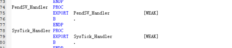
Find the startup file and open it. Find the following two lines of code at lines 75 and 76:
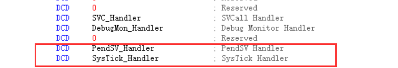
Add PendSV_Handler and systick_ Change handler to OS_CPU_PendSVHandler and OS_CPU_SysTickHandler
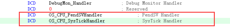
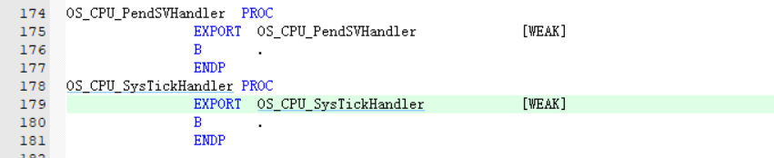
Then, find the 170th line and modify the two codes, paying attention to the modification before and after, and do not omit:
After modification, as shown in the figure:
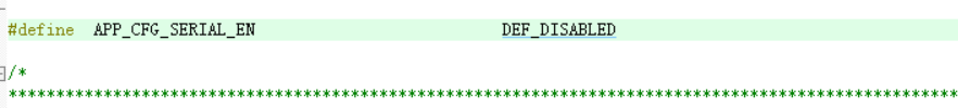
④app_cfg.h
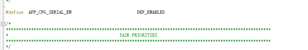
On OS_ Find app under CFG group_ CFG. H file, on line 42
#define APP_CFG_SERIAL_EN DEF_ENABLED
Amend to read:
#define APP_CFG_SERIAL_EN DEF_DISABLED
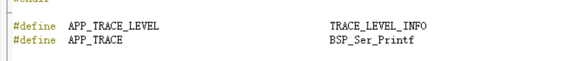
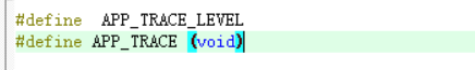
Find line 85 and place
#define APP_TRACE BSP_Ser_Printf
Amend to read:
#define APP_TRACE (void)
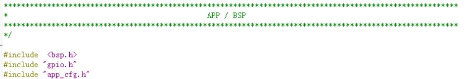
⑤ includes.h
On OS_ Find includes.h under CFG group
Add two lines of code under line 68:
#include "gpio.h"
#include "app_cfg.h"
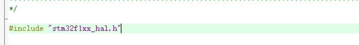
Then modify the library at the 80th line below
take
#include <stm32f10x_lib.h>
Change to
#include "stm32f1xx_hal.h"

After modification:
⑥ lib_cfg.h
On OS_ Find lib under CFG group_ cfg.h
Change it to 5 here (the macro definition here sets the size of heap space. The RAM of STM32F103C8T6 is only 20K, so it should be reduced a little):
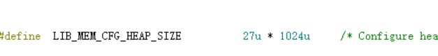
After modification:

⑦ usart.c and usart.h
Since we use the printf function, we need to add the following code to the usart.c file to complete the printf redirection:
usart.c:
/* USER CODE BEGIN 1 */
int fputc(int ch,FILE *f){
	HAL_UART_Transmit(&huart1,(uint8_t *)&ch,1,0xffff);
	return ch;
}
/* USER CODE END 1 */
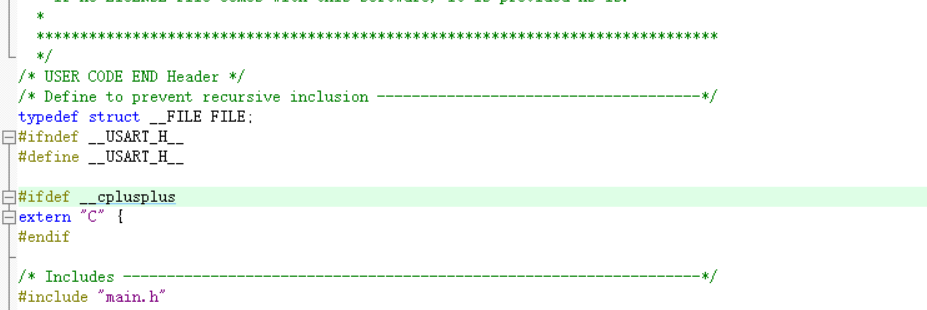
Then we need to define our variable FILE in usart.h FILE, so add the following code in front of the header FILE:
typedef struct __FILE FILE;
4. Modify parameters
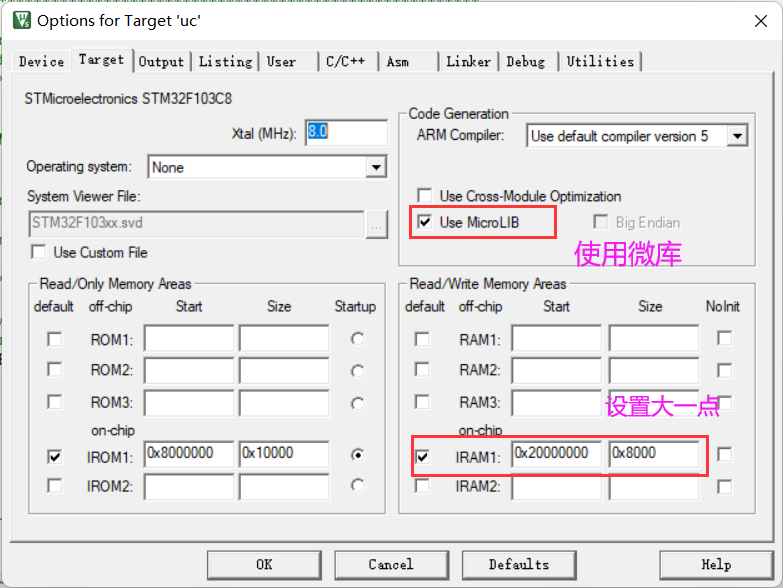
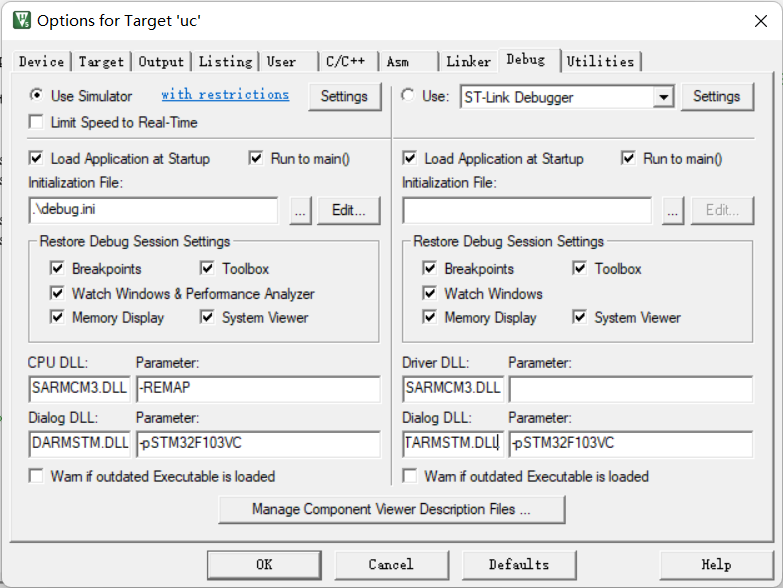
If simulation is used, the following modifications shall be made:
First, click the magic wand, click the debug option, and select Use Simulator to use simulation.
Modify the following Diolag DLL to DARMSTM.DLL
Modify the following Parameter to - pSTM32F103VC
Modify the Diolag DLL on the right to TARMSTM.DLL
Modify the Parameter on the right to - pSTM32F103VC
Click OK to complete the setup
Create a new debug.ini file under the us project path and write it in the file
map 0x40000000, 0x40007FFF read write // APB1
map 0x40010000, 0x400157FF read write // APB2
map 0x40020000, 0x4007FFFF read write // AHB1
map 0x50000000, 0x50060BFF read write // AHB2
map 0x60000000, 0x60000FFF read write // AHB3
map 0xE0000000, 0xE00FFFFF read write // CORTEX-M4 internal peripherals
Add this file to the Initialization File
The migration is now complete.
4, Code explanation and compilation test
1. Subject requirements
1. Learn embedded real-time operating system (RTOS), take uc/OS-III as an example, transplant it to stm32F103, and build at least three task s:
Two task s control the LED on-off in 1s and 3s cycles respectively;
Another task sends "hello uc/OS! Welcome to RTOS multitasking environment!" through the serial port in a 2s cycle.
Record the detailed migration process.
2. In the above experiments, in addition to mastering Keil's simulation and debugging code function, we also learned to use instruments to troubleshoot and test the code operation.
- Practice using an oscilloscope to observe the LED output level and the waveform of serial communication, and analyze the fault;
- Keil virtual simulation logic instrument and real logic instrument (SaleaeLogic16) are used to capture the LED output level and the waveform of serial communication for protocol analysis.
2. Code introduction
According to the requirements of the topic, we need to turn on and off the LED light in 1s and 3s cycles.
According to our previous experiments, we need to initialize the GPIO pin we want to use first, but because we are a project generated with CubeMX, after setting the corresponding pin in CubeMX, we have automatically initialized the pin in gpio.c.
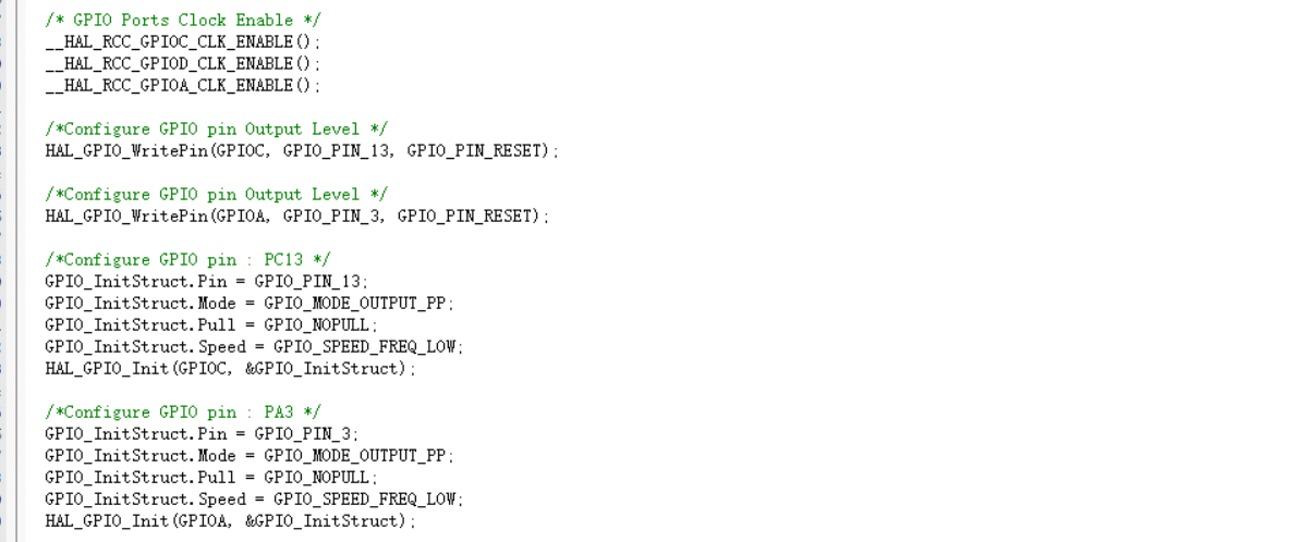
Similarly, there are serial port initialization and so on, which have been automatically configured.
We just need to rewrite the main.c file. The main task is to create a multi task system and give control to the uC/OS-III operating system. We need to create tasks first according to the needs of tasks. Because we require three tasks, here we create three tasks and name them respectively.
Then is the function body for starting the task. For the three tasks, set the time to 1s, 3s and 2s respectively.
3. Operation results
As shown in the figure, the green light is PC13 pin. It can be seen that when the flashing frequency is 1s, it is on for 1s and off for 1s.
The yellow light is PA3, on for 3s and off for 3s.
It meets the experimental requirements and the experiment is successful.
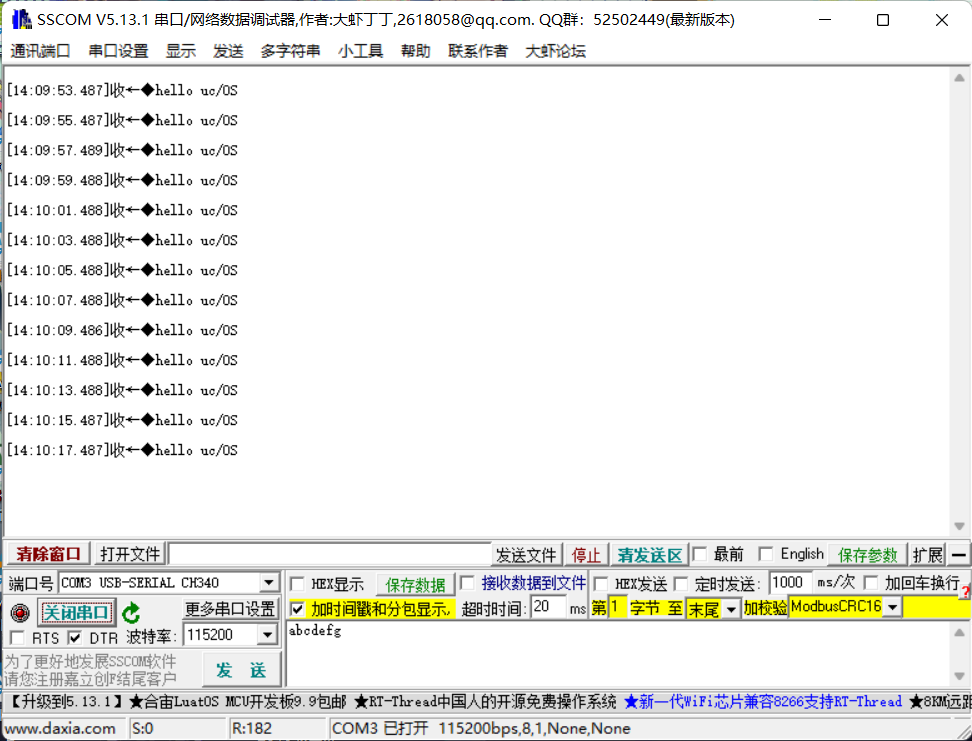
As shown in the figure, the serial port information can be seen. After opening the serial port, the information is sent every 2s, and the corresponding experiment is completed.
5, Logic analyzer
1. Simulation logic analyzer
For the use of simulation logic analyzer, please refer to my previous article: https://blog.csdn.net/cleveryoga/article/details/120999566
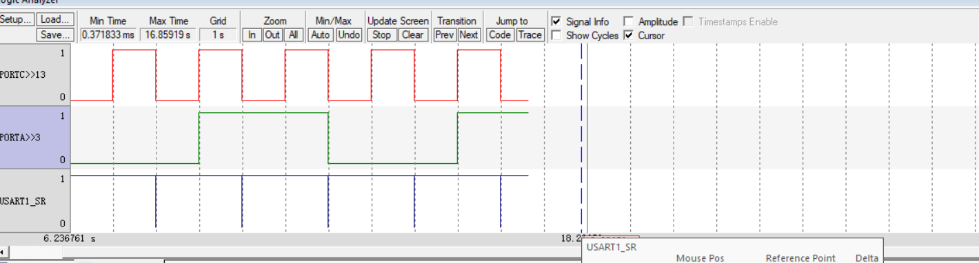
Here, directly observe the waveform as shown in the figure. PORTC13 is a waveform with a flashing period of 1s. If the Grid above is 1s, it means that the length of a square is 1s. Observe the red channel and see that it is true. 1s low level is off, and 1s high level is on.
Observe the No. 2 PORTA3 channel. Because the flashing period we set earlier is 3s, it corresponds to three grids, that is, 3s. We can visually see the 1:3 relationship corresponding to the above red channel.
Observe the serial port of channel 3. After the vertical line is enlarged, the transmitted information is transmitted. The period is 2 grids, that is, 2s, which is also in line with the period of 2s of the code written above.
2. Real logic analyzer

First of all, let's briefly introduce the use of logic analyzer here. It is somewhat similar to the use of oscilloscope. We need to observe the signal of which pin and connect which signal to the corresponding channel of oscilloscope, because we use three pins to observe two lighting and one serial port respectively. Here, three channels are connected. As shown in the figure, channel 0 is 1s lighting, Channel 1 is a serial port, and channel 2 is 3s lighting.
First, observe channel 0. When I place the mouse at the high level, I can see that as shown in the figure, a high level cycle is 1s, the frequency is 0.5Hz, and the cycle for the whole waveform is 2s, which is the same as that observed by our simulation logic analyzer.
Then observe the 3s lighting of channel 2 and see that its cycle is three times that of channel 0, which corresponds to the same results of our code and simulation logic analyzer.
The observation period of the serial port of channel 1 is 2s, which is in line with the experimental content.
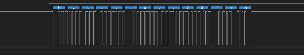
We enlarge the vertical line of channel 1, which represents the data sent by our serial port. As shown in the figure, we can see that we sent hello"uc/os" \r\n, which is preceded by the data we sent, followed by \ r carriage return and \ N line feed.
It can also be observed that the transmission time of an h character is about 80 microseconds, and there is the same delay interval between each character.
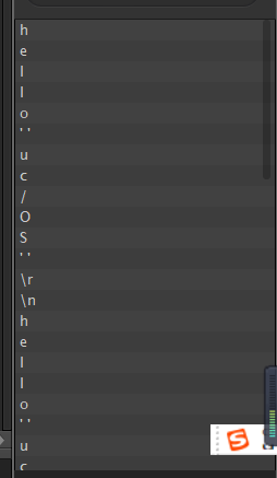
In the lower right corner of the logic analyzer, you can also see the content we transmit, which corresponds to the same.
6, Summary
This experiment mainly carries out the transplantation of uCOS, from the preparation of files before transplantation to the addition of files during transplantation. The whole process requires us to be very careful, otherwise there will be many errors such as missing files or undefined variables during compilation.
7, References
https://blog.csdn.net/qq_21805743/article/details/120780866
https://blog.csdn.net/weixin_43116606/article/details/105532222