I. Preparations
1. What is a STM32 chip?
STM32, literally, ST is an Italian Semiconductor, M is the abbreviation of Microelectronics, 32 stands for 32 bits. Together, STM32 is a 32-bit microcontroller developed by ST Company. In today's 32-bit controller, STM32 can be said to be the brightest star, it is spoiled, favored by engineers and the market, no core can come out of its right.
STM32 is a microcontroller with many common communication interfaces, such as USART, I2C, SPI, etc. It can connect many sensors and control many devices. In real life, many electrical products we come into contact with have the image of STM32, such as smart hand rings, micro quad-axis vehicle, balance car, mobile POST machine, smart rice cooker, 3D printer and so on.
STM32 has many series to meet the various needs of the market, including Cortex-M0, M3, M4 and M7 from the core, each of which is roughly divided into mainstream, high performance and low power consumption.
From a learning point of view, F1 and F4 can be selected. F1 represents the basic type. Based on Core-M3, the main frequency is 72MHZ, F4 represents high performance, based on Core-M4, the main frequency is 180M. This article selects stm32f103c8t6 under F1.
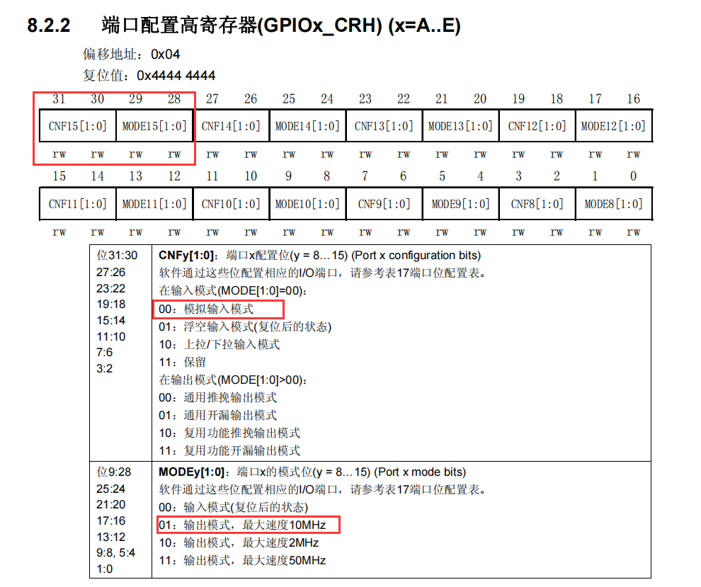
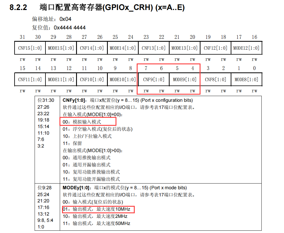
2. GPIO-related registers
The first thing you need to know is that the operation of the GPIO port in STM32 is nothing more than the registers under the operation. The so-called standard libraries or HAL libraries are just encapsulating the operation of the registers in order to reduce the workload of your programming. So for the description of registers, you just need to know a little bit about what each register does, what bits it has, and how it is configured. There's no need to remember everything except what you think you need to be aware of. Just know where to look when you use it.
Two 32-bit configuration registers: GPIOx_CRL, GPIOx_CRH
Two 32-bit data registers: GPIOx_IDR, GPIOx_ODR
A 32-bit bit bit bit/reset register: GPIOx_BSRR
A 16-bit reset register: GPIOx_BRR
A 32-bit lock register: GPIOx_LCKR
Note: The specific register description can be referred to page P113 of the GPIO chapter of STM32F10x - Chinese Reference Manual. It is strongly recommended that you take a few minutes to review this section first.
-
GPIO Address
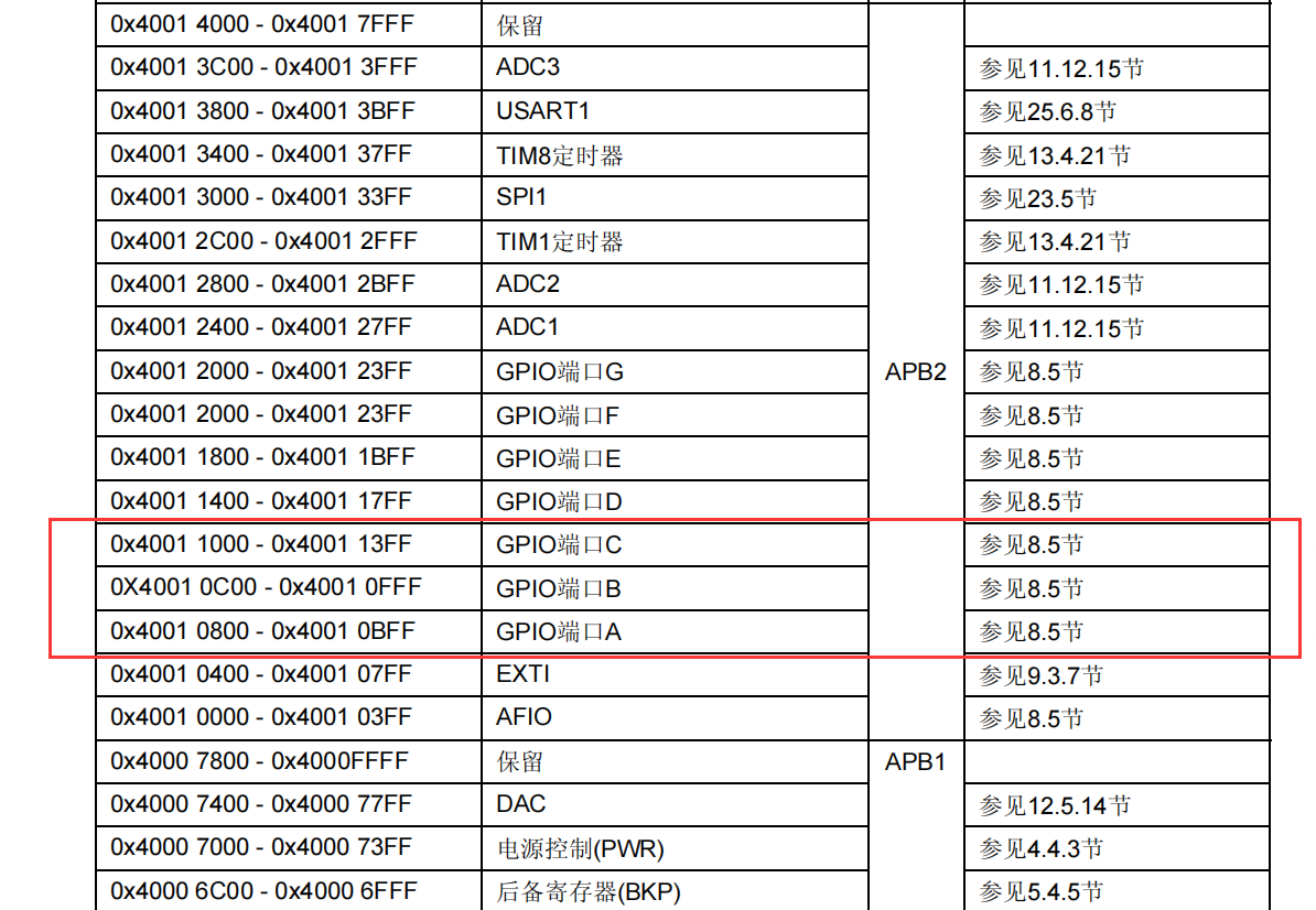
-
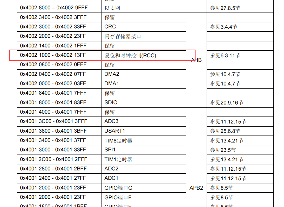
Clock Address
-
Initialization address and GPIO offset
2. Operation of GPIO output
- A0
- C15
- B9
GPIO port has eight modes:
1. Input Floating
2. Input Pull Up
3. Input Dropdown
4. Analog input
5. Leak-out output
6. Push-pull output
7. Push-pull multiplexing function
8. Open-Leak Multiplexing Function
Light up the LED here using push-pull output.
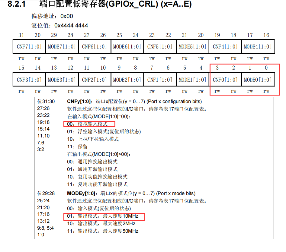
Ports 1-7 are low and ports 8-15 are high. Each pin is controlled by four bits.
1. Initialize GPIO
Take GPIO A pin 0 (A0) as an example, set it to push-pull output, and set the maximum speed to 10MHz, then set the four bits that control A0 to 0001. Similarly, you can get two other settings from the figure above.
For A0 of GPIOA, C15 of GPIOC, B9 of GPIOB, the initialization settings are as follows:
#define GPIOB_CRH (*(unsigned int *)0x40010C04)
#define GPIOC_CRH (*(unsigned int *)0x40011004)
#define GPIOA_CRL (*(unsigned int *)0x40010800)

// Configure GPIO port for push-exempt output
// GPIOB - last four digits 0001
GPIOB_CRH |= (1<<4);  // Last Bit Change 1
GPIOB_CRH &= ~(0xE<<0);  // The last 2, 3, 4 bits change to 0
// GPIOC - top four digits 0001
GPIOC_CRH |= (1<<28);  //  Fourth Bit Variant 1
GPIOC_CRH &= ~(0xE0000000);  // Top Three Varies 0
// GPIOA - last four digits 0001
GPIOA_CRL |= (1<<0);  // Last Bit Change 1
GPIOA_CRL &= ~(0xE<<0);  // The last 2, 3, 4 bits change to 0
2. Set low level
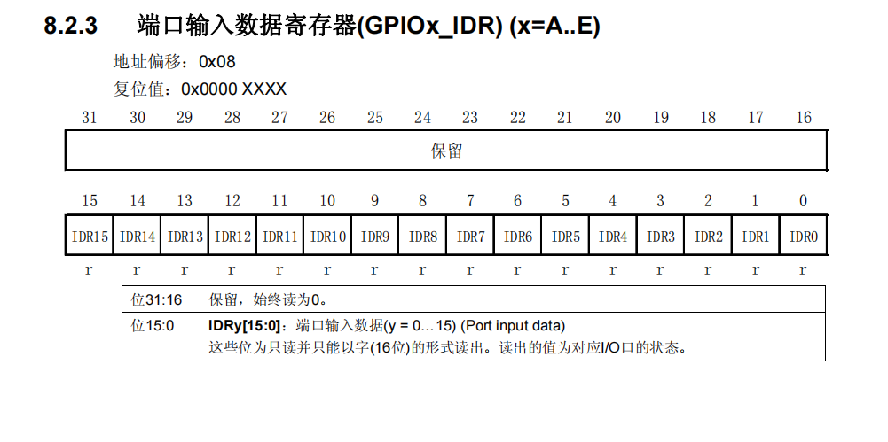
Output high level is 1, low level is 0.
For B9 of GPIOB, C15 of GPIOC, A0 of GPIOA, the settings are as follows:
#define GPIOB_ODR (*(unsigned int *)0x40010C0C)
#define GPIOC_ODR (*(unsigned int *)0x4001100C)
#define GPIOA_ODR (*(unsigned int *)0x4001080C)

GPIOB_ODR &= ~(1<<9);  //The last bit becomes zero
GPIOC_ODR &= ~(1<<15); //The last 16 bits become zero
GPIOA_ODR &= ~(1<<0);  //The last bit becomes
3. Creating Projects
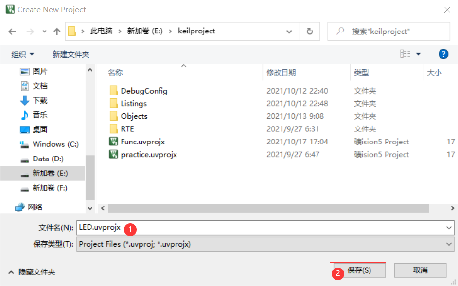
1. New Project
Click New uVision Project under Project and enter the file name LED:
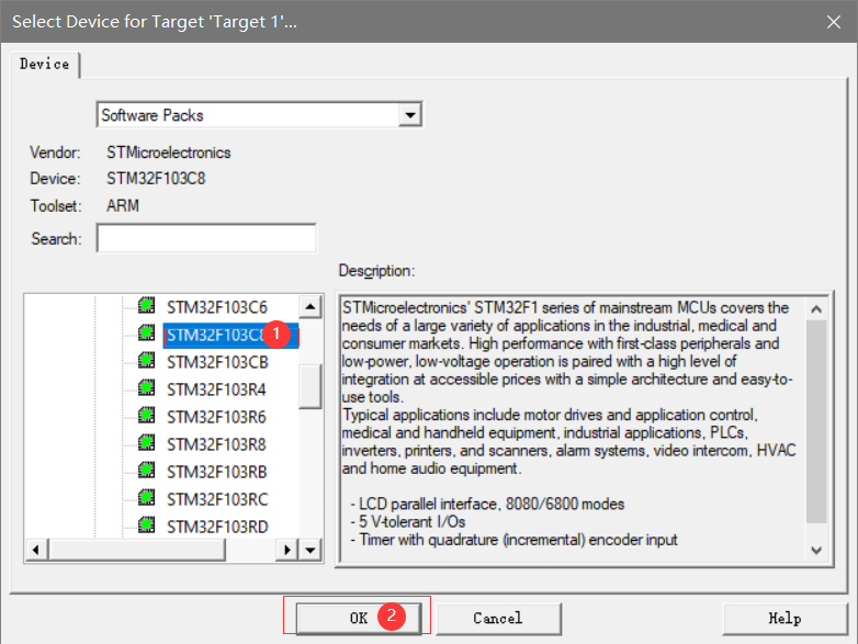
Select the chip (here I'm using STM32F103C8T6):
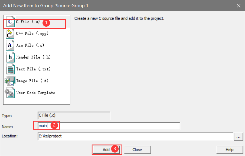
Add file main.c:
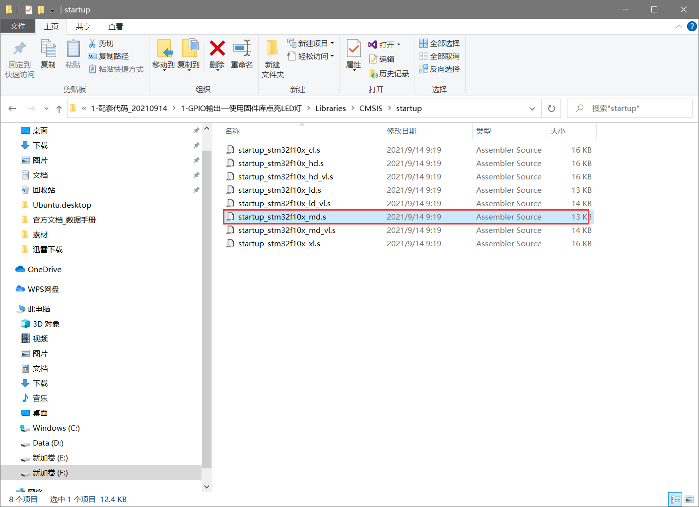
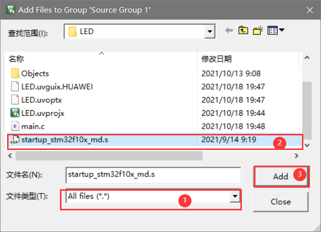
Paste the startup file from the downloaded code package into the project directory:
(Download address: Wildfire Data Download Center)
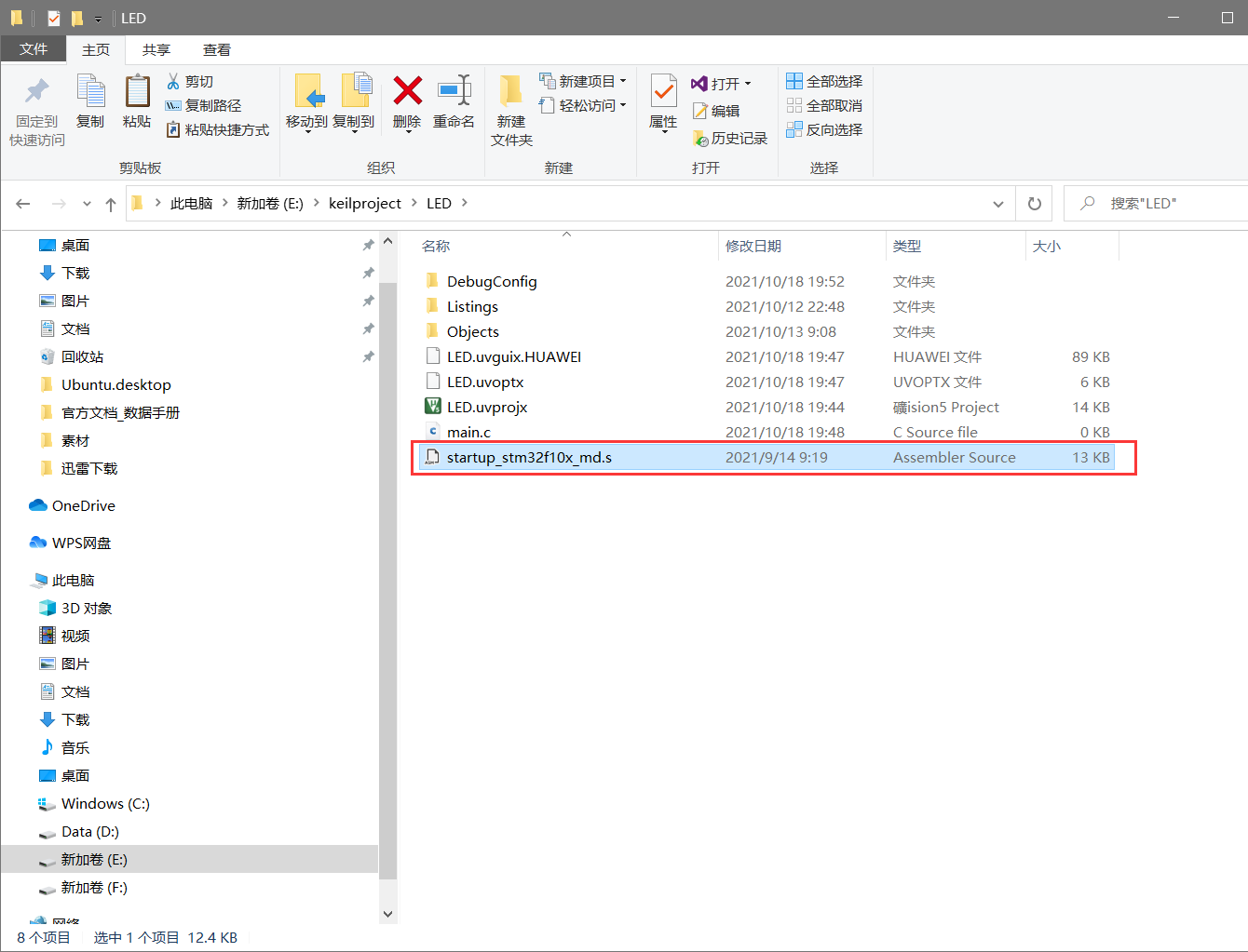
Import the startup file:
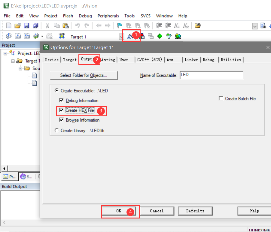
Click on the Magic Wand settings to generate the HEX file (required for later burning!):
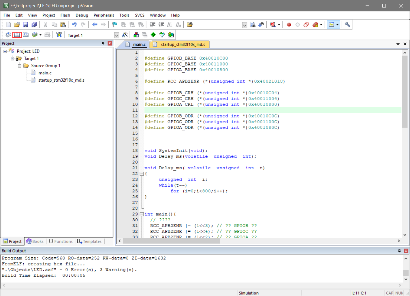
2. Write Code
Code:
#define GPIOB_BASE 0x40010C00
#define GPIOC_BASE 0x40011000
#define GPIOA_BASE 0x40010800
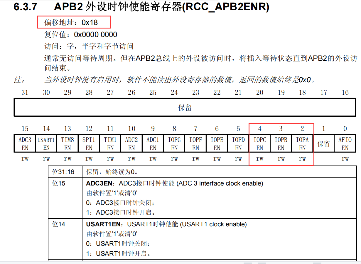
#define RCC_APB2ENR (*(unsigned int *)0x40021018)
#define GPIOB_CRH (*(unsigned int *)0x40010C04)
#define GPIOC_CRH (*(unsigned int *)0x40011004)
#define GPIOA_CRL (*(unsigned int *)0x40010800)
#define GPIOB_ODR (*(unsigned int *)0x40010C0C)
#define GPIOC_ODR (*(unsigned int *)0x4001100C)
#define GPIOA_ODR (*(unsigned int *)0x4001080C)
void SystemInit(void);
void Delay_ms(volatile unsigned int);
void Delay_ms( volatile unsigned int t)
{
unsigned int i;
while(t--)
for (i=0;i<800;i++);
}
int main(){
// ????
RCC_APB2ENR |= (1<<3); // ?? GPIOB ??
RCC_APB2ENR |= (1<<4); // ?? GPIOC ??
RCC_APB2ENR |= (1<<2); // ?? GPIOA ??
// ?? GPIO ?????
// ?? GPIOB ???? 0001 (B9)
GPIOB_CRH|=(1<<4); //???????
GPIOB_CRH&= ~(0xE0000000); //??? ??
// ?? GPIOC ???? 0001 (C15)
GPIOC_CRH |= (1<<28); // ??????1
GPIOC_CRH &= ~(0xE0000000); // ??????0
// ?? GPIOA ????? 0001 (A0)
GPIOA_CRL |= (1<<0); // ???????1
GPIOA_CRL &= ~(0xE0000000); // ???????????0
// 3?LED??????(????)
GPIOB_ODR |= (1<<9); // ???9????1
GPIOC_ODR |= (1<<15); // ???15????1
GPIOA_ODR |= (1<<0); // ???????1
while(1){
GPIOB_ODR &= ~(1<<9); // ??1
Delay_ms(1000000);
GPIOB_ODR |= (1<<9); // ??1
Delay_ms(1000000);
GPIOC_ODR &= ~(1<<15); // ??2
Delay_ms(1000000);
GPIOC_ODR |= (1<<15); // ??2
Delay_ms(1000000);
GPIOA_ODR &= ~(1<<0); // ??3
Delay_ms(1000000);
GPIOA_ODR |= (1<<0); // ??3
Delay_ms(1000000);
}
}
void SystemInit(){
}
After writing the code to the main.c file, build the hex file
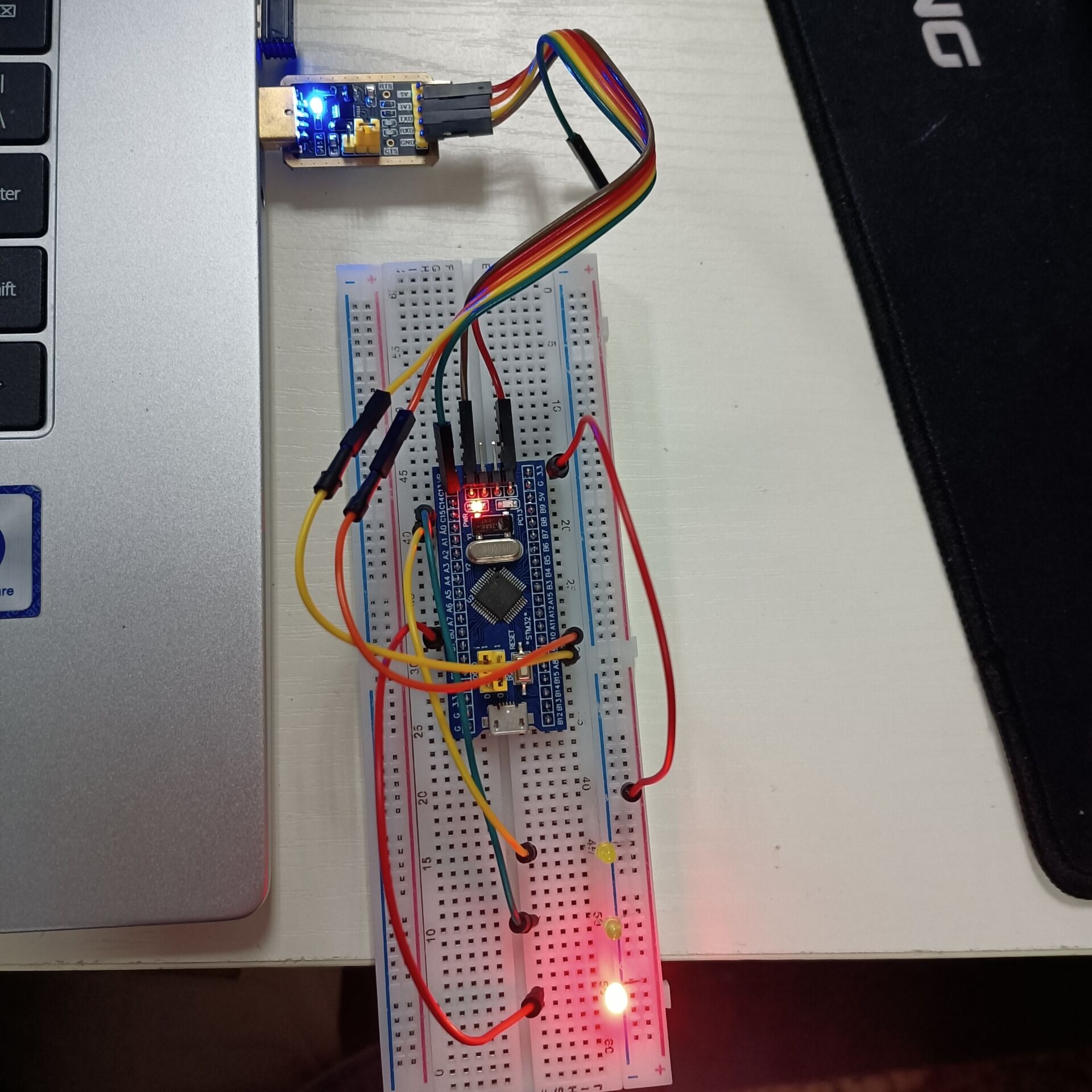
4. Connecting Circuits
For USB to TTL module and STM32F103C8T6 connection:
- GND — GND
- 3v3 — 3v3
- TXD — A10
- RXD — A9
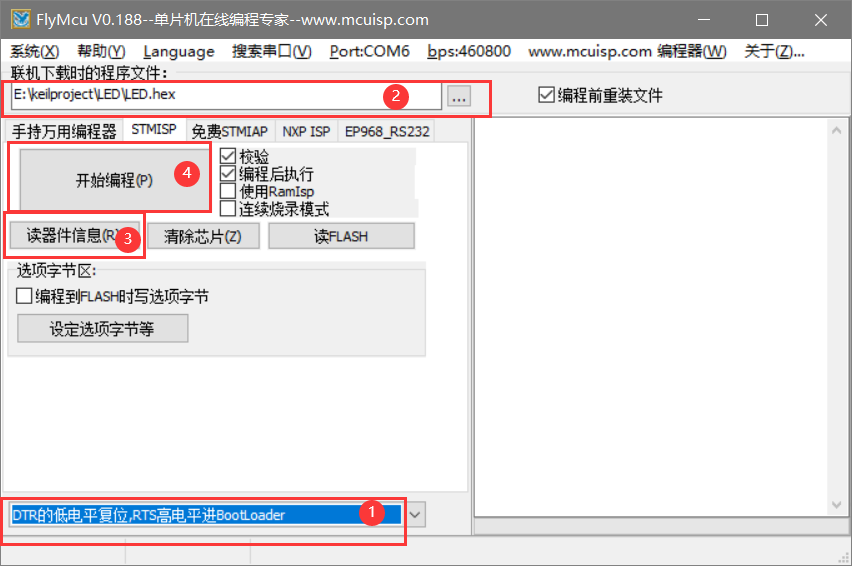
Connect to your computer, open FlyMcu, and upload the HEX file to STM32F103C8T6:
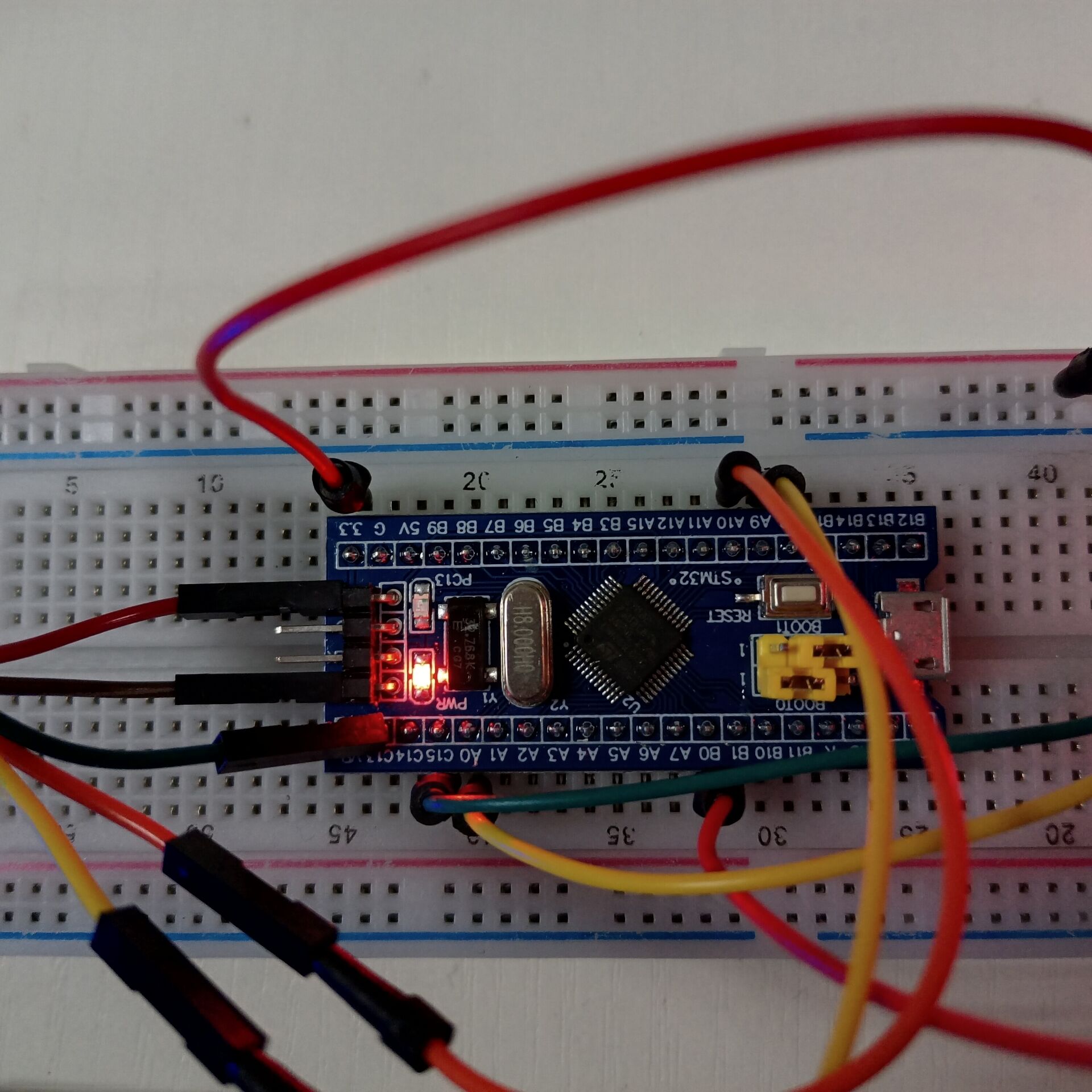
After burning to single-chip computer, the following results are obtained:
Run Results
5. Assembly Implementation
Code:
Stack_Size EQU  0x00000400;????

                AREA    STACK, NOINIT, READWRITE, ALIGN=3 ;NOINIT: = NO Init,?????READWRITE : ??,???ALIGN =3 : 2^3 ??,?8?????
Stack_Mem       SPACE   Stack_Size
__initial_sp


                AREA    RESET, DATA, READONLY

__Vectors       DCD     __initial_sp               ; Top of Stack
                DCD     Reset_Handler              ; Reset Handler


                AREA    |.text|, CODE, READONLY

                THUMB
                REQUIRE8
                PRESERVE8

                ENTRY
Reset_Handler
				bl LED_Init;bl:??????????????????,????(PC)?????LR???
MainLoop		BL LED_ON_B
                BL Delay
                BL LED_OFF_B
                BL Delay
				BL LED_ON_C
                BL Delay
                BL LED_OFF_C
                BL Delay
				BL LED_ON_A
                BL Delay
                BL LED_OFF_A
                BL Delay


                B MainLoop;B:??????
LED_Init;LED???
                PUSH {R0,R1, LR};R0,R1,LR???????
                ;????
                LDR R0,=0x40021018;LDR???????????(??R0)?
                ORR R0,R0,#0x1c
                LDR R1,=0x40021018
                STR R0,[R1]


                ;???GPIOA_CRL
                LDR R0,=0x40010800
                BIC R0,R0,#0x0fffffff;BIC ???????,????
                LDR R1,=0x40010800
                STR R0,[R1]

                LDR R0,=0x40010800
                ORR R0,#0x00000001
                LDR R1,=0x40010800
                STR R0,[R1]
                ;?PA0?1
                MOV R0,#0x01
                LDR R1,=0x4001080C
                STR R0,[R1]


                ;???GPIOB_CRL
                LDR R0,=0x40010C04
                BIC R0,R0,#0xffffff0f;BIC ???????,????
                LDR R1,=0x40010C04
                STR R0,[R1]

                LDR R0,=0x40010C04
                ORR R0,#0x00000020
                LDR R1,=0x40010C04
                STR R0,[R1]
                ;?PB0?1
                MOV R0,#0x200
                LDR R1,=0x40010C0C
                STR R0,[R1]


				 ;???GPIOC
                LDR R0,=0x40011004
                BIC R0,R0,#0x0fffffff
                LDR R1,=0x40011004
                STR R0,[R1]

                LDR R0,=0x40011004
                ORR R0,#0x20000000
                LDR R1,=0x40011004
                STR R0,[R1]
                ;?PC15?1
                MOV R0,#0x8000
                LDR R1,=0x4001100C
                STR R0,[R1]

                POP {R0,R1,PC};???????R0,R1,LR?????R0,R1,PC
LED_ON_A
                PUSH {R0,R1, LR}

                MOV R0,#0x00
                LDR R1,=0x4001080C
                STR R0,[R1]

                POP {R0,R1,PC}

LED_OFF_A
                PUSH {R0,R1, LR}

                MOV R0,#0x01
                LDR R1,=0x4001080C
                STR R0,[R1]

                POP {R0,R1,PC}
LED_ON_B;??
                PUSH {R0,R1, LR}

                MOV R0,#0x000
                LDR R1,=0x40010C0C
                STR R0,[R1]

                POP {R0,R1,PC}

LED_OFF_B;??
                PUSH {R0,R1, LR}

                MOV R0,#0x200
                LDR R1,=0x40010C0C
                STR R0,[R1]

                POP {R0,R1,PC}
LED_ON_C;??
                PUSH {R0,R1, LR}

                MOV R0,#0x0000
                LDR R1,=0x4001100C
                STR R0,[R1]

                POP {R0,R1,PC}

LED_OFF_C;??
                PUSH {R0,R1, LR}

                MOV R0,#0x8000
                LDR R1,=0x4001100C
                STR R0,[R1]

                POP {R0,R1,PC}

Delay
                PUSH {R0,R1, LR}

                MOVS R0,#0
                MOVS R1,#0
                MOVS R2,#0

DelayLoop0
                ADDS R0,R0,#1

                CMP R0,#330
                BCC DelayLoop0

                MOVS R0,#0
                ADDS R1,R1,#1
                CMP R1,#330
                BCC DelayLoop0

                MOVS R0,#0
                MOVS R1,#0
                ADDS R2,R2,#1
                CMP R2,#15
                BCC DelayLoop0


                POP {R0,R1,PC}
                NOP
				END
The steps for building a project are consistent with C, except for the.s type when creating a new file. Then repeat the operation to get the same result.
6. Summary
This experiment lights up LED just like HELLO WORLD, which is the most basic thing for embedded programming. We have learned about the operation of GPIO registers through this experiment, and believe that this experiment will lay a very important foundation in the next experiments.
7. References
STM32 F103 Lighting LED Streaming Light (STM32 Getting Started)
2. GPIO Output Operation of STM32
[STM32] GPIO-related configuration registers, library functions, bitwise operations (example: STM32 controls the horselight)
Wildfire Product Data Download Center