1, Initialization settings of GPIO port: clock configuration, I / O mode setting and maximum rate setting
1. Because the pins to be operated by the water flow lamp are all on the GPIO port, it belongs to the AHB bus according to the system structure diagram, so the reset and time control of the port to be used are controlled by RCC.
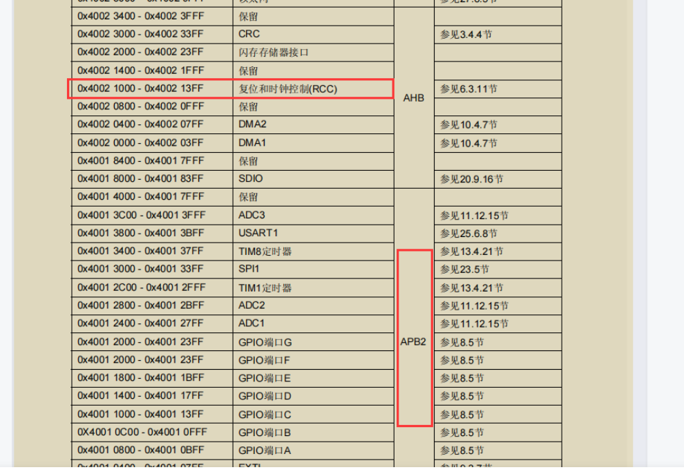
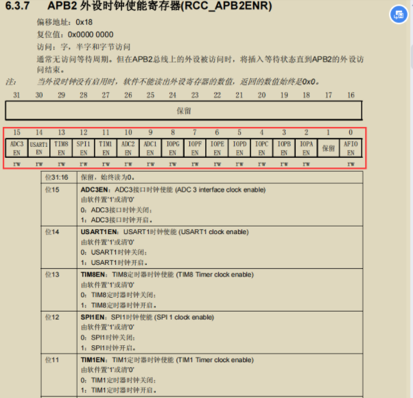
2. Skip to the peripheral clock enable register. The offset is 0x18. In the previous table, you can see that the starting address is 0x4002 1000 and the offset is 0x18, so the address of the register is 0x4002 1018
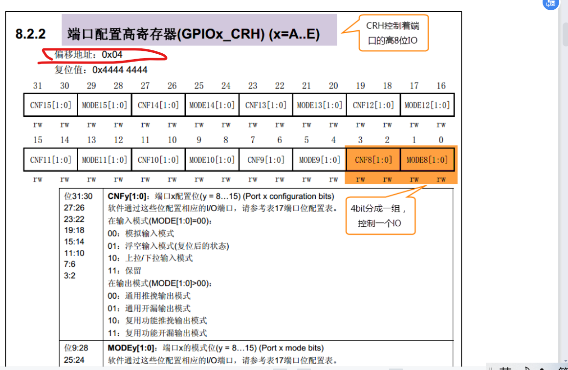
3. Then, configure the port configuration register, which is very critical. It can be found that the clock enable register above is for an area, and the pin cannot be determined. This register determines the pin. There are two port configuration registers, namely port configuration low register (CRL) and port configuration high register (CRH), One port is configured every four bits. For example, 11 01 is to select the on function, 01 is to select the mode and determine the maximum speed, but there is one difference. The offset address of the low register is 0x00 and the offset address of the high register is 0x04
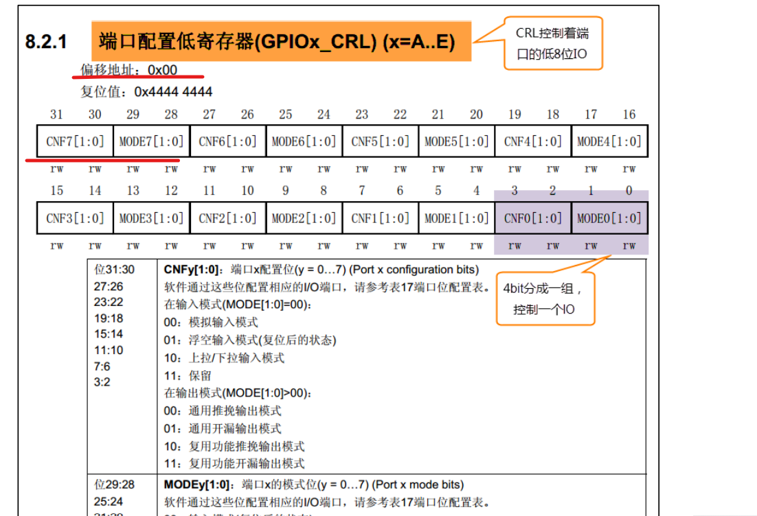
4. Taking PC15 as an example, the corresponding port configurator is GPIOA_ The CRL address is the base address + upper offset of GPIOA, which is 0x40011004 ` `, and this port needs to be turned on. Therefore, to make the corresponding bit the corresponding value, here is 0x30000000. Set the push-pull output and the maximum speed to 2Mhz. The following is the corresponding code
#define GPIOC_CRL	*((unsigned volatile int*)0x40011004)
GPIOC_CRL=0x30000000;		//PC15 push pull output, 2Mhz
5. Next, configure the port output register (ORD). You can see that the offset is 0xc, so the address of the register is equal to the base address of the port plus the offset. Assign a value in the corresponding bit to control the output voltage. 0 is the low voltage and 1 is the high voltage. Take PA7 pin as an example. If you want to output a high voltage, you need to assign 1 in the eighth bit
#define	GPIOA_ORD	*((unsigned volatile int*)0x4001080C)
GPIOA_ORD|=1<<7;			//Set the initial light to on
2, C language implementation of water lamp
1. Use keil to create a new project, which will not be referenced: C language program assembly of stm32 based on MDK
2. build compiler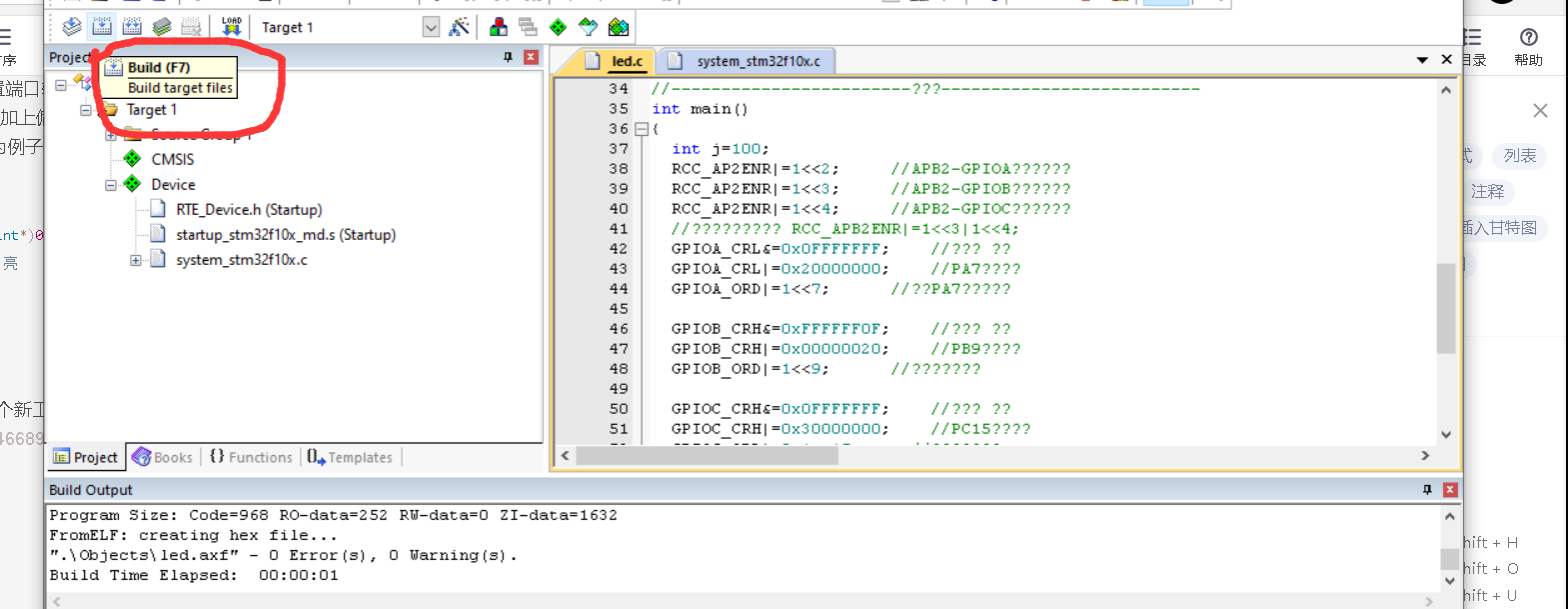
3. Use mcuisp software to burn the program to the minimum version. First select the. hex file generated by compilation, and then click Start compilation. You can also read the device information before compiling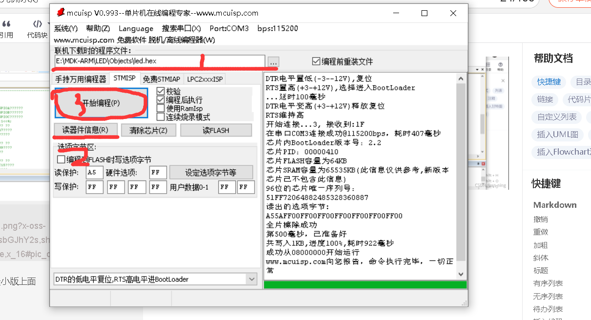
4. After the burning is successful, connect the wire as shown in the figure to turn on the LED light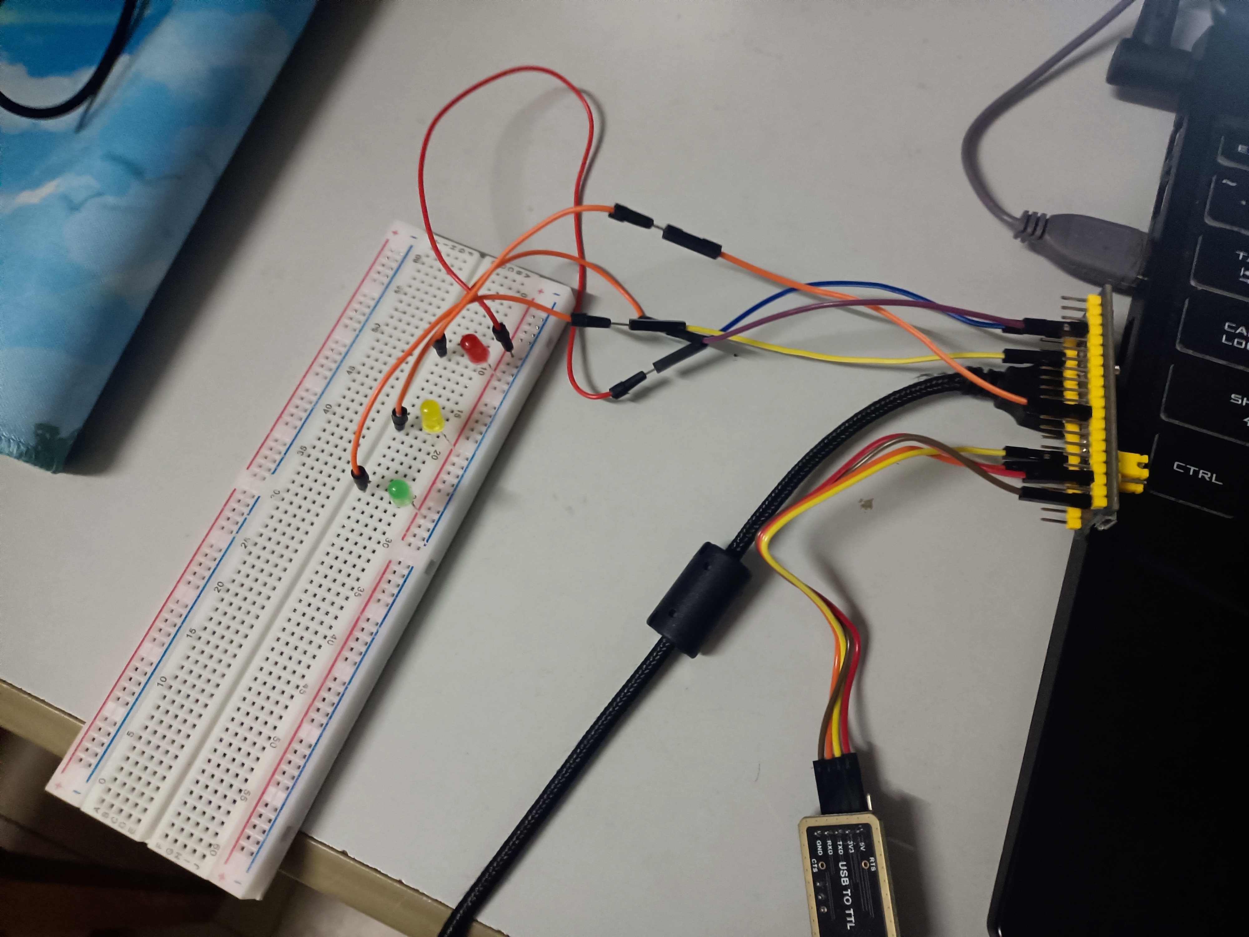
5. Operation results
3, Assembly language to achieve LED lighting
1. When creating a new project, do not check Startup, otherwise the program will report an error
2. Compile assembly code
RCC_APB2ENR EQU 0x40021018;to configure RCC register,Clock,0x40021018 Is the clock address
GPIOC_CRH EQU 0x40011004;to configure GPIOC_CRH Register is the port configuration high register, and the offset address of the high bit is 0 x04
GPIOC_ORD EQU 0x4001100c;to configure GPIOC_ORD Register is the port output register, and the output is controlled here
GPIOA_CRL EQU 0x40010800;to configure GPIOC_CRH Register is the port configuration high register, and the offset address of the high bit is 0 x04
GPIOA_ORD EQU 0x4001080C;to configure GPIOC_ORD Register is the port output register, and the output is controlled here
GPIOB_CRH EQU 0x40010C04;to configure GPIOC_CRH Register is the port configuration high register, and the offset address of the high bit is 0 x04
GPIOB_ORD EQU 0x40010C0C;to configure GPIOC_ORD Register is the port output register, and the output is controlled here
Stack_Size EQU  0x00000400;Stack size
;Assign a stack Segment, which is uninitialized, readable and writable, aligned by 8 bytes. Assign a size of Stack_Size And make the address of the top of the stack__initial_sp.
                AREA    STACK, NOINIT, READWRITE, ALIGN=3 ;NOINIT:  = NO Init,Not initialized. READWRITE : Readable and writable. ALIGN =3 : 2^3 Alignment, i.e. 8-byte alignment.
Stack_Mem       SPACE   Stack_Size
__initial_sp


                AREA    RESET, DATA, READONLY

__Vectors       DCD     __initial_sp               ; Top of Stack
                DCD     Reset_Handler              ; Reset Handler


                AREA    |.text|, CODE, READONLY

                THUMB
                REQUIRE8
                PRESERVE8

                ENTRY
Reset_Handler
				bl LED_Init;bl: Jump instruction with link. When using this instruction to jump, the current address(PC)It will be sent automatically LR register
MainLoop        BL LED_ON_C
                BL Delay
                BL LED_OFF_C
                BL Delay
				BL LED_ON_A
                BL Delay
                BL LED_OFF_A
                BL Delay
				BL LED_ON_B
                BL Delay
                BL LED_OFF_B
                BL Delay

                B MainLoop;B:Unconditional jump.
LED_Init;LED initialization
                PUSH {R0,R1, LR};R0,R1,LR Put the values in the stack

                LDR R0,=RCC_APB2ENR;LDR Is to load the address into the register(such as R0).
                ORR R0,R0,#0x1c;ORR operates by bit or, 11100 sets the second position of R0 to 1, and other bits remain unchanged
                LDR R1,=RCC_APB2ENR
                STR R0,[R1];STR Is to store the value in the address indicated by the register r0 The value stored in rcc register
				;The above part of the assembly code controls the clock


                ;initialization GPIOA part
                LDR R0,=GPIOA_CRL
                BIC R0,R0,#0x0fffffff;BIC reverses the immediate data first, and then compares it by bit
                LDR R1,=GPIOA_CRL
                STR R0,[R1]
                ;The above code is initialization CPIOC_CRH
                LDR R0,=GPIOA_CRL
                ORR R0,#0x20000000; pc15 is turned on, so it is 2, which is 0100. It is a push-pull output mode, and the maximum speed is 2mhz
                LDR R1,=GPIOA_CRL
                STR R0,[R1]
				;GPIOC Port configuration high register configuration is completed, that is CPIOA_CRH After the configuration is completed, the output mode of the port is determined, and the unused ones are set to the state after reset, which is 0100, so the output of the above processing is 4
                ;take PC15 Set 1
                MOV R0,#0x80;  The binary is 0b1000 0000, and the 7th bit is the output voltage of a7 pin
                LDR R1,=GPIOA_ORD ;from r1 control ord register
                STR R0,[R1] ;take ord The value of the register becomes r0 Value of

				 ;initialization GPIOB part
                LDR R0,=GPIOB_CRH
                BIC R0,R0,#0xffffff0f;BIC reverses the immediate value first, and then combines it by bit. It uses b9, so it sets the second position to zero
                LDR R1,=GPIOB_CRH
                STR R0,[R1]
                ;The above code is initialization CPIOC_CRH
                LDR R0,=GPIOB_CRH
                ORR R0,#0x00000020; pc15 is turned on, so it is 2, which is 0100. It is a push-pull output mode, and the maximum speed is 2mhz
                LDR R1,=GPIOB_CRH
                STR R0,[R1]
				;GPIOC Port configuration high register configuration is completed, that is CPIOA_CRH After the configuration is completed, the output mode of the port is determined, and the unused ones are set to the state after reset, which is 0100, so the output of the above processing is 4
                ;take PC15 Set 1
                MOV R0,#0x200;  The binary is 0b10 0000 0000, and the 16th bit is the output voltage of b9 pin
                LDR R1,=GPIOB_ORD ;from r1 control ord register
                STR R0,[R1] ;take ord The value of the register becomes r0 Value of

				 ;initialization GPIOC part
                LDR R0,=GPIOC_CRH
                BIC R0,R0,#0x0fffffff;BIC reverses the immediate number first, and then presses the bit and, that is, sets all 32 bits to zero
                LDR R1,=GPIOC_CRH
                STR R0,[R1]
                ;The above code is initialization CPIOC_CRH
                LDR R0,=GPIOC_CRH
                ORR R0,#0x20000000; pc15 is turned on, so it is 2, which is 0100. It is a push-pull output mode, and the maximum speed is 2mhz
                LDR R1,=GPIOC_CRH
                STR R0,[R1]
				;GPIOC Port configuration high register configuration is completed, that is CPIOA_CRH After the configuration is completed, the output mode of the port is determined, and the unused ones are set to the state after reset, which is 0100, so the output of the above processing is 4
                ;take PC15 Set 1
                MOV R0,#0x8000;  The binary is 0b1000 0000, and the 16th bit is the output voltage of c15 pin
                LDR R1,=GPIOC_ORD ;from r1 control ord register
                STR R0,[R1] ;take ord The value of the register becomes r0 Value of

                POP {R0,R1,PC};Store the previously stored in the stack R0,R1,LR Value returned to R0,R1,PC
LED_ON_A;Light up
                PUSH {R0,R1, LR}

                MOV R0,#0x00 ; The binary is 0b0000, the 16th bit is 0, which will be used as the output voltage of pc15
                LDR R1,=GPIOA_ORD ;take GPIOC Address assignment r1
                STR R0,[R1];take r0 The value assigned to GPIOC_ORD in

                POP {R0,R1,PC}

LED_OFF_A;Turn off the light
                PUSH {R0,R1, LR}

                MOV R0,#0x80 ; The binary is 0b 1000 0000, the 16th bit is 1, which will be used as the output voltage of pc15
                LDR R1,=GPIOA_ORD ;take GPIOC Address assignment r1
                STR R0,[R1] ;[]It refers to the operation on the address inside, so it is to r0 Value assignment GPIOC_ORD

                POP {R0,R1,PC}
LED_ON_B;Light up
                PUSH {R0,R1, LR}

                MOV R0,#0x000 ; The binary is 0b0000, the 16th bit is 0, which will be used as the output voltage of pc15
                LDR R1,=GPIOB_ORD ;take GPIOC Address assignment r1
                STR R0,[R1];take r0 The value assigned to GPIOC_ORD in

                POP {R0,R1,PC}

LED_OFF_B;Turn off the light
                PUSH {R0,R1, LR}

                MOV R0,#0x200 ; The binary is 0b 1000 0000, the 16th bit is 1, which will be used as the output voltage of pc15
                LDR R1,=GPIOB_ORD ;take GPIOC Address assignment r1
                STR R0,[R1] ;[]It refers to the operation on the address inside, so it is to r0 Value assignment GPIOC_ORD

                POP {R0,R1,PC}
LED_ON_C;Light up
                PUSH {R0,R1, LR}

                MOV R0,#0x0000 ; The binary is 0b0000, the 16th bit is 0, which will be used as the output voltage of pc15
                LDR R1,=GPIOC_ORD ;take GPIOC Address assignment r1
                STR R0,[R1];take r0 The value assigned to GPIOC_ORD in

                POP {R0,R1,PC}

LED_OFF_C;Turn off the light
                PUSH {R0,R1, LR}

                MOV R0,#0x8000 ; The binary is 0b 1000 0000, the 16th bit is 1, which will be used as the output voltage of pc15
                LDR R1,=GPIOC_ORD ;take GPIOC Address assignment r1
                STR R0,[R1] ;[]It refers to the operation on the address inside, so it is to r0 Value assignment GPIOC_ORD

                POP {R0,R1,PC}

Delay
                PUSH {R0,R1, LR}

                MOVS R0,#0
                MOVS R1,#0
                MOVS R2,#0

DelayLoop0
                ADDS R0,R0,#1

                CMP R0,#330
                BCC DelayLoop0

                MOVS R0,#0
                ADDS R1,R1,#1
                CMP R1,#330
                BCC DelayLoop0 ;No carry

                MOVS R0,#0
                MOVS R1,#0
                ADDS R2,R2,#1
                CMP R2,#15
                BCC DelayLoop0


                POP {R0,R1,PC}
                NOP
				END
3. Compiling and burning: the process is the same as that of C language
4. Operation effect
Reference blog: STM32F103C8T6 realizes running water lamp