Catalog
3. Use interruption to light up LED
4. Interrupt for Serial Communication
1. Interruption
1. What is an interruption
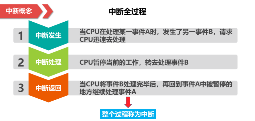
Interrupt refers to the process in which a computer runs, when some unexpected circumstances require host intervention, the machine can automatically stop the running program and transfer to the program dealing with the new situation, and then return to the original suspended program to continue running after processing.
2. Break the whole process
3. Role of interruption

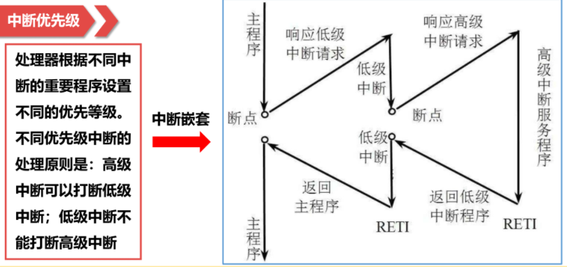
4. Interrupt Priority
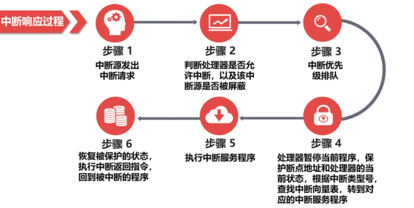
5. Interrupt response process
2. Interrupt System of STM32
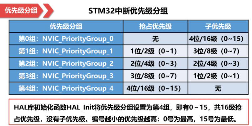
1. Priority Grouping
2. Programming steps
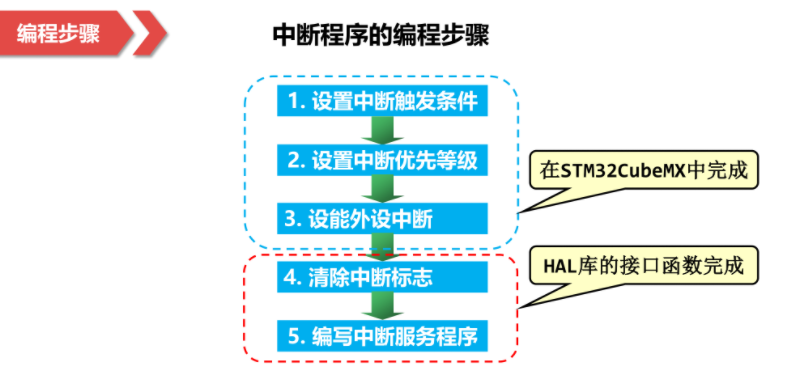
In the above process, you can use STM32cubeMX to complete,
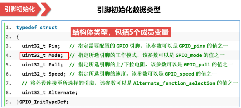
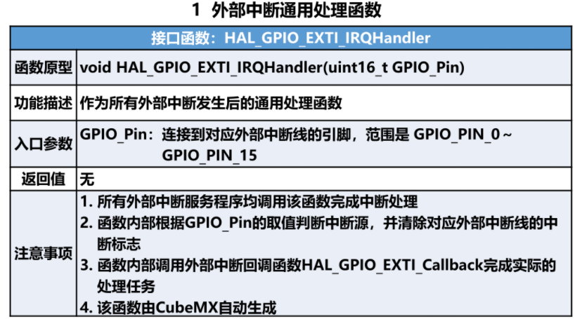
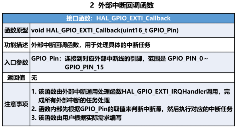
3. Specific functions
3. Use interruption to light up LED
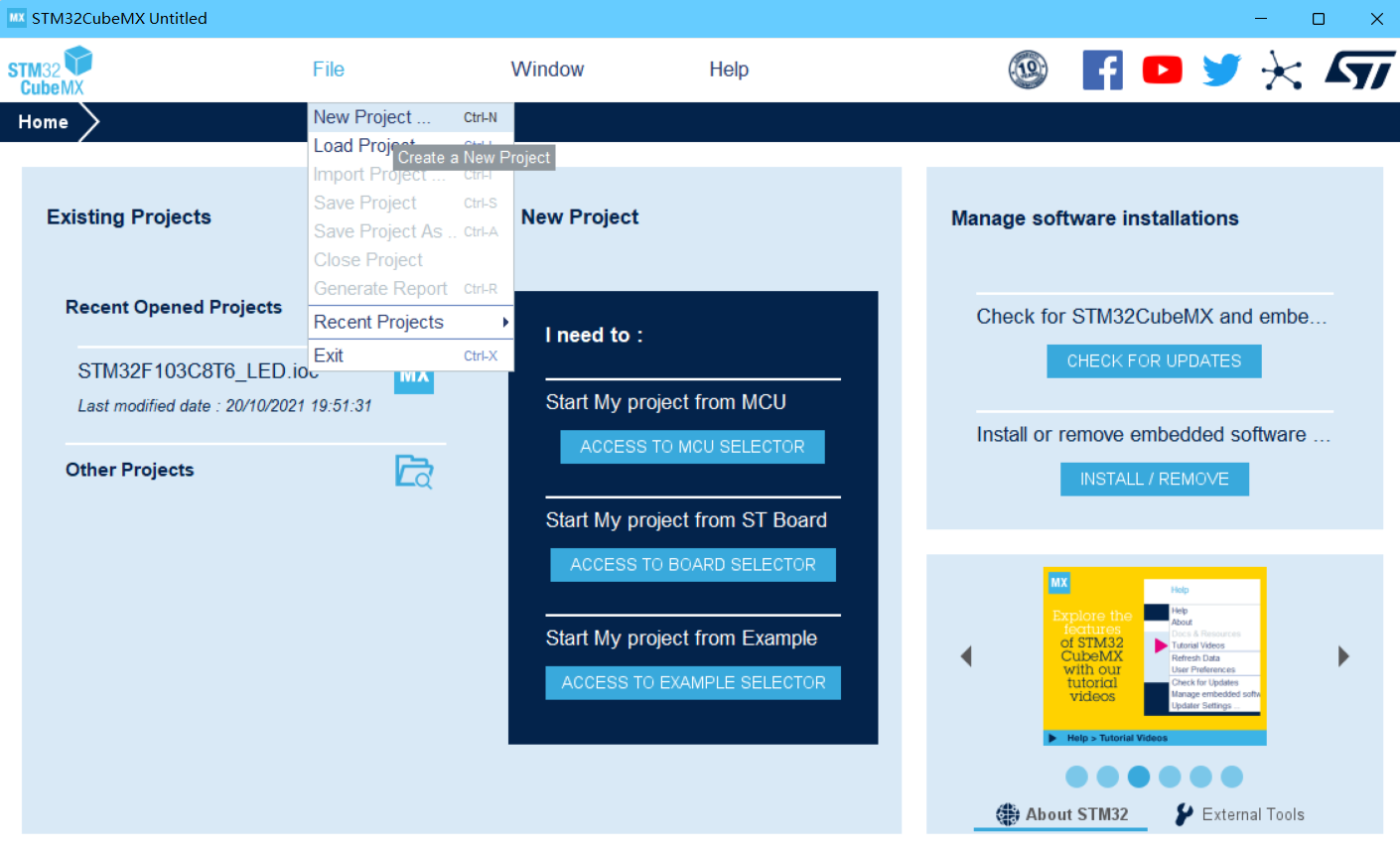
First create the project using STM32cubeMX, click File->New Project
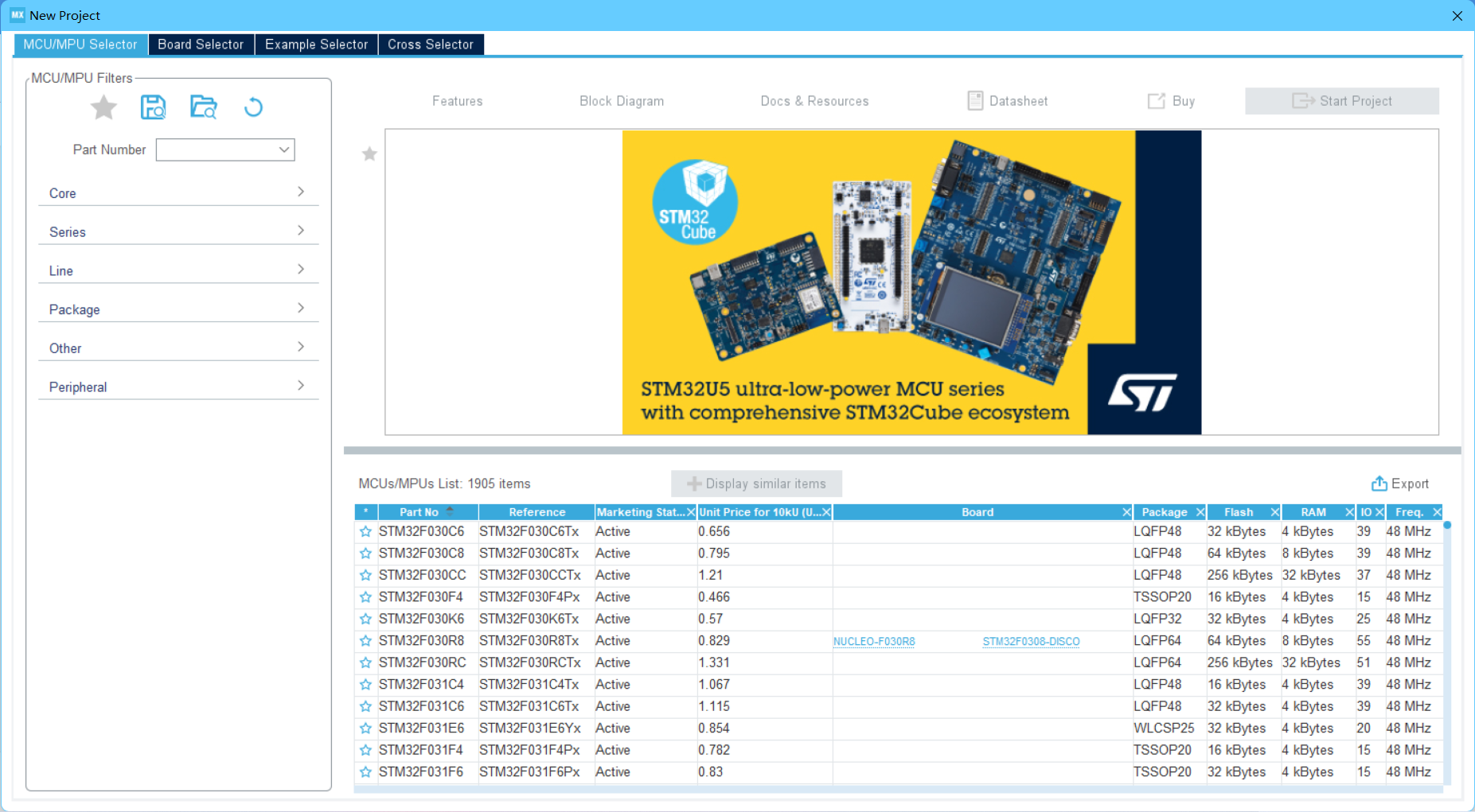
Select the stm32 model I'm using, STM32F103C8T6
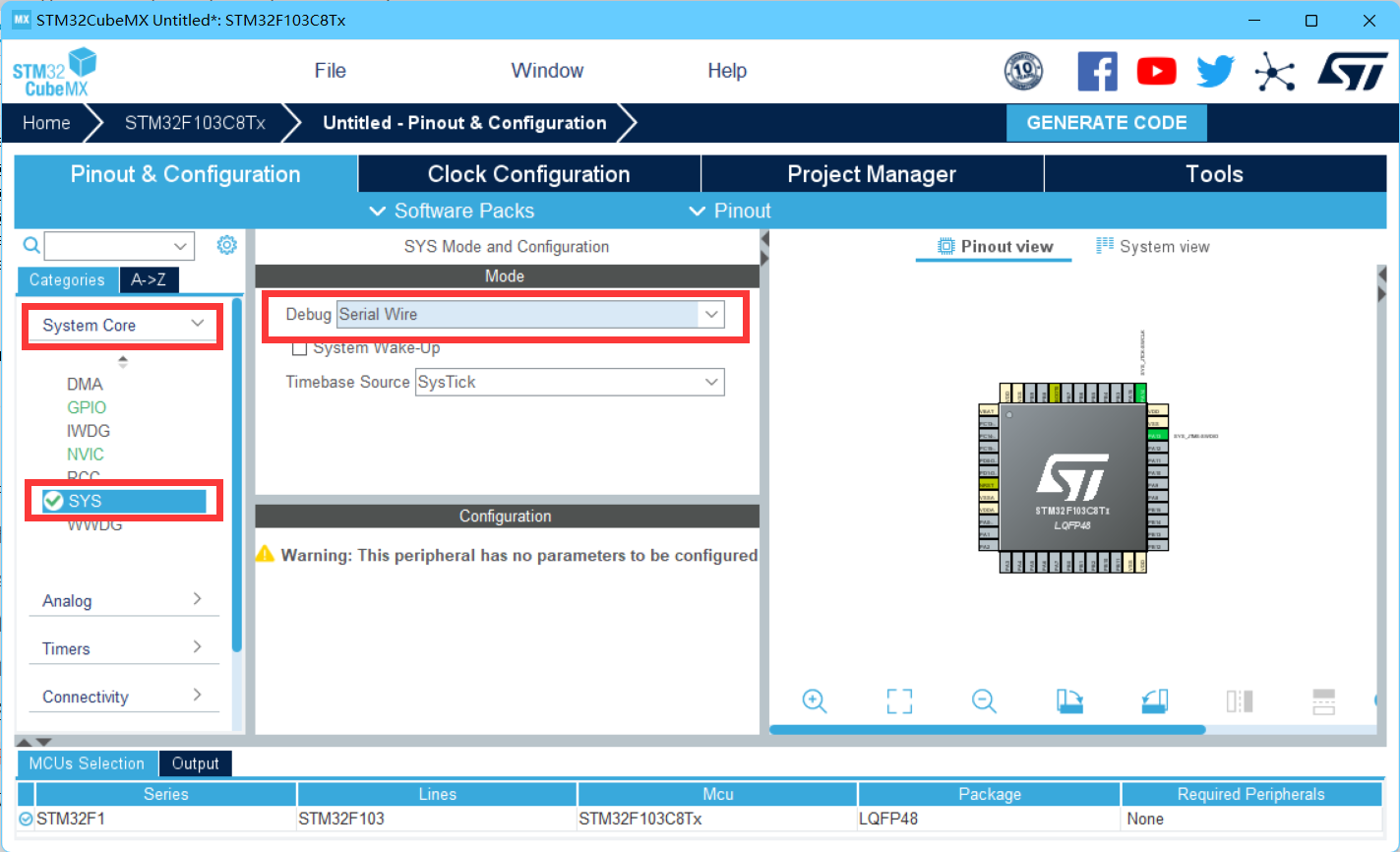
Then select sys in the system core to modify debug to serial wire
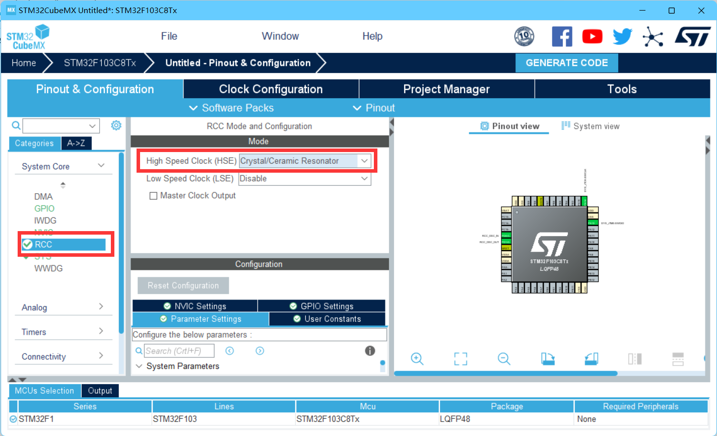
Then select Crystal/Ceramic Resonator for HSE in Rcc
Select PB0 as the external interrupt trigger, GPIO_EXIT0, PA1 selected as GPIO_output to control LED

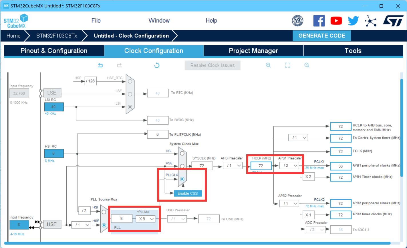
Select Clock Configuration, then change to PLCLK, maximum crystal frequency to 72MHz
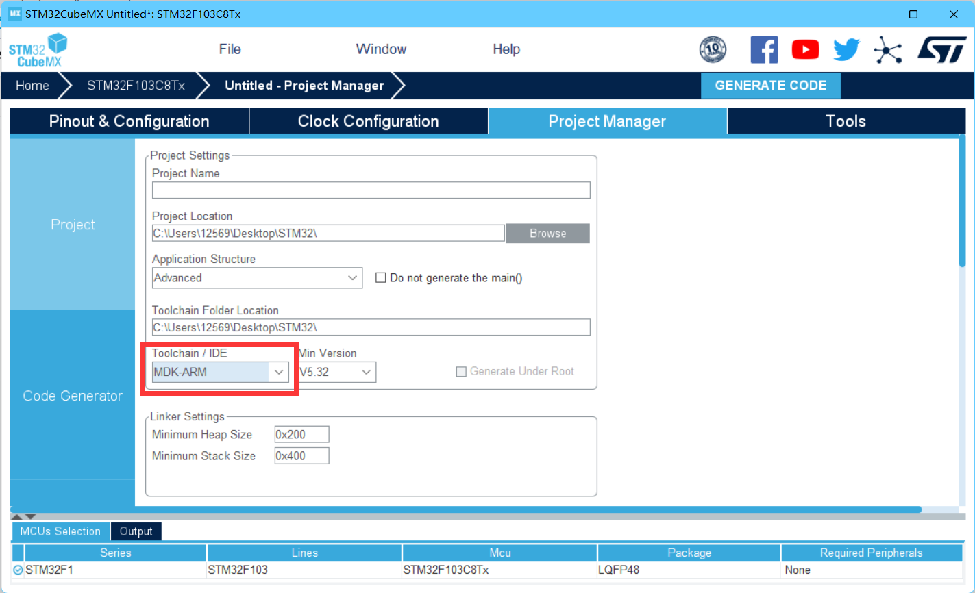
Then modify the IDE to MDK-ARM from project manager, and choose the project name and directory
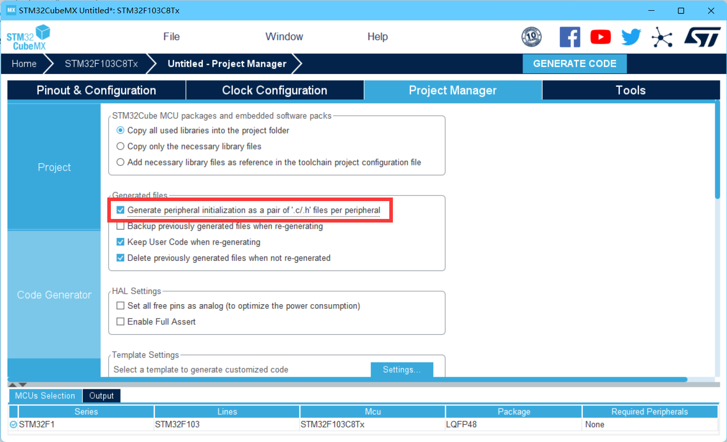
Then select Generate Initialization File in Code Generator
Click GENERATE CODE in the upper right corner to create the project successfully
Add the following functions to main.c
void HAL_GPIO_EXTI_Callback(uint16_t GPIO_Pin)
{
	GPIO_PinState b0_pin = HAL_GPIO_ReadPin(GPIOB, GPIO_PIN_0); \\read PB0
	b0_pin=1-b0_pin;
	switch (GPIO_Pin)
		{
		case GPIO_PIN_0:
			HAL_GPIO_WritePin(GPIOA, GPIO_PIN_1,1-b0_pin); \\writd PA1=PB0
			break;
		}
}
Burning to stm32f103c8t6 using serial port or stlink, the serial burning method is detailed in
From Knowing Serial Port to Serial Port Communication_ pink_lemon's Blog - CSDN Blog
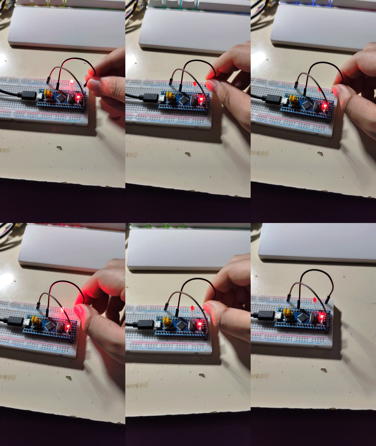
The connection method is as follows
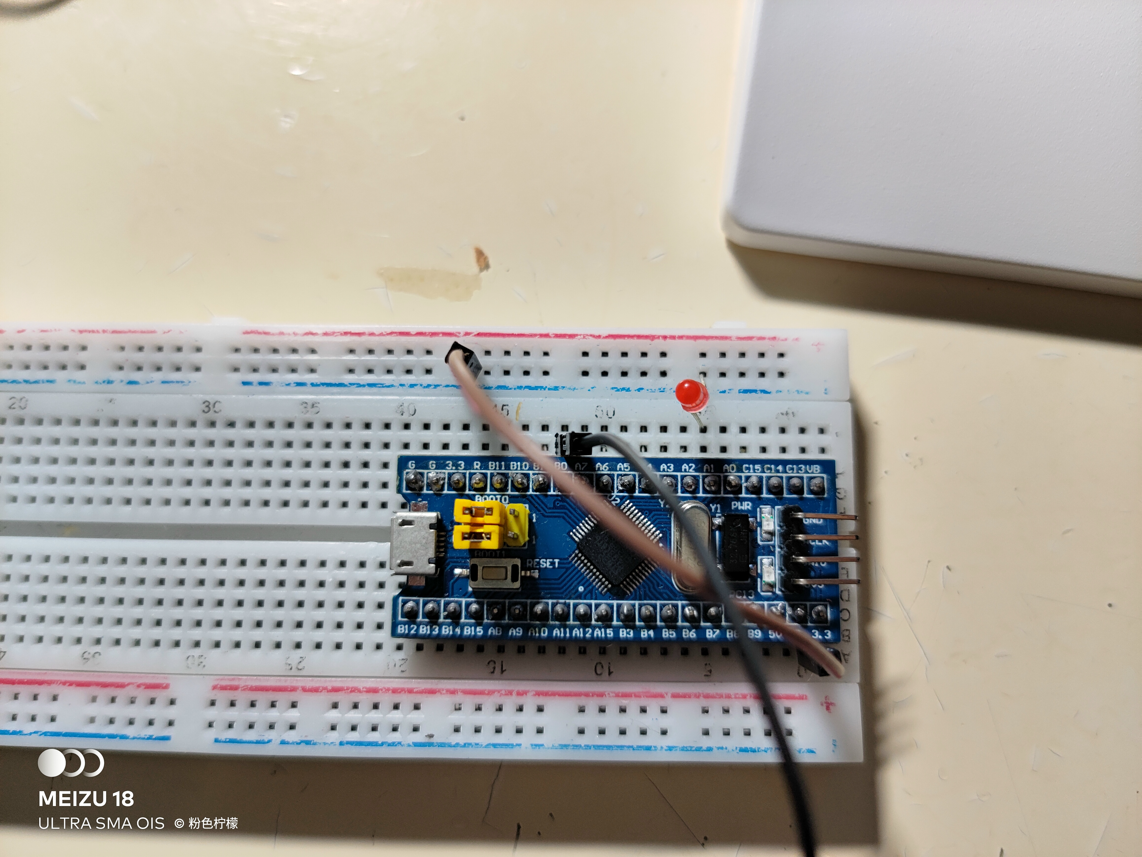
Power on, the final result is as follows
4. Interrupt for Serial Communication
Still use stm32cubeMX to generate the project, adding one step as above
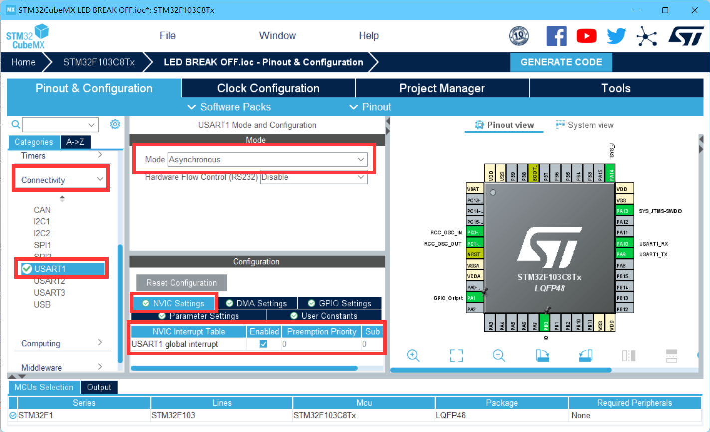
Select UASRT1, modify Model to asynchronous in connectivity, change model to asynchronous communication, select NVIC Setting below, and check enabled
After creating a new project, add a definition after the header file of main.c
uint8_t aRxBuffer;//Receive Buffer Interrupt
uint8_t Uart1_RxBuff[256];//Receive Buffer
uint8_t Uart1_Rx_Cnt=0;//Receive Buffer Count
uint8_t cAlmStr[]=" data max is 255";
Then override HAL_UART_RxCpltCallback function
void HAL_UART_RxCpltCallback(UART_HandleTypeDef *huart)
{
  if(Uart1_Rx_Cnt >= 255)  //Overflow Judgment
	{
		Uart1_Rx_Cnt = 0;
		memset(Uart1_RxBuff,0x00,sizeof(Uart1_RxBuff));
		HAL_UART_Transmit(&huart1, (uint8_t *)&cAlmStr, sizeof(cAlmStr),0xFFFF);
	}
	else
	{
		Uart1_RxBuff[Uart1_Rx_Cnt++] = aRxBuffer;   //Receive Data Transfer

		if((Uart1_RxBuff[Uart1_Rx_Cnt-1] == 0x0A)||(Uart1_RxBuff[Uart1_Rx_Cnt-2] == 0x0D)) //Judgement End Position
		{
			HAL_UART_Transmit(&huart1, (uint8_t *)&Uart1_RxBuff, Uart1_Rx_Cnt,0xFFFF); //Send the information you receive
			Uart1_Rx_Cnt = 0;
			memset(Uart1_RxBuff,0x00,sizeof(Uart1_RxBuff)); //Empty Array
		}
	}

	HAL_UART_Receive_IT(&huart1, (uint8_t *)&aRxBuffer, 1);   //Re-open Receive Interrupt

}
Then add a receive interrupt function to the main function
HAL_UART_Receive_IT(&huart1,(uint8_t*)&aRxBuffer,1);
Burn into stm32 after generating hex file
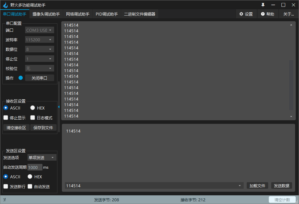
Run the result, and you can see that the send and return are the same, but be careful to select a new line or follow the input string with an enter key
V. Summary
There are many ways to interrupt, including hardware interrupt and software interrupt, interrupt mode also has priority, should be noted when using
6. References
Control LED lights by interruption (STMF103C8+HAL library)_ junseven164's Blog - CSDN Blog