STM32F103 - timer encoder mode and advanced timer output complementary PWM signals
When STM32 is just used, the encoder speed is calculated by using the input capture interrupt to obtain the motor speed. After a period of learning, it is found that the motor speed is obtained by using the input capture interrupt. When the motor speed is not high, the motor speed can be well obtained, but when the motor speed is very high, STM32 will enter the interrupt frequently, MCU will spend a long time in interrupt processing, which will affect the normal operation of the system.
After understanding, using the encoder mode of STM32 timer, the motor speed can be obtained without input capture interrupt.
I am very grateful for the selfless sharing of the great God on the Internet, which makes me gain a lot and learn a lot.
How the encoder generates a and B two-phase signals and the basic knowledge of the timer encoder are not described here. You can see a lot of information on the Internet. Here we will focus on the difficulties of encoder mode. Personally, this picture is the most difficult part of the whole encoder mode. My personal understanding is: if there are two-phase encoder signals a and B, phase A is 90 degrees ahead of phase B. In the third case in the figure below: if the relative signal level signal is phase B signal, the phase B level is high, and the falling edge of a signal, the counter counts up once; At this time, the phase B level is low, and at this time, the rising edge of the a signal, the counter counts up once. If the relative signal level signal is a phase a signal, the phase a level is high, and the rising edge of phase B signal, the counter counts up once; At this time, the level of phase A is low, and at this time, the falling edge of phase B signal, the counter counts up once. Therefore, the counter counts 4 times in total, which improves the counting accuracy. In the later program, divide by 4 because the encoder mode adopts this frequency multiplication. (personal level is limited, please forgive me if you have any questions ~ thank you)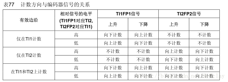
The following is the specific configuration of timer 2 encoder mode and timer 8 output complementary PWM signal and timer 3 interrupt:
(1) , turn on the clock and configure the two pins of timer 2 as floating input
(2) , the timer 2 is configured to the encoder mode, and the counter is counted when the A-phase and B-phase signals change.
(3) , set the initial value of timer 2 counter
(4) The timer 8 is configured to output two complementary PWM waves to control the motor
(5) , configure timer 3, interrupt every 0.05S, read the value of timer 2 counter and calculate the speed of encoder. And each interrupt updates the initial value of timer 2
//*****************Main function*****************//
#include "sys.h"
#include "delay.h"
#include "timer.h"
//#include "usart.h"
#include "SEGGER_RTT.h"


int16_t Signal_Fre = 0;


int main(void)
{
	delay_init();	    	 //Delay function initialization
	NVIC_PriorityGroupConfig(NVIC_PriorityGroup_2); 	 //Set NVIC interrupt packet 2: 2-bit preemption priority and 2-bit response priority
  //uart_init(115200); 	 // The serial port is initialized to 115200

	TIM8_PWM_Init(899,3);	 //PWM frequency = 72000000/900/4=20Khz
	TIM2_Encoder_Init(65535,0); //Timer 2 encoder mode
	TIM3_Int_Init(4999,719);//0.05s timer overflow interrupt

	TIM8_PWMStopGPIO_Init();
	delay_ms(10);
	SEGGER_RTT_printf(0,"Test \r\n");

  while(1)
	{

		TIM_SetCompare1(TIM8,450);
	  TIM_SetCompare2(TIM8,0);

		delay_ms(10);
	}
}

//**********Timer configuration****************//
#include "timer.h"
//#include "usart.h"
#include "SEGGER_RTT.h"

extern int16_t Signal_Fre;

///
//TIM2 -- encoder mode
//TIM3--0.05 second timing - calculate encoder speed
//TIM8--PWM complementary output
///


/***************TIM2 Initialization********************/
//General timer 2 -- encoder mode, PA0, PA1;
//arr: Auto reload value
//psc: clock pre division frequency
void TIM2_Encoder_Init(u16 arr,u16 psc)
{
    GPIO_InitTypeDef GPIO_InitStructure;
	TIM_TimeBaseInitTypeDef  TIM_TimeBaseStructure;
	TIM_ICInitTypeDef  TIM_ICInitStructure;

	RCC_APB1PeriphClockCmd(RCC_APB1Periph_TIM2, ENABLE);	//Enable timer 2 clock
	RCC_APB2PeriphClockCmd(RCC_APB2Periph_GPIOA, ENABLE);

	GPIO_InitStructure.GPIO_Mode=GPIO_Mode_IN_FLOATING;//Floating input
	GPIO_InitStructure.GPIO_Pin=GPIO_Pin_0;
	GPIO_InitStructure.GPIO_Speed=GPIO_Speed_50MHz;
	GPIO_Init(GPIOA,&GPIO_InitStructure);

	GPIO_InitStructure.GPIO_Mode=GPIO_Mode_IN_FLOATING;//Floating input
	GPIO_InitStructure.GPIO_Pin=GPIO_Pin_1;
	GPIO_InitStructure.GPIO_Speed=GPIO_Speed_50MHz;
	GPIO_Init(GPIOA,&GPIO_InitStructure);

	TIM_TimeBaseStructure.TIM_ClockDivision=TIM_CKD_DIV1;
	TIM_TimeBaseStructure.TIM_CounterMode=TIM_CounterMode_Up;
	TIM_TimeBaseStructure.TIM_Period=arr;
	TIM_TimeBaseStructure.TIM_Prescaler=psc;
	TIM_TimeBaseInit(TIM2,&TIM_TimeBaseStructure);

	TIM_EncoderInterfaceConfig(TIM2,TIM_EncoderMode_TI12,TIM_ICPolarity_BothEdge,TIM_ICPolarity_BothEdge); //Encoder Mode
	TIM_ICStructInit(&TIM_ICInitStructure);
	//TIM_ICInitStructure.TIM_Channel=TIM_Channel_1;
	TIM_ICInitStructure.TIM_ICFilter=6;
	//TIM_ICInitStructure.TIM_ICPolarity=TIM_ICPolarity_Rising;
	//TIM_ICInitStructure.TIM_ICPrescaler=TIM_ICPSC_DIV1;
	//TIM_ICInitStructure.TIM_ICSelection=TIM_ICSelection_DirectTI;
	TIM_ICInit(TIM2,&TIM_ICInitStructure);
	TIM_ClearFlag(TIM2,TIM_FLAG_Update);//Clear update flag bit
	//TIM_ITConfig(TIM2,TIM_IT_Update,ENABLE);
    TIM_ClearITPendingBit(TIM2,TIM_IT_Update); //Clear interrupt flag bit
	TIM_SetCounter(TIM2,32768);
    TIM_Cmd(TIM2,ENABLE);
}

/****************************TIM3 Initialization*********************************************/
void TIM3_Int_Init(u16 arr,u16 psc)
{
    TIM_TimeBaseInitTypeDef TIM_TimeBaseStructure;
    NVIC_InitTypeDef NVIC_InitStructure;

	RCC_APB1PeriphClockCmd(RCC_APB1Periph_TIM3,ENABLE);

    TIM_TimeBaseStructure.TIM_ClockDivision=TIM_CKD_DIV1;
	TIM_TimeBaseStructure.TIM_CounterMode=TIM_CounterMode_Up;
	TIM_TimeBaseStructure.TIM_Period=arr;
	TIM_TimeBaseStructure.TIM_Prescaler=psc;
	TIM_TimeBaseInit(TIM3,&TIM_TimeBaseStructure);

	TIM_ITConfig(TIM3,TIM_IT_Update,ENABLE ); //Enables the specified TIM3 interrupt and allows the update interrupt

    NVIC_InitStructure.NVIC_IRQChannel=TIM3_IRQn;
	NVIC_InitStructure.NVIC_IRQChannelCmd=ENABLE;
	NVIC_InitStructure.NVIC_IRQChannelPreemptionPriority=0;
	NVIC_InitStructure.NVIC_IRQChannelSubPriority=3;
    NVIC_Init(&NVIC_InitStructure);

	TIM_Cmd(TIM3,ENABLE);
}

/*********************************TIM3 Interrupt processing***************************************/
void TIM3_IRQHandler()
{
  if (TIM_GetITStatus(TIM3, TIM_IT_Update) != RESET)  //Check whether the TIM3 update interrupt occurs
	{
		Signal_Fre = TIM_GetCounter(TIM2);
	    Signal_Fre = (int)Signal_Fre * 20 / 4;  //The timer is interrupted once in 0.05s, and the encoder mode is 4 times the frequency, and the speed of the encoder is calculated
		TIM_SetCounter(TIM2,32768);

		SEGGER_RTT_printf(0,"Signal_Fre=%d \r\n",Signal_Fre);
		SEGGER_RTT_printf(0,"TIM3IRQ \r\n");
		TIM_ClearITPendingBit(TIM3, TIM_IT_Update);  //Clear TIMx update interrupt flag
	}
}


/********************TIM8 Initialization***********************/
//TIM8 PWM section initialization
//CH1:PC6
//CH1N:PA7
//CH2:PC7
//CH2N:PB0
//CH3:PC8
//CH3N:PB1
//BKIN:PA7
//arr: Auto reload value
//psc: clock pre division frequency
void TIM8_PWM_Init(u16 arr,u16 psc)
{
	GPIO_InitTypeDef GPIO_InitStructure;
	TIM_TimeBaseInitTypeDef  TIM_TimeBaseStructure;
	TIM_OCInitTypeDef  TIM_OCInitStructure;
	TIM_BDTRInitTypeDef TIM_BDTRInitStructure;

	RCC_APB2PeriphClockCmd(RCC_APB2Periph_TIM8, ENABLE);	//Enable timer 8 clock

 	RCC_APB2PeriphClockCmd(RCC_APB2Periph_GPIOA | RCC_APB2Periph_GPIOB | RCC_APB2Periph_GPIOC , ENABLE);  //Enable GPIO peripheral function module clock

  //Set this pin as the multiplexing output function to output the PWM pulse waveform of TIM8 CH1 	 GPIOC.6
	GPIO_InitStructure.GPIO_Pin = GPIO_Pin_6; //TIM_CH1
	GPIO_InitStructure.GPIO_Mode = GPIO_Mode_AF_PP;  //Multiplexed push-pull output
	GPIO_InitStructure.GPIO_Speed = GPIO_Speed_50MHz;
	GPIO_Init(GPIOC, &GPIO_InitStructure);//Initialize GPIO

	//Set this pin as the multiplexing output function to output the PWM pulse waveform of TIM8 CH1N 	 GPIOA.7
	GPIO_InitStructure.GPIO_Pin = GPIO_Pin_7; //TIM_CH1N
	GPIO_InitStructure.GPIO_Mode = GPIO_Mode_AF_PP;  //Multiplexed push-pull output
	GPIO_InitStructure.GPIO_Speed = GPIO_Speed_50MHz;
	GPIO_Init(GPIOA, &GPIO_InitStructure);//Initialize GPIO

	//Set this pin as the multiplexing output function to output the PWM pulse waveform of TIM8 CH2 	 GPIOC.7
	GPIO_InitStructure.GPIO_Pin = GPIO_Pin_7; //TIM_CH2
	GPIO_InitStructure.GPIO_Mode = GPIO_Mode_AF_PP;  //Multiplexed push-pull output
	GPIO_InitStructure.GPIO_Speed = GPIO_Speed_50MHz;
	GPIO_Init(GPIOC, &GPIO_InitStructure);//Initialize GPIO

	//Set this pin as the multiplexing output function to output the PWM pulse waveform of TIM8 CH1N 	 GPIOB.0
	GPIO_InitStructure.GPIO_Pin = GPIO_Pin_0; //TIM_CH2N
	GPIO_InitStructure.GPIO_Mode = GPIO_Mode_AF_PP;  //Multiplexed push-pull output
	GPIO_InitStructure.GPIO_Speed = GPIO_Speed_50MHz;
	GPIO_Init(GPIOB, &GPIO_InitStructure);//Initialize GPIO

  //Set this pin as the multiplexing output function to output the PWM pulse waveform of TIM8 CH3 	 GPIOC.8
	GPIO_InitStructure.GPIO_Pin = GPIO_Pin_8; //TIM_CH3
	GPIO_InitStructure.GPIO_Mode = GPIO_Mode_AF_PP;  //Multiplexed push-pull output
	GPIO_InitStructure.GPIO_Speed = GPIO_Speed_50MHz;
	GPIO_Init(GPIOC, &GPIO_InitStructure);//Initialize GPIO

	//Set this pin as the multiplexing output function to output the PWM pulse waveform of TIM8 CH3N 	 GPIOB.1
	GPIO_InitStructure.GPIO_Pin = GPIO_Pin_1; //TIM_CH3N
	GPIO_InitStructure.GPIO_Mode = GPIO_Mode_AF_PP;  //Multiplexed push-pull output
	GPIO_InitStructure.GPIO_Speed = GPIO_Speed_50MHz;
	GPIO_Init(GPIOB, &GPIO_InitStructure);//Initialize GPIO

  //Brake pin PA6
	GPIO_InitStructure.GPIO_Pin = GPIO_Pin_6; //BKIN
	GPIO_InitStructure.GPIO_Mode = GPIO_Mode_AF_PP;  //Multiplexed push-pull output
	GPIO_InitStructure.GPIO_Speed = GPIO_Speed_50MHz;
	GPIO_Init(GPIOA, &GPIO_InitStructure);//Initialize GPIO

   //Initialize TIM1
	TIM_TimeBaseStructure.TIM_Period = arr; //Sets the value of the auto reload register cycle of the load activity at the next update event
	TIM_TimeBaseStructure.TIM_Prescaler =psc; //Sets the prescaled value used as the divisor of TIMx clock frequency
	TIM_TimeBaseStructure.TIM_ClockDivision = TIM_CKD_DIV1; //Set clock division: TDTS = Tck_tim
	TIM_TimeBaseStructure.TIM_CounterMode = TIM_CounterMode_Up;  //TIM up count mode
	TIM_TimeBaseInit(TIM8, &TIM_TimeBaseStructure); //According to Tim_ The parameter specified in timebaseinitstruct initializes the time base unit of TIMx

	//Initialize TIM1 PWM mode
	TIM_OCInitStructure.TIM_OCMode = TIM_OCMode_PWM1; //Select timer mode: TIM pulse width modulation mode 1
 	TIM_OCInitStructure.TIM_OutputState = TIM_OutputState_Enable; //Compare output enable
	TIM_OCInitStructure.TIM_OutputNState = TIM_OutputNState_Enable; //Complementary comparison output enable
	TIM_OCInitStructure.TIM_Pulse = 0;  //Value of duty cycle CCR
	TIM_OCInitStructure.TIM_OCPolarity = TIM_OCPolarity_High; //Output polarity: TIM output has high polarity
	//TIM_OCInitStructure.TIM_OCPolarity = TIM_OCPolarity_Low; // Output polarity: Tim output is relatively low polarity
	TIM_OCInitStructure.TIM_OCNPolarity = TIM_OCNPolarity_High; //Complementary output polarity: TIM output has relatively high polarity
	//TIM_OCInitStructure.TIM_OCNPolarity = TIM_OCNPolarity_Low ; // Complementary output polarity: Tim output is relatively low polarity
	TIM_OCInitStructure.TIM_OCIdleState = TIM_OCIdleState_Reset;
	TIM_OCInitStructure.TIM_OCNIdleState = TIM_OCNIdleState_Reset;

	TIM_OC1Init(TIM8, &TIM_OCInitStructure);  //Initialize the peripheral TIM8 according to the parameters specified by T
	TIM_OC1PreloadConfig(TIM8, TIM_OCPreload_Enable);  //Enable TIM1 preload register on CCR

	TIM_OCInitStructure.TIM_Pulse = 0;  //Value of duty cycle CCR
    TIM_OC2Init(TIM8, &TIM_OCInitStructure);  //Initialize the peripheral TIM8 according to the parameters specified by T
    TIM_OC2PreloadConfig(TIM8, TIM_OCPreload_Enable);  //Enable TIM1 preload register on CCR

	//TIM_BDTRInitStructure.TIM_AutomaticOutput = TIM_AutomaticOutput_Enable;  // Output state of brake pin after recovery
	TIM_BDTRInitStructure.TIM_AutomaticOutput = TIM_AutomaticOutput_Disable;  //The brake pin cannot restore the rear pin output state
	TIM_BDTRInitStructure.TIM_Break = TIM_Break_Enable;   //Brake enable
	TIM_BDTRInitStructure.TIM_BreakPolarity = TIM_BreakPolarity_High;   //Brake pin high level brake
	TIM_BDTRInitStructure.TIM_DeadTime = 36; //Dead time 36:500ns

	TIM_BDTRInitStructure.TIM_LOCKLevel = TIM_LOCKLevel_OFF;

	TIM_BDTRInitStructure.TIM_OSSIState = TIM_OSSIState_Enable;
	//TIM_BDTRInitStructure.TIM_OSSIState = TIM_OSSIState_Disable;
	TIM_BDTRInitStructure.TIM_OSSRState = TIM_OSSRState_Enable;
	//TIM_BDTRInitStructure.TIM_OSSRState = TIM_OSSRState_Disable;
	TIM_BDTRConfig(TIM8,&TIM_BDTRInitStructure);

	TIM_Cmd(TIM8, ENABLE);  //Enable TIM8
	TIM_CtrlPWMOutputs(TIM8,ENABLE);  //The main output is enabled, which is not required when using a general timer

}


void TIM8_PWMStopGPIO_Init()
{
	GPIO_InitTypeDef GPIO_InitStructure;
	TIM_Cmd(TIM8, DISABLE);  //Disable TIM8

	//Set this pin as the multiplexing output function to output the PWM pulse waveform of TIM8 CH1 	 GPIOC.6
	GPIO_InitStructure.GPIO_Pin = GPIO_Pin_6; //TIM_CH1
	GPIO_InitStructure.GPIO_Mode = GPIO_Mode_Out_PP;  //Push pull output
	GPIO_InitStructure.GPIO_Speed = GPIO_Speed_50MHz;
	GPIO_Init(GPIOC, &GPIO_InitStructure);//Initialize GPIO
	GPIO_ResetBits(GPIOC,GPIO_Pin_6);						 //PC.6 output low

	//Set this pin as the multiplexing output function to output the PWM pulse waveform of TIM8 CH1N 	 GPIOA.7
	GPIO_InitStructure.GPIO_Pin = GPIO_Pin_7; //TIM_CH1N
	GPIO_InitStructure.GPIO_Mode = GPIO_Mode_Out_PP;  //Push pull output
	GPIO_InitStructure.GPIO_Speed = GPIO_Speed_50MHz;
	GPIO_Init(GPIOA, &GPIO_InitStructure);//Initialize GPIO
	GPIO_ResetBits(GPIOA,GPIO_Pin_7);						 //PA.7 output low

	//Set this pin as the multiplexing output function to output the PWM pulse waveform of TIM8 CH2 	 GPIOC.7
	GPIO_InitStructure.GPIO_Pin = GPIO_Pin_7; //TIM_CH2
	GPIO_InitStructure.GPIO_Mode = GPIO_Mode_Out_PP;  //Push pull output
	GPIO_InitStructure.GPIO_Speed = GPIO_Speed_50MHz;
	GPIO_Init(GPIOC, &GPIO_InitStructure);//Initialize GPIO
	GPIO_ResetBits(GPIOC,GPIO_Pin_7);						 //PC.7 output low

	//Set this pin as the multiplexing output function to output the PWM pulse waveform of TIM8 CH1N 	 GPIOB.0
	GPIO_InitStructure.GPIO_Pin = GPIO_Pin_0; //TIM_CH2N
	GPIO_InitStructure.GPIO_Mode = GPIO_Mode_Out_PP;  //Push pull output
	GPIO_InitStructure.GPIO_Speed = GPIO_Speed_50MHz;
	GPIO_Init(GPIOB, &GPIO_InitStructure);//Initialize GPIO
	GPIO_ResetBits(GPIOB,GPIO_Pin_0);						 //PB.0 output low
}


void TIM8_PWMStartGPIO_Init()
{
	GPIO_InitTypeDef GPIO_InitStructure;
	TIM_Cmd(TIM8, ENABLE);  //Enable TIM8

	//Set this pin as the multiplexing output function to output the PWM pulse waveform of TIM8 CH1 	 GPIOC.6
	GPIO_InitStructure.GPIO_Pin = GPIO_Pin_6; //TIM_CH1
	GPIO_InitStructure.GPIO_Mode = GPIO_Mode_AF_PP;  //Multiplexed push-pull output
	GPIO_InitStructure.GPIO_Speed = GPIO_Speed_50MHz;
	GPIO_Init(GPIOC, &GPIO_InitStructure);//Initialize GPIO

	//Set this pin as the multiplexing output function to output the PWM pulse waveform of TIM8 CH1N 	 GPIOA.7
	GPIO_InitStructure.GPIO_Pin = GPIO_Pin_7; //TIM_CH1N
	GPIO_InitStructure.GPIO_Mode = GPIO_Mode_AF_PP;  //Multiplexed push-pull output
	GPIO_InitStructure.GPIO_Speed = GPIO_Speed_50MHz;
	GPIO_Init(GPIOA, &GPIO_InitStructure);//Initialize GPIO

	//Set this pin as the multiplexing output function to output the PWM pulse waveform of TIM8 CH2 	 GPIOC.7
	GPIO_InitStructure.GPIO_Pin = GPIO_Pin_7; //TIM_CH2
	GPIO_InitStructure.GPIO_Mode = GPIO_Mode_AF_PP;  //Multiplexed push-pull output
	GPIO_InitStructure.GPIO_Speed = GPIO_Speed_50MHz;
	GPIO_Init(GPIOC, &GPIO_InitStructure);//Initialize GPIO

	//Set this pin as the multiplexing output function to output the PWM pulse waveform of TIM8 CH1N 	 GPIOB.0
	GPIO_InitStructure.GPIO_Pin = GPIO_Pin_0; //TIM_CH2N
	GPIO_InitStructure.GPIO_Mode = GPIO_Mode_AF_PP;  //Multiplexed push-pull output
	GPIO_InitStructure.GPIO_Speed = GPIO_Speed_50MHz;
	GPIO_Init(GPIOB, &GPIO_InitStructure);//Initialize GPIO
}
STM32 advanced timer is used to output PWM signal and unipolar mode is used to control the motor. STM32 advanced timer expects two complementary PWM signals to be low level in idle state, but it is found in practical application that one complementary PWM signal is low level but the other is constant high level in idle state, which will certainly lead to problems in practical application. Therefore, the method I think is to use tim8 when PWM signal does not need to be output_ PWMStopGPIO_ Init() function, in which the advanced timer is disabled, and the push-pull output of two channels and four PWM output pins is forcibly pulled low. It is determined that all four pins are low level, which will not cause the motor to run. When the PWM signal needs to be output, enable the advanced timer to output the PWM signal.
I use RTT printing, which is more convenient and faster, and does not occupy the USART port.
At present, the program can accurately read the speed of the encoder, but there are some doubts and problems:
(1) , for the advanced timer, when the PWM signal is not output, disable the timer 8 and forcibly pull down the four pin push-pull output of the timer 8; When the PWM signal is output, enable timer 8 again. Is this method feasible or better?
(2) , PID algorithm CAN be added to timer 3, so that PID CAN be used to adjust motor speed. At present, this function has been realized. However, I want to use CAN and LIN communication to form a system. At present, CAN communication CAN be realized, but at present, I have debugged LIN communication for some time and has not succeeded. I would like to ask if a great God CAN send me some information or code, or leave a contact information to ask you.
(finally, I would like to reiterate that my level is limited. Please forgive me if there are any mistakes. Thank you ~)