This program is based on the operation environment of STM32F103ZET6.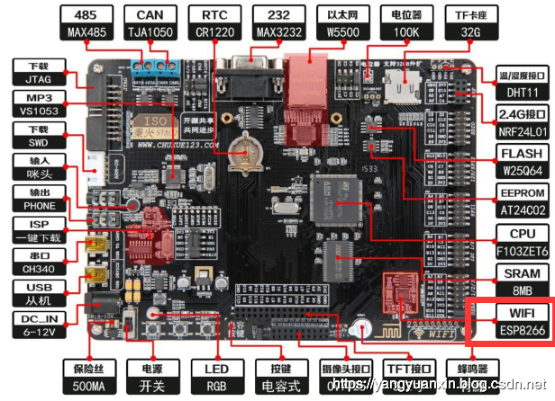
I had some losses before running this experiment. Let me come together!
1. After the software was written, it was found that there was no enumeration of USB after the USB cable was inserted and connected to the computer
resolvent:
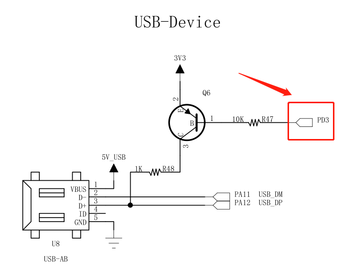
Wildfire's development board has a USB power on enabling IO, that is to say, when the PD3 is low power, the USB can work normally. If the pin is not enabled, the USB will not work naturally.
2. The problem of reading and writing SD card API version in HAL Library
resolvent:
I used the HAL Library of 1.8.0. There are significant changes in API between this library and the old version of HAL library. The parameters of the interface are not the same, and the meaning is different.
Interface of reading and writing SD card in old HAL Library
Let's look at the read-write API of the old version of HAL Library:
/**
  * @brief  Reads block(s) from a specified address in a card. The Data transfer
  *         is managed by polling mode.
  * @param  hsd: SD handle
  * @param  pReadBuffer: pointer to the buffer that will contain the received data
  * @param  ReadAddr: Address from where data is to be read
  * @param  BlockSize: SD card Data block size (in bytes)
  *          This parameter should be 512
  * @param  NumberOfBlocks: Number of SD blocks to read
  * @retval SD Card error state
  */
HAL_SD_ErrorTypedef HAL_SD_ReadBlocks(SD_HandleTypeDef *hsd, uint32_t *pReadBuffer, uint64_t ReadAddr, uint32_t BlockSize, uint32_t NumberOfBlocks)
We can see that the BlockSize here is read in bytes, and the minimum should be 512. Because the size of a block of SD card is 512, NumberOfBlocks means the number of blocks. If you read a block, it means BlockSize512. If you read N blocks, it means BlockSize512*N.
Let's look at the SD card interface of the old HAL library
/**
  * @brief  Allows to write block(s) to a specified address in a card. The Data
  *         transfer is managed by polling mode.
  * @param  hsd: SD handle
  * @param  pWriteBuffer: pointer to the buffer that will contain the data to transmit
  * @param  WriteAddr: Address from where data is to be written
  * @param  BlockSize: SD card Data block size (in bytes)
  *          This parameter should be 512.
  * @param  NumberOfBlocks: Number of SD blocks to write
  * @retval SD Card error state
  */
HAL_SD_ErrorTypedef HAL_SD_WriteBlocks(SD_HandleTypeDef *hsd, uint32_t *pWriteBuffer, uint64_t WriteAddr, uint32_t BlockSize, uint32_t NumberOfBlocks)
The same is true for writing. The BlockSize here is read in bytes, and the minimum should be 512. Because the size of a block of SD card is 512, NumberOfBlocks means the number of blocks. For writing a block, it is BlockSize512. For writing N blocks, it is BlockSize512*N.
Interface of reading and writing SD card in HAL Library of new version
However, in the latest HAL library, it is unnecessary to multiply 512. Let's take a look at the description of these two functions in HAL library version 1.8.0:
/**
  * @brief  Reads block(s) from a specified address in a card. The Data transfer
  *         is managed by polling mode.
  * @note   This API should be followed by a check on the card state through
  *         HAL_SD_GetCardState().
  * @param  hsd: Pointer to SD handle
  * @param  pData: pointer to the buffer that will contain the received data
  * @param  BlockAdd: Block Address from where data is to be read
  * @param  NumberOfBlocks: Number of SD blocks to read
  * @param  Timeout: Specify timeout value
  * @retval HAL status
  */
HAL_StatusTypeDef HAL_SD_ReadBlocks(SD_HandleTypeDef *hsd, uint8_t *pData, uint32_t BlockAdd, uint32_t NumberOfBlocks, uint32_t Timeout)
Let's take a look at the interface for reading SD card. The incoming BlockAdd here is the starting address of the block. NumberOfBlocks represents the number of blocks, so it is originally read in blocks, so it is unnecessary to multiply 512.
/**
  * @brief  Allows to write block(s) to a specified address in a card. The Data
  *         transfer is managed by polling mode.
  * @note   This API should be followed by a check on the card state through
  *         HAL_SD_GetCardState().
  * @param  hsd: Pointer to SD handle
  * @param  pData: pointer to the buffer that will contain the data to transmit
  * @param  BlockAdd: Block Address where data will be written
  * @param  NumberOfBlocks: Number of SD blocks to write
  * @param  Timeout: Specify timeout value
  * @retval HAL status
  */
HAL_StatusTypeDef HAL_SD_WriteBlocks(SD_HandleTypeDef *hsd, uint8_t *pData, uint32_t BlockAdd, uint32_t NumberOfBlocks, uint32_t Timeout)
The interface for writing SD card is also the same. Here, the incoming BlockAdd is the starting address of the block. NumberOfBlocks represents the number of blocks, so it is originally written in blocks, so there is no need to multiply 512.
Therefore, when implementing the USB mass storage device interface, I should do the following:
/**
  * @brief  .
  * @param  lun: .
  * @retval USBD_OK if all operations are OK else USBD_FAIL
  */
int8_t STORAGE_Read_FS(uint8_t lun, uint8_t *buf, uint32_t blk_addr, uint16_t blk_len)
{
  /* USER CODE BEGIN 6 */
    if(HAL_OK != HAL_SD_ReadBlocks(&hsd,(uint8_t *)buf, blk_addr , blk_len, 1000))
         return USBD_FAIL ;
    return (USBD_OK);
  /* USER CODE END 6 */
}

/**
  * @brief  .
  * @param  lun: .
  * @retval USBD_OK if all operations are OK else USBD_FAIL
  */
int8_t STORAGE_Write_FS(uint8_t lun, uint8_t *buf, uint32_t blk_addr, uint16_t blk_len)
{
  /* USER CODE BEGIN 7 */
    if(HAL_OK != HAL_SD_WriteBlocks(&hsd, (uint8_t *)buf, blk_addr , blk_len, 1000))
        return USBD_FAIL ;
    return (USBD_OK);
  /* USER CODE END 7 */
}
OK, these two problems have been solved. Let's see what we do.
1, USB enable pin configuration
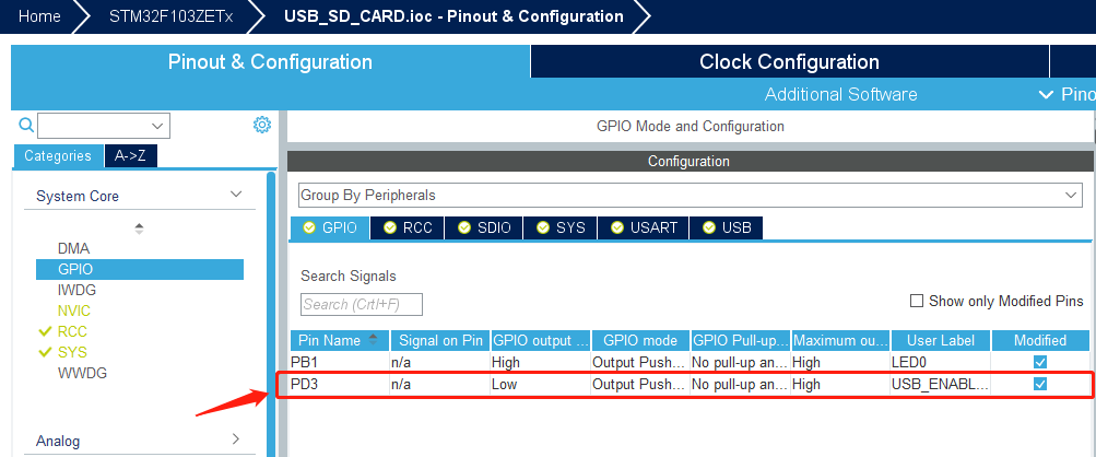
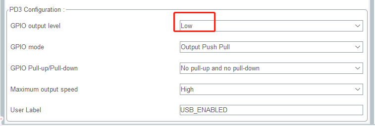
PD3 pin, the default output level is low, that is to say, D + pin is enabled, and USB is powered on.
PB1 is the lamp I used for debugging.
2, RCC clock
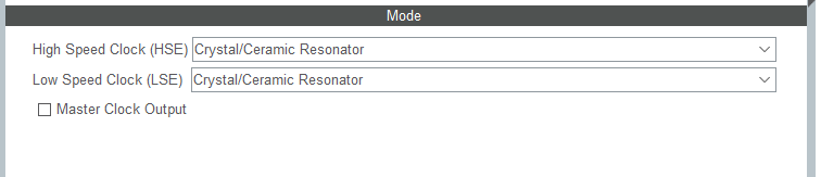
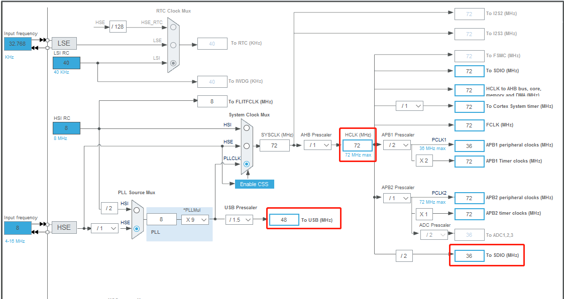
Remember a bit here, because we use USB here. The USB clock should be configured as 48MHz. See the manual for details.
SDIO is the clock is the second frequency of HCLK.
3, Debug interface
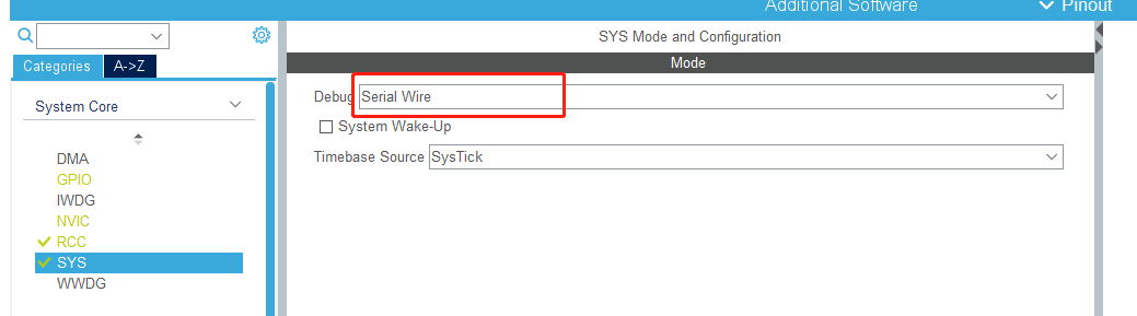
Select serial debugging here.
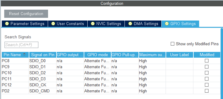
4, SDIO configuration
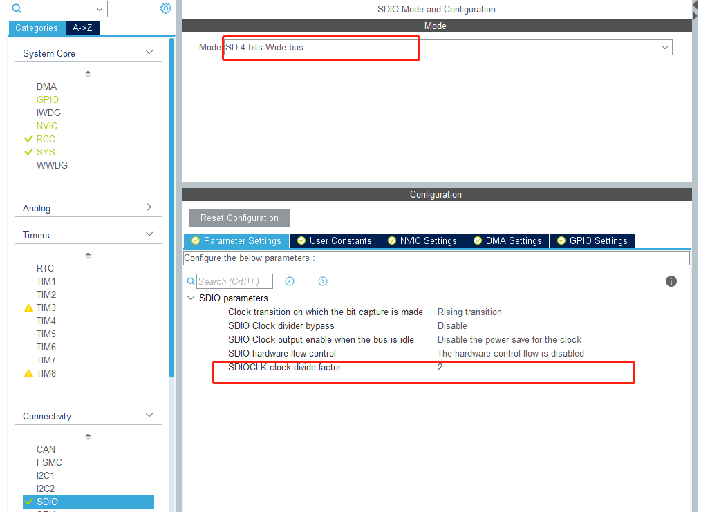
Here, we configure the mode as the SD card mode of 4-bit wide bus. As we have known before in step 2, the clock frequency of SDIO is the dichotomy of HCLK, so we set the option of SDIOCLK clock divide factor to 2.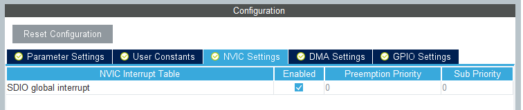
Turn on SDIO global interrupt.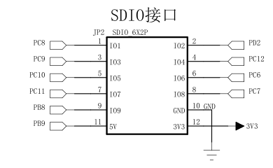
5, USB configuration
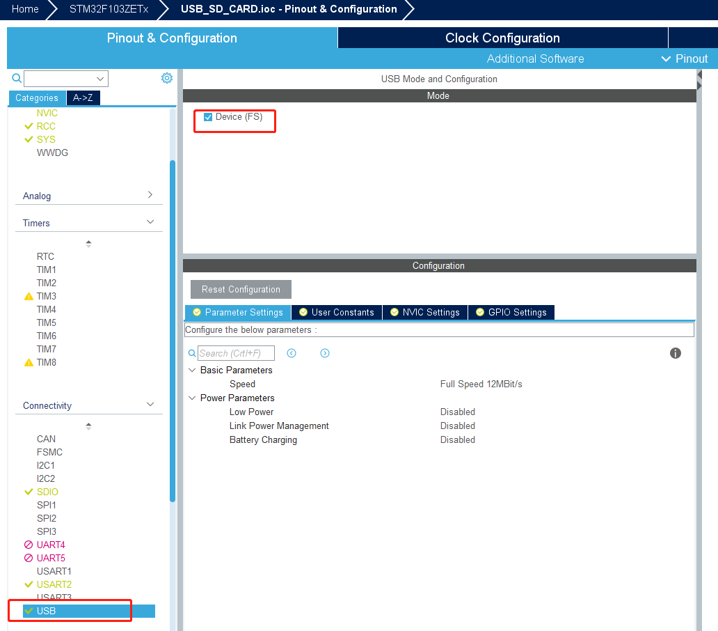
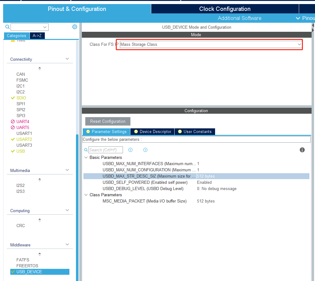
Here, the USB device is configured as mass storage, and the rest can be defaulted.
6, Generate and add code logic
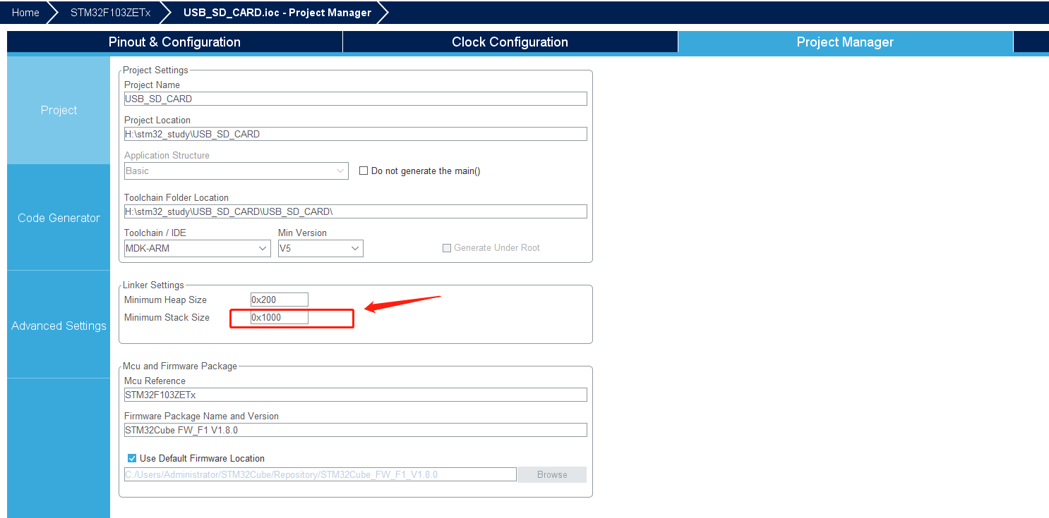
Here we'll make the stack a little larger so that we can test it later in the code.
The following interfaces are implemented in usbd storage if. C:
Storage? Getcapacity? Fs to obtain the capacity information of the U SB flash disk
 Storage? Isready? Fs to get the status of the U SB flash disk
 Storage read FS
 Storage write FS
Get how many blocks there are and the size of the blocks through the interface.
/**
  * @brief  .
  * @param  lun: .
  * @param  block_num: .
  * @param  block_size: .
  * @retval USBD_OK if all operations are OK else USBD_FAIL
  */
int8_t STORAGE_GetCapacity_FS(uint8_t lun, uint32_t *block_num, uint16_t *block_size)
{
  /* USER CODE BEGIN 3 */
    *block_num  = hsd.SdCard.BlockNbr ;
    *block_size = hsd.SdCard.BlockSize ;
    return (USBD_OK);
  /* USER CODE END 3 */
}
Judge whether the status of SD card is ready. The description of the status is as follows:
typedef enum
{
  HAL_SD_STATE_RESET                  = ((uint32_t)0x00000000U),  /*!< SD not yet initialized or disabled  */
  HAL_SD_STATE_READY                  = ((uint32_t)0x00000001U),  /*!< SD initialized and ready for use    */
  HAL_SD_STATE_TIMEOUT                = ((uint32_t)0x00000002U),  /*!< SD Timeout state                    */
  HAL_SD_STATE_BUSY                   = ((uint32_t)0x00000003U),  /*!< SD process ongoing                  */
  HAL_SD_STATE_PROGRAMMING            = ((uint32_t)0x00000004U),  /*!< SD Programming State                */
  HAL_SD_STATE_RECEIVING              = ((uint32_t)0x00000005U),  /*!< SD Receiving State                  */
  HAL_SD_STATE_TRANSFER               = ((uint32_t)0x00000006U),  /*!< SD Transfert State                  */
  HAL_SD_STATE_ERROR                  = ((uint32_t)0x0000000FU)   /*!< SD is in error state                */
}HAL_SD_StateTypeDef;
/**
  * @brief  .
  * @param  lun: .
  * @retval USBD_OK if all operations are OK else USBD_FAIL
  */
int8_t STORAGE_IsReady_FS(uint8_t lun)
{
  /* USER CODE BEGIN 4 */
    uint8_t state = 0;
    state = HAL_SD_GetState(&hsd) ;
    if(HAL_SD_STATE_READY != state)
        return USBD_FAIL ;
    return (USBD_OK);
  /* USER CODE END 4 */
}
USB read and write SD card
/**
  * @brief  .
  * @param  lun: .
  * @retval USBD_OK if all operations are OK else USBD_FAIL
  */
int8_t STORAGE_Read_FS(uint8_t lun, uint8_t *buf, uint32_t blk_addr, uint16_t blk_len)
{
  /* USER CODE BEGIN 6 */
    if(HAL_OK != HAL_SD_ReadBlocks(&hsd,(uint8_t *)buf, blk_addr , blk_len, 1000))
         return USBD_FAIL ;
    return (USBD_OK);
  /* USER CODE END 6 */
}

/**
  * @brief  .
  * @param  lun: .
  * @retval USBD_OK if all operations are OK else USBD_FAIL
  */
int8_t STORAGE_Write_FS(uint8_t lun, uint8_t *buf, uint32_t blk_addr, uint16_t blk_len)
{
  /* USER CODE BEGIN 7 */
    if(HAL_OK != HAL_SD_WriteBlocks(&hsd, (uint8_t *)buf, blk_addr , blk_len, 1000))
        return USBD_FAIL ;
    return (USBD_OK);
  /* USER CODE END 7 */
}
Add a debug blinker to the while loop of the main function.
/**
  * @brief  The application entry point.
  * @retval int
  */
int main(void)
{
  /* USER CODE BEGIN 1 */
  /* USER CODE END 1 */


  /* MCU Configuration--------------------------------------------------------*/

  /* Reset of all peripherals, Initializes the Flash interface and the Systick. */
  HAL_Init();

  /* USER CODE BEGIN Init */

  /* USER CODE END Init */

  /* Configure the system clock */
  SystemClock_Config();

  /* USER CODE BEGIN SysInit */

  /* USER CODE END SysInit */

  /* Initialize all configured peripherals */
  MX_GPIO_Init();
  MX_SDIO_SD_Init();
  MX_USART2_UART_Init();
  MX_USB_DEVICE_Init();
  /* USER CODE BEGIN 2 */

  /* USER CODE END 2 */


  /* Infinite loop */
  /* USER CODE BEGIN WHILE */
    while (1)
    {
    /* USER CODE END WHILE */

    /* USER CODE BEGIN 3 */
        //LED debugging light turns over at a frequency of 500ms
        HAL_GPIO_TogglePin(LED0_GPIO_Port,LED0_Pin);
         HAL_Delay(1000);
    }

  /* USER CODE END 3 */
}
7, Operation results
Insert the USB cable into the interface of USB DEVICE and connect it to the USB port of PC, and eject the removable disk at PC, the experiment is successful.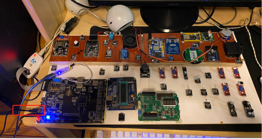
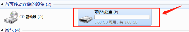
I use a 4GB memory card and the PC displays 3.68GB. Why? Du Niang:
Kingston 4G SD card only has 3.68G?
Your computer's algorithm is 1024MB=1GB
The algorithm of U disk manufacturer is 1000MB=1GB
In addition, the product error allowed by law will be added. Generally, the manufacturer will take the minimum value and will not give you more space.
Why is 4G mobile memory card only 3.68G in the mobile phone?
Hardware manufacturers use decimal system for calculation convenience, that is, 1K for full 1000 bytes, 1M for full 1000K, and so on.
In the software design, because the computer is binary, it is 1K when it is full of 1024 bytes, i.e. 2 to the 10th power, and 1M when it is 1024K.
So the bigger your card is, the bigger the gap will be, which will be more obvious on the hard disk.

