Abstract: this blog introduces a method that STM32 uses a timer channel to control any IO to output the same PWM wave. The hardware platform used in this paper is STM32F407VET6. The codes of other types of platforms may be different, but the principles are general.
Implementation principle: we all know that STM32 can directly output PWM wave from hardware by using timer channel. A timer has four channels, of which each channel of advanced timer has two positive and negative output control ports, that is, a timer can output up to 8 channels of PWM wave from hardware at the same time (for advanced timer, see the specific timer structure block diagram for others), Although this has been a lot, I think it is not enough, and the most important thing is that these hardware PWM wave output IO ports are fixed by hardware, and the degree of freedom in control is not high enough, so I have this blog and the following code. Cough, back to the implementation principle, because a timer channel realizes the output duty cycle adjustable PWM wave from the hardware, using the CNT counter and the capture / comparison register (this is not clear. Take a good look at the timer block diagram in the reference manual). When the CNT counter counts to the set value of automatic reassembly, it will start counting again, The capture / comparison register will automatically flip the level from the hardware when the CNT counts to the set value. This blog makes use of this point, because in fact, when the hardware outputs the PWM wave for level reversal, the corresponding interrupt will be generated (if the corresponding interrupt is enabled). Then as long as the level reversal is carried out in the interrupt service function, the effect of controlling any IO to output the same PWM wave can be realized (of course, in order to prevent the timer channel from outputting PWM wave to the corresponding IO port on the hardware, it is necessary to prohibit the timer channel from outputting PWM wave to the bound hardware IO port.).
This blog takes the use of channel 1 of TIM1 to control any IO to output the same PWM wave as an example. Before officially displaying the code, I would like to thank anfulai for its help in learning embedded. Its good code style also deeply affects me, and the next code is largely changed on the basis of anfulai's relevant source code.
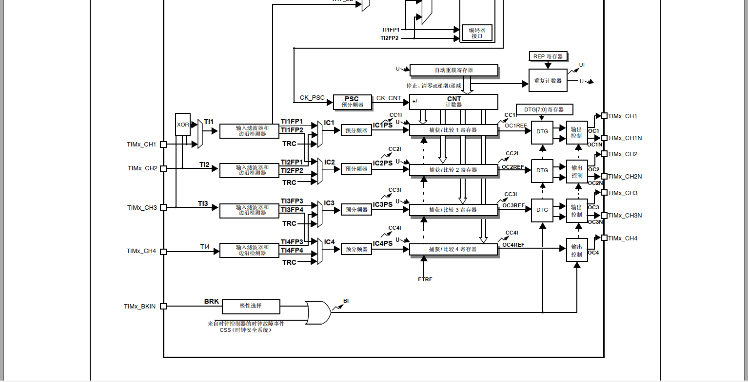
The structure block diagram of advanced timers TIM1 and TIM8 is as follows
The TIM timer configuration function code is as follows. In actual use, if you want to realize the functions shown in this blog, please use the timer with capture / comparison register on the hardware for the incoming TIMx parameter
/*
*********************************************************************************************************
*	Function name: bsp_SetTIM_CC_ForInt
*	Function Description: configure TIM, NVIC and CCR, which can be used for simple timing interrupt, and configure the capture comparison interrupt of the specified channel to achieve the effect of PWM (in fact, PWM will not be output directly to the pin,
                    To put it bluntly, by using this function, combined with bsp_TIM_PWM_ChangePulse function and interrupt service function, a timer channel can control any IO to output any PWM). The interrupt service program is implemented by the application program.
*	Formal parameter: TIMx: timer
*			  _ucChannel : Channels 1 ~ 4.
*			  _ulFreq : Timing frequency (Hz). 0 means off.
*			  _usPeriod : The actual value of automatic reassembly should be the number of times minus one.
*			  _PreemptionPriority : Interrupt priority grouping
*			  _SubPriority : Sub priority
*	Return value: None
*********************************************************************************************************
*/
void bsp_SetTIM_CC_ForInt(TIM_TypeDef* TIMx, uint8_t _ucChannel, uint32_t _ulFreq, uint16_t  _usPeriod, uint8_t _PreemptionPriority, uint8_t _SubPriority)
{
	TIM_TimeBaseInitTypeDef  TIM_TimeBaseStructure;
    TIM_OCInitTypeDef  TIM_OCInitStructure;
	uint16_t usPeriod;
	uint16_t usPrescaler;
	uint32_t uiTIMxCLK;

  	/* Enable TIM clock */
	if ((TIMx == TIM1) || (TIMx == TIM8) || (TIMx == TIM9) || (TIMx == TIM10) || (TIMx == TIM11))
	{
		RCC_APB2PeriphClockCmd(bsp_GetRCCofTIM(TIMx), ENABLE);
	}
	else
	{
		RCC_APB1PeriphClockCmd(bsp_GetRCCofTIM(TIMx), ENABLE);
	}

	if (_ulFreq == 0)
	{
		TIM_Cmd(TIMx, DISABLE);		/* Turn off timing output */
		return;
	}

    /*-----------------------------------------------------------------------
		system_stm32f4xx.c The clock configuration of void SetSysClock(void) function in the file is as follows:

		HCLK = SYSCLK / 1     (AHB1Periph)
		PCLK2 = HCLK / 2      (APB2Periph)
		PCLK1 = HCLK / 4      (APB1Periph)

		Because APB1 prescaler! = 1, timxclk on APB1 = pclk1 x 2 = systemcorelock / 2;
		Because APB2 prescaler! = 1, timxclk = pclk2 x 2 = systemcorelock on APB2;

		APB1 Timers include TIM2, tim3, TIM4, tim5, tim6, tim7, tim12, tim13 and tim14
		APB2 Timers include TIM1, tim8, TIM9, TIM10 and tim11

	----------------------------------------------------------------------- */
	if ((TIMx == TIM1) || (TIMx == TIM8) || (TIMx == TIM9) || (TIMx == TIM10) || (TIMx == TIM11))
	{
		/* APB2 timer */
		uiTIMxCLK = SystemCoreClock;
	}
	else	/* APB1 timer */
	{
		uiTIMxCLK = SystemCoreClock / 2;
	}

    usPrescaler =  (uiTIMxCLK / _ulFreq) / (_usPeriod + 1) - 1;		/* division factor  */

	/* Time base configuration */
	TIM_TimeBaseStructure.TIM_Period = usPeriod;
	TIM_TimeBaseStructure.TIM_Prescaler = usPrescaler;
	TIM_TimeBaseStructure.TIM_ClockDivision = 0;
	TIM_TimeBaseStructure.TIM_CounterMode = TIM_CounterMode_Up;

	TIM_TimeBaseInit(TIMx, &TIM_TimeBaseStructure);

    /*PWM Mode configuration*/
    TIM_OCInitStructure.TIM_OCMode = TIM_OCMode_PWM1;//When it is configured as PWM mode 1, the high level is output first, and then the level is changed when the comparison value is reached
    TIM_OCInitStructure.TIM_OutputState = TIM_OutputState_Disable;//Main output disabled
    TIM_OCInitStructure.TIM_OutputNState = TIM_OutputNState_Disable;//Complementary Output Disable
    TIM_OCInitStructure.TIM_Pulse = 0;//Set duty cycle size
    TIM_OCInitStructure.TIM_OCPolarity = TIM_OCPolarity_High;//The main output RMS is high

	if (_ucChannel == 1)
	{
		TIM_OC1Init(TIMx, &TIM_OCInitStructure);
//		TIM_OC1PreloadConfig(TIMx, TIM_OCPreload_Enable);
        /* TIM Interrupts enable */
        TIM_ITConfig(TIMx, TIM_IT_CC1, ENABLE);
	}
	else if (_ucChannel == 2)
	{
		TIM_OC2Init(TIMx, &TIM_OCInitStructure);
//		TIM_OC2PreloadConfig(TIMx, TIM_OCPreload_Enable);
        /* TIM Interrupts enable */
        TIM_ITConfig(TIMx, TIM_IT_CC2, ENABLE);
	}
	else if (_ucChannel == 3)
	{
		TIM_OC3Init(TIMx, &TIM_OCInitStructure);
//		TIM_OC3PreloadConfig(TIMx, TIM_OCPreload_Enable);
        TIM_ITConfig(TIMx, TIM_IT_CC3, ENABLE);
	}
	else if (_ucChannel == 4)
	{
		TIM_OC4Init(TIMx, &TIM_OCInitStructure);
//		TIM_OC4PreloadConfig(TIMx, TIM_OCPreload_Enable);
        TIM_ITConfig(TIMx, TIM_IT_CC4, ENABLE);
	}

	/* TIM Interrupts enable */
	TIM_ITConfig(TIMx, TIM_IT_Update, ENABLE);

	TIM_ARRPreloadConfig(TIMx, ENABLE);

	/* TIMx enable counter */
	TIM_Cmd(TIMx, ENABLE);

	/* Configure TIM scheduled updates and capture / compare interrupts (Updates) */
	{
		NVIC_InitTypeDef NVIC_InitStructure;	/* Interrupt structures are defined in misc.h */
		uint8_t irq = 0;	/* Interrupt number, defined in stm32f4xx.h */

		NVIC_InitStructure.NVIC_IRQChannelPreemptionPriority = _PreemptionPriority;
		NVIC_InitStructure.NVIC_IRQChannelSubPriority = _SubPriority;
		NVIC_InitStructure.NVIC_IRQChannelCmd = ENABLE;

		if ((TIMx == TIM1) || (TIMx == TIM10))
			irq = TIM1_UP_TIM10_IRQn;
		else if (TIMx == TIM2)
			irq = TIM2_IRQn;
		else if (TIMx == TIM3)
			irq = TIM3_IRQn;
		else if (TIMx == TIM4)
			irq = TIM4_IRQn;
		else if (TIMx == TIM5)
			irq = TIM5_IRQn;
		else if (TIMx == TIM6)
			irq = TIM6_DAC_IRQn;
		else if (TIMx == TIM7)
			irq = TIM7_IRQn;
		else if ((TIMx == TIM8) || (TIMx == TIM13))
			irq = TIM8_UP_TIM13_IRQn;
		else if (TIMx == TIM9)
			irq = TIM1_BRK_TIM9_IRQn;
		else if (TIMx == TIM11)
			irq = TIM1_TRG_COM_TIM11_IRQn;
		else if (TIMx == TIM12)
			irq = TIM8_BRK_TIM12_IRQn;
		else if (TIMx == TIM14)
			irq = TIM8_TRG_COM_TIM14_IRQn;

        NVIC_InitStructure.NVIC_IRQChannel = irq;
        NVIC_Init(&NVIC_InitStructure);

        /* For advanced timers TIM1 and tim8, the capture / compare interrupt function needs to be configured separately  */
        if (TIMx == TIM1) {
            irq = TIM1_CC_IRQn;
            NVIC_InitStructure.NVIC_IRQChannel = irq;
            NVIC_Init(&NVIC_InitStructure);
        }
        else if (TIMx == TIM8) {
            irq = TIM8_CC_IRQn;
            NVIC_InitStructure.NVIC_IRQChannel = irq;
            NVIC_Init(&NVIC_InitStructure);
        }
	}
}
Add the functions that the above code depends on
/*
*********************************************************************************************************
*	Function name: bsp_GetRCCofTIM
*	Function Description: get RCC register according to TIM
*	Formal parameters: None
*	Return value: TIM peripheral clock name
*********************************************************************************************************
*/
uint32_t bsp_GetRCCofTIM(TIM_TypeDef* TIMx)
{
	uint32_t rcc = 0;

	/*
		APB1 Timers include TIM2, tim3, TIM4, tim5, tim6, tim7, tim12, tim13 and tim14
		APB2 Timers include TIM1, tim8, TIM9, TIM10 and tim11
	*/
	if (TIMx == TIM1)
	{
		rcc = RCC_APB2Periph_TIM1;
	}
	else if (TIMx == TIM8)
	{
		rcc = RCC_APB2Periph_TIM8;
	}
	else if (TIMx == TIM9)
	{
		rcc = RCC_APB2Periph_TIM9;
	}
	else if (TIMx == TIM10)
	{
		rcc = RCC_APB2Periph_TIM10;
	}
	else if (TIMx == TIM11)
	{
		rcc = RCC_APB2Periph_TIM11;
	}
	/* Here is the APB1 clock */
	else if (TIMx == TIM2)
	{
		rcc = RCC_APB1Periph_TIM2;
	}
	else if (TIMx == TIM3)
	{
		rcc = RCC_APB1Periph_TIM3;
	}
	else if (TIMx == TIM4)
	{
		rcc = RCC_APB1Periph_TIM4;
	}
	else if (TIMx == TIM5)
	{
		rcc = RCC_APB1Periph_TIM5;
	}
	else if (TIMx == TIM6)
	{
		rcc = RCC_APB1Periph_TIM6;
	}
	else if (TIMx == TIM7)
	{
		rcc = RCC_APB1Periph_TIM7;
	}
	else if (TIMx == TIM12)
	{
		rcc = RCC_APB1Periph_TIM12;
	}
	else if (TIMx == TIM13)
	{
		rcc = RCC_APB1Periph_TIM13;
	}
	else if (TIMx == TIM14)
	{
		rcc = RCC_APB1Periph_TIM14;
	}

	return rcc;
}
The function of adjusting the duty cycle is shown below
/**
 * @brief  Time to change PWM output high level (duty cycle)
 * @param  Time of high level of timer, channel and output PWM (not real time, but CNT value corresponding to level reversal)
 * @retval   nothing
 */
void bsp_TIM_PWM_ChangePulse(TIM_TypeDef* TIMx, uint8_t _ucChannel, uint16_t _usPulse)
{
	if (_ucChannel == 1) {
        TIM_SetCompare1(TIMx, _usPulse);
	}
	else if (_ucChannel == 2) {
        TIM_SetCompare2(TIMx, _usPulse);
	}
	else if (_ucChannel == 3) {
        TIM_SetCompare3(TIMx, _usPulse);
	}
	else if (_ucChannel == 4) {
        TIM_SetCompare4(TIMx, _usPulse);
	}
}
The interrupt service function is as follows, because this blog takes channel 1 of TIM1 on STM32F407VET6 platform as an example. If you need to use other models of platforms and timer channels, change to the corresponding interrupt service function
/**
 * @brief  TIM1 Timed interrupt service routine
 * @param  nothing
 * @retval   nothing
 */
void TIM1_UP_TIM10_IRQHandler(void)
{
    if(TIM_GetITStatus(TIM1, TIM_IT_Update) != RESET) {
        /* Clear flag */
        TIM_ClearITPendingBit(TIM1, TIM_IT_Update);

        /* User program */
		//The specified IO output high level can be set here
    }
}

void TIM1_CC_IRQHandler(void)
{
    if(TIM_GetITStatus(TIM1, TIM_IT_CC1) != RESET) {
        /* Clear flag */
        TIM_ClearITPendingBit(TIM1, TIM_IT_CC1);

        /* User program */
		//The specified IO output low level can be set here
    }
}
Practical Demo example
int main(void)
{
	bsp_SetTIM_CC_ForInt(TIM1, 1, 1000, 1999, 2, 0);	/* Configure channel 1 of TIM1, the timing interrupt frequency is 1kHz, the counted reload value is 1999, the interrupt priority group is 2, and the sub priority is 0 */
	for(;;) {
		bsp_TIM_PWM_ChangePulse(TIM1, 1, 999)	/* Change the duty cycle to 50% */
		DelayMs(1000);
		bsp_TIM_PWM_ChangePulse(TIM1, 1, 199)	/* Change the duty cycle to 10% */
		DelayMs(1000);
		/* The IO port for outputting PWM wave is determined by the user program in the interrupt service function */
	}
}