Because the single chip microcomputer can not directly drive the motor, it is necessary to add a motor drive module between them. The L298N motor drive module was used in the previous article. Now we recommend a new motor drive module. It is much easier to use than L298N, and it takes up a small volume and has less heat. TB6612 can drive two DC motors at a time, and the output PWM is also very simple. The following is an introduction to TB6612 motor through experiments.
1, TB6612 motor drive module
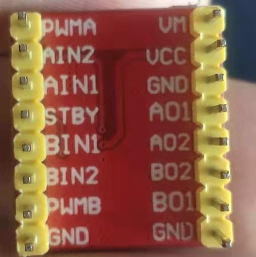
First introduce the pin function of TB6612 motor drive module. VM: the maximum power supply is 15V. I generally use 12V DC power supply. VCC adopts 3.3V or 5V power supply. The GND on the board is grounded. Try to connect all three GNDS, and try to connect the GND of the power supply and the GND pin of STM32 at the same time. STBY: enable port, add 3.3V or 5V voltage. AIN1, AIN2, BIN1, BIN2: MCU input to the drive module. AO1, AO2, BO1, BO2: input of drive module to motor. PWMA and PWMB: output PWM to ports A and B, and adjust the motor speed through PWM.
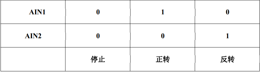
The forward and reverse rotation of the motor can be controlled by changing the input voltage, as shown in the following figure:
The simplest motor experiment is carried out by using the reduced speed DC motor with encoder: the wiring is shown in the figure below:
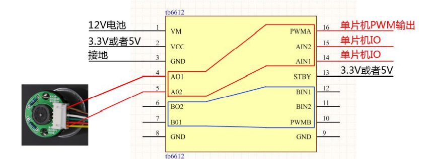
VCC and GND are directly used to drive the motor. AIN1 is connected to VCC, AIN2 is connected to GND, PWMA is connected to VCC and STBY is connected to VCC, which means that the motor rotates at full speed in one direction. If the motor rotates normally, there is no problem with each module. The next experiment can be carried out. Using GPIO to control the forward and reverse rotation of the motor is to define two independent GPIO pins, both of which are output modes. If the output of one port is high and the output of the other port is low, the motor can be reversed according to the information of GPIO. The experiment is simple and there is no code.
The motor can be forward and reverse, so how to control the rotation speed of the motor? PWM is used here. Just now, PWMA is connected to VCC, which means PWMA is always at high level. Next, an IO port is defined as PWM function, and the motor speed is adjusted by changing the duty cycle. The following is the PWM configuration code, after which we only need to call TIM_SetCompare1(TIM8,20); This function is used to change the duty cycle, so as to achieve the function of speed regulation. Connect the output PWM pin to the PWMA port of the drive module, and then the motor can rotate according to the set PWM.
void TIM1_PWM_Init(u16 arr,u16 psc)
{
	 GPIO_InitTypeDef GPIO_InitStructure;
	TIM_TimeBaseInitTypeDef  TIM_TimeBaseStructure;
	TIM_OCInitTypeDef  TIM_OCInitStructure;

	//Enable GPIO peripheral clock enable
	RCC_APB2PeriphClockCmd(RCC_APB2Periph_TIM8, ENABLE);
 	RCC_APB2PeriphClockCmd(RCC_APB2Periph_GPIOC , ENABLE);


  //Set this pin as the multiplexing output function to output the PWM pulse waveform of TIM1 CH1
	GPIO_InitStructure.GPIO_Pin = GPIO_Pin_6; //TIM_CH1
	GPIO_InitStructure.GPIO_Mode = GPIO_Mode_AF_PP;  //Multiplexed push-pull output
	GPIO_InitStructure.GPIO_Speed = GPIO_Speed_50MHz;
	GPIO_Init(GPIOC, &GPIO_InitStructure);

	//Initialization timer ARR,PSC
	TIM_TimeBaseStructure.TIM_Period = arr; //Sets the value of the auto reload register cycle of the load activity at the next update event 	  80K
	TIM_TimeBaseStructure.TIM_Prescaler =psc; //Set the prescaled value used as the divisor of TIMx clock frequency without frequency division
	TIM_TimeBaseStructure.TIM_ClockDivision = 0; //Set clock division: TDTS = Tck_tim
	TIM_TimeBaseStructure.TIM_CounterMode = TIM_CounterMode_Up;  //TIM up count mode
	TIM_TimeBaseInit(TIM8, &TIM_TimeBaseStructure); //According to Tim_ The parameter specified in timebaseinitstruct initializes the time base unit of TIMx

  //Initialize output comparison parameters
	TIM_OCInitStructure.TIM_OCMode = TIM_OCMode_PWM2; //Select timer mode: TIM pulse width modulation mode 2
	TIM_OCInitStructure.TIM_OutputState = TIM_OutputState_Enable; //Compare output enable
	TIM_OCInitStructure.TIM_Pulse = 0; //Set the pulse value to be loaded into the capture comparison register
	TIM_OCInitStructure.TIM_OCPolarity = TIM_OCPolarity_High; //Output polarity: TIM output has high polarity
	TIM_OC1Init(TIM8, &TIM_OCInitStructure);  //According to Tim_ Initialize peripheral TIMx with the parameters specified in ocinitstruct

	//Enable TIM1
	TIM_Cmd(TIM8, ENABLE);  //Enable TIM1

	//MOE main output enable pwm
  TIM_CtrlPWMOutputs(TIM8,ENABLE);

	//CH1 preload enable
	TIM_OC1PreloadConfig(TIM8, TIM_OCPreload_Enable);

	//Enable TIMx preload register on ARR
	TIM_ARRPreloadConfig(TIM8, ENABLE);
}
The motor with encoder can also be used as a closed-loop motor control system. The PID algorithm is used to control the motor. When it is controllable, it can run at a constant speed. Here, the value calculated by PID is the duty cycle to be set by PWM. The balance car will be shared when it is made later.