1, Hardware
1. Sensor: hydraulic sensor, 12vDC, RS485 data output, Modbus protocol communication
2. Circuit: according to the sensor properties, the circuit is mainly composed of two parts, communication circuit and power supply
(1) 485 circuit: because 485 is half duplex communication, it needs to control the transceiver, so it is simply designed as an automatic transceiver circuit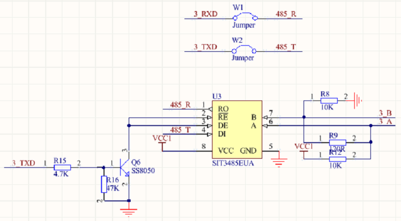
Connect jumper cap W1 and W2 to use RS485 to send and receive, not to connect is common serial port transceiver. RE and DE are transceiver enabled, 485 mode is selected: 3_ When sending data, the start bit (falling edge) of the data will be 3_ When the TXD pin level is pulled low, it will enable sending. Sensor connection 3_A,3_B.
(2) Switch circuit: mainly to control the switch of sensor to reduce power consumption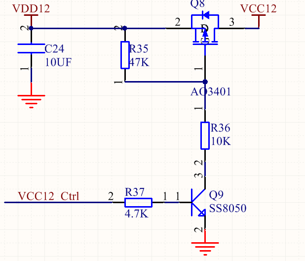
2, Test 485 circuit
1. 485 circuit test program
For single chip microcomputer, it is still serial communication, but RS232 level → RS485 level is realized through 485 chip.
(1) Initialize serial port 3, and turn on serial port to receive interrupt during initialization
void MX_USART3_UART_Init(void)
{

  huart3.Instance = USART3;
  huart3.Init.BaudRate = 9600;
  huart3.Init.WordLength = UART_WORDLENGTH_8B;
  huart3.Init.StopBits = UART_STOPBITS_1;
  huart3.Init.Parity = UART_PARITY_NONE;
  huart3.Init.Mode = UART_MODE_TX_RX;
  huart3.Init.HwFlowCtl = UART_HWCONTROL_NONE;
  huart3.Init.OverSampling = UART_OVERSAMPLING_16;
  if (HAL_UART_Init(&huart3) != HAL_OK)
  {
    Error_Handler();
  }
  Usart3RecIT();//Open serial port 3 to receive interrupt
  start_capture();//Send request frame
}
(2) Save serial data in receive interrupt callback function
void HAL_UART_RxCpltCallback(UART_HandleTypeDef *huart)
{

	if(huart->Instance == USART3){//RS485 equipment
		HAL_UART_Receive_IT(&huart3, &uart3Data, 1);
        uart3WriteByte(uart3Data);//Received data is written to the cache
		uart3DataFlg = 1;
	}
}
(3) Cache data: Ring queue, no wordiness
#define SENSOR_485_DATA_BUFFER_MAX_LENGTH  60
typedef struct {
	uint16_t   front;
	uint16_t   rear;
	uint8_t*   buffer;
	uint32_t   maxSize;
}Buffer_t;
static Buffer_t sensor485Buffer;
uint8_t  sensor485DataBuffer[SENSOR_485_DATA_BUFFER_MAX_LENGTH];//Cache array

void uart3WriteByte(uint8_t data)
{
	Buffer_Puts(&sensor485Buffer,&data,1);//Join the team
}

bool Buffer_Puts(Buffer_t* buffer, uint8_t* data, uint16_t length)
{
	if (buffer->maxSize - Buffer_Size(buffer) <= length)//The team is full
		return false;
	for (uint16_t i = 0; i<length; ++i)//The queue is not full
	{
		buffer->rear = (buffer->rear + 1) % buffer->maxSize;
		buffer->buffer[buffer->rear] = data[i];//Into the team
	}
	return true;
}
(4) This interface is to send instructions to the sensor and request sensor data. The instruction needs to view the sensor instruction definition, which belongs to the protocol part, and test it first
void start_capture(){
    uint8_t TxData[10]= "1111111111";
	HAL_UART_Transmit(&huart3,TxData,10,0xffff);
    HAL_Delay(100);
}
2. Debug in Keil, send data to MCU with serial port assistant, check array sensor485DataBuffer received, receive is OK
3. But I encountered a problem, the upper computer did not receive the "1111111" sent by 2 - (4), and the MCU sent something wrong
(1) Check that TX, R15 and R16 have signals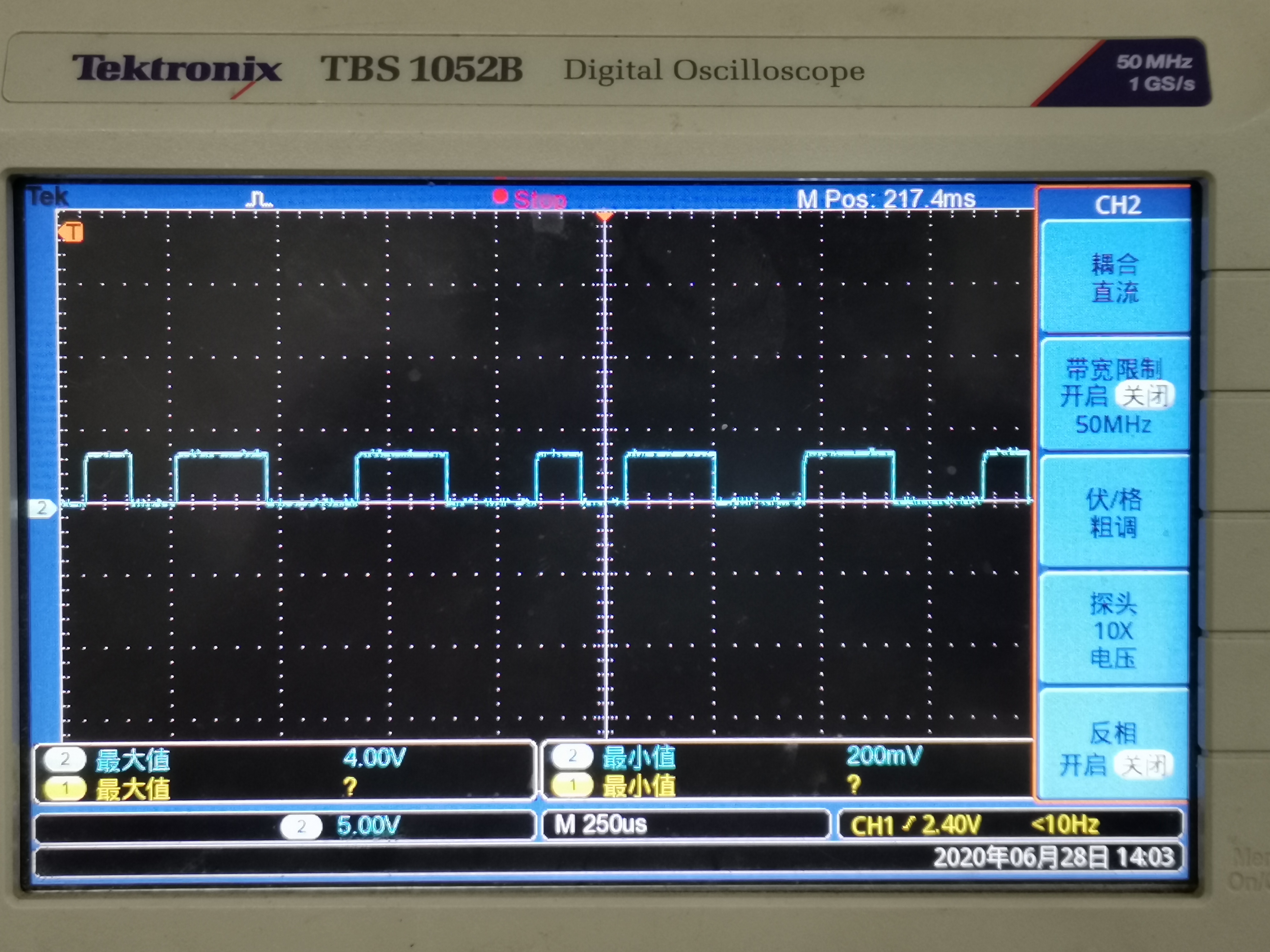
(2) The first reaction is that 485 chip failed to send enable. Check the RE and DE pins. It turns out that the transistor is always on without blocking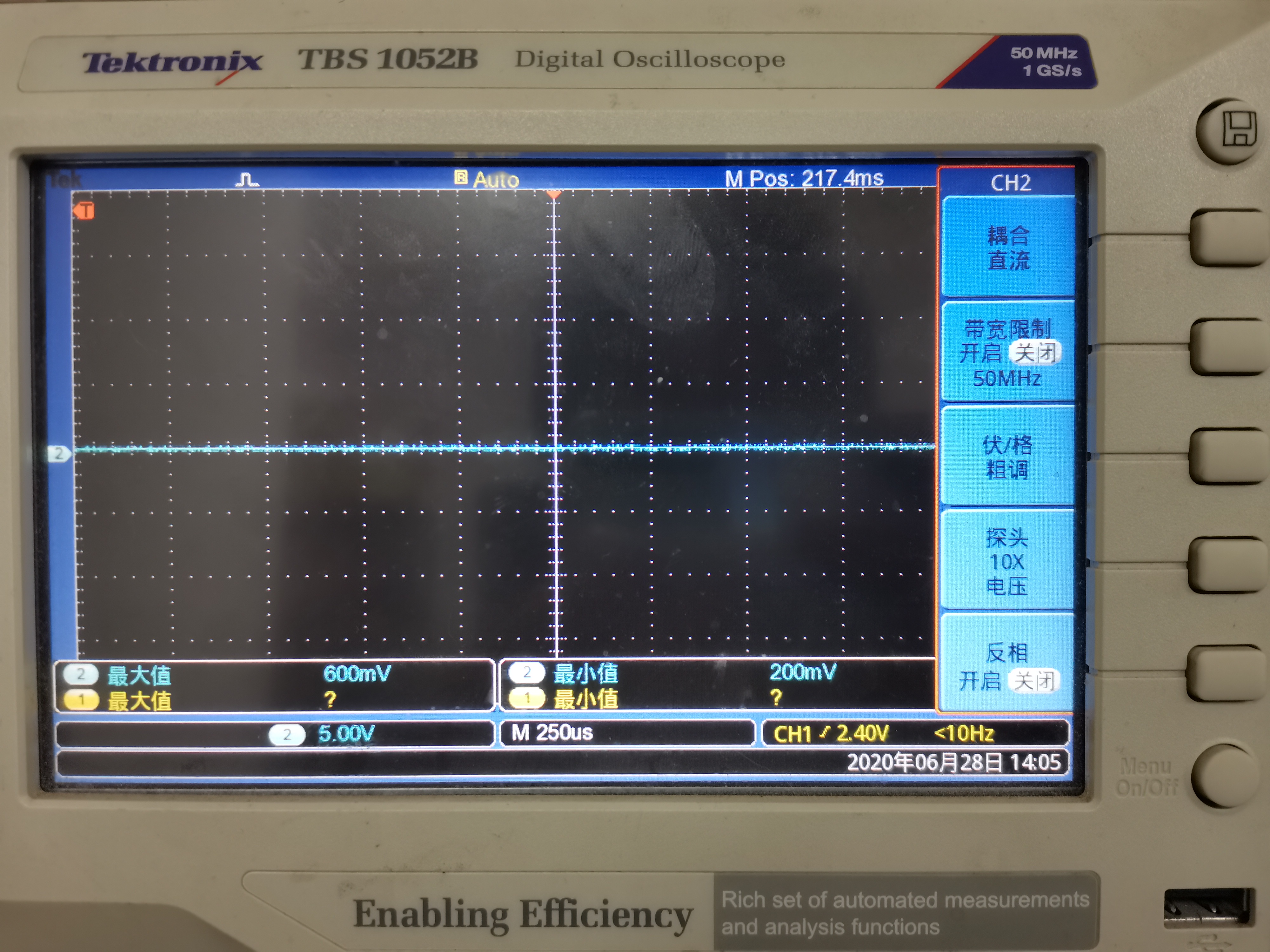
(3) Helpless, simply replaced the triode with inverter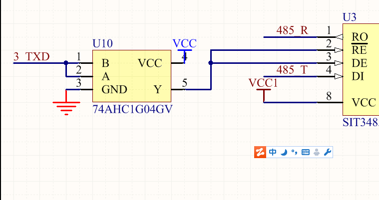
(4) Hope you can use it, and write the software quickly
3, Add Modbus Protocol
1. Protocol principle
(1) The above test instructions: link layer hardware protocol √;
(2) But the question is, can only hardware protocols communicate with sensors? Of course not. The sensor is not a computer. It doesn't have a host computer: you click send and send the data. At this time, the MCU is needed to tell it to send. So we also need: link layer software protocol Modbus protocol √;
(3) There are several aspects of Modbus programming that are helpful for us to select:
-
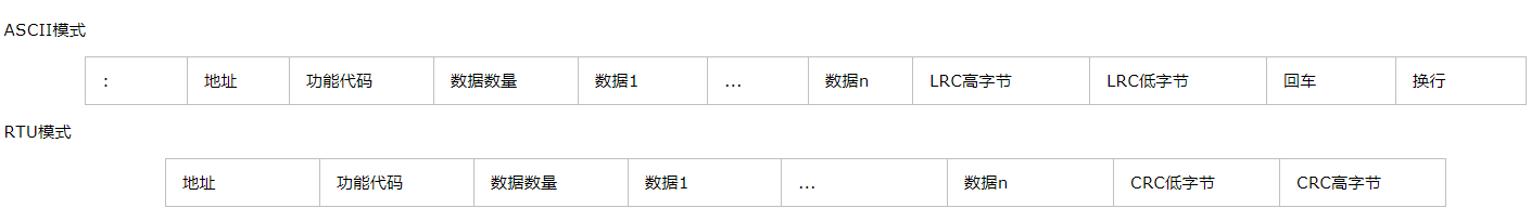
In the form of frame communication, there are two modes of ASCII and RTU. The address and function code in the frame are all one or more bytes, and each byte is an 8-bit serial port data
-
If a serial port is connected to multiple 4856 devices, different 485 devices can be distinguished by address. Of course, the serial port resources are sufficient and can be mounted on multiple serial ports
-
RTU mode distinguishes the first and the second frames of data by the time interval between two frames of data. If the data interval between serial ports is greater than 3.5 bytes, then it is considered that one frame of data is over. At 9600bps/s baud rate, the transmission time of 3.5 bytes is about 4ms; in ASCII mode, read back and line feed is OK
-
If you want to read the sensor status and data, you need to send a request frame
-
Data need CRC check
-
For specific instruction rules, please refer to the sensor instruction document
2. Programming according to sensor instruction document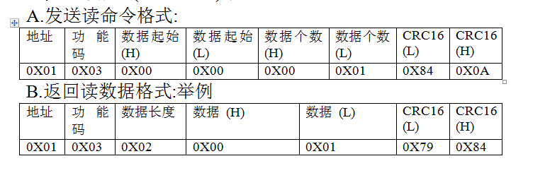
(1) Turn on the sensor switch
void open_sensor(){
	//Control power switch pin pull up
}
(2) Send read command
void start_read(){
    uint8_t TxData[10]= "010300000001840A";
	HAL_UART_Transmit(&huart3,TxData,10,0xffff);
    HAL_Delay(100);
}
(3) Read data
- When receiving data in the serial port receiving interrupt, if the next serial port data arrives within 4ms, the timer interrupt will not take effect; if not, the program will enter the timer interrupt after receiving a frame of data, which is very important
void HAL_UART_RxCpltCallback(UART_HandleTypeDef *huart)
{
		if(huart->Instance == USART3){
			  HAL_TIM_Base_Stop_IT(&htim5);
			  HAL_UART_Receive_IT(&huart3, &uart3Data, 1);
              uart3WriteByte(uart3Data);
              HAL_TIM_Base_Start_IT(&htim5);//Start timing 4ms, that is, the time interval between modbus devices transmitting a frame of data at 9600 baud rate
			  uart3DataFlg = 1;
		}
}
- Processing data in timer interrupt
void HAL_TIM_PeriodElapsedCallback(TIM_HandleTypeDef *htim)
{
  if(htim==(&htim5))
  {
		//TIM_ClearITPendingBit(TIM5,TIM_IT_Update); / / the standard library needs to clear the TIMx update interrupt flag, and the HAL library does not need to write the business logic directly
		 HAL_TIM_Base_Stop_IT(&htim5);
		 Modbus_Work();//Data processing function
		 Uart3BufClear();
		 RS485_RX_CNT++;
  }
}
(4) Data CRC check
- CRC principle is not wordy
- The polynomials of different types of CRC verification are not uniform. Here is 0xA001, which will be explained in the document
int16_t CRC_16( int8_t *vptr, int8_t len)
{
    uint16_t MODBUSCRC = 0xffff;
    uint16_t POLYNOMIAL = 0xa001;
    uint8_t i, j;

    for (i = 0; i < len; i++)
    {
        MODBUSCRC ^= vptr[i] ;
        for (j = 0; j < 8; j++)
        {
            if ((MODBUSCRC & 0x0001) != 0)
            {
                MODBUSCRC >>= 1;
                MODBUSCRC ^= POLYNOMIAL;
            }
            else
            {
                MODBUSCRC >>= 1;
            }
        }
    }
    return MODBUSCRC;
}
(5) Data analysis
int Modbus_Work(void)
{
	double depth;
	uint16_t  depth_high;
	uint16_t  depth_low;
	int len = strlen((char*)(sensor485DataBuffer+1));
	if(sensor485DataBuffer[1] == 0x01)//If the slave address is correct, the conversion is carried out
	{
		if((CRC_16((int8_t *)(sensor485DataBuffer+1),len))==0x0000){//CRC check
			depth_high = sensor485DataBuffer[3];
			depth_low = sensor485DataBuffer[4];
			depth = (double)((depth_high << 8) + depth_low)/1000;
		}
	}memset(sensor485DataBuffer,0,len+1);
	return depth;//This is the water depth
}
4, Precautions
1. RS485 communication, must be A to A, B to B, not reverse connection
2. If the acquisition line is too long, shielding wire should be considered