**
[STM32]PWM driven steering gear
thinking
1. Output pulse signal with PB5
2. Understand the principle of PWM
3. Understand the relevant settings of steering gear
4. Knock the code to correct the bug
Related hardware
STM32C8T6 Minimum system board
SG90 steering engine
Jlink
 DuPont line
Relevant knowledge
steering engine
High level time corresponds to steering gear rotation angle
t = 0.5ms ----------- turn the rudder to 0 °
t = 1.0ms ----------- rudder turning 45 °
t = 1.5ms ----------- the rudder turns to 90 °
t = 2.0ms -- rudder turning 135 °
t = 2.5ms ----------- turn the rudder to 180 °
Hardware
Orange Line: signal line
Red line: power supply, 3.3V can be connected
Brown wire: ground wire
code
file: main
#include "system.h"
#include "SysTick.h"
#include "pwm.h"
#include "../1127.h"

 int main(void)
 {
		u8 fx=1;
		NVIC_PriorityGroupConfig(NVIC_PriorityGroup_2);
		TIM3_CH2_PWM_Init(200-1,7200-1);//7200*200/0000=>0.02s=20ms
	 //0.5ms=0  ->5
	 //1.0ms=45 ->10
	 //1.5ms=90 ->15
	 //2.0ms=135->20
	 //2.5ms=180->25
	 while(1)
	{
		if(fx==1)
			{
			i+=5;
			}
			else
			{
				i-=5;
			}
			if(i>=25) fx=0;
		  if(i==5)  fx=1;

			delay(1000);
			LED=!LED;
			TIM_SetCompare2(TIM3,i);//Set duty cycle

		}

	}
file pwm.c
1. Header file and configuration timer interrupt service
#include "pwm.h"
#include "../1127.h"
u8 i =5;
void TIM3_IRQHandler(void)   //TIM3 interrupt
{
	if (TIM_GetITStatus(TIM3, TIM_IT_Update) != RESET) //Check whether the specified TIM interrupt occurs: TIM interrupt source
		{
		TIM_ClearITPendingBit(TIM3, TIM_IT_Update  );  //Clear the interrupt pending bit of TIMx: TIM interrupt source
			i++;
		}
}
2. Initialization function
void TIM3_CH2_PWM_Init(u16 per,u16 psc)
{
	TIM_TimeBaseInitTypeDef TIM_TimeBaseInitStructure;
	TIM_OCInitTypeDef TIM_OCInitStructure;
	GPIO_InitTypeDef GPIO_InitStructure;

	/* Turn on the clock */
	RCC_APB2PeriphClockCmd(RCC_APB2Periph_GPIOB,ENABLE);
	RCC_APB1PeriphClockCmd(RCC_APB1Periph_TIM3,ENABLE);
	RCC_APB2PeriphClockCmd(RCC_APB2Periph_AFIO,ENABLE);

	/*  Configure GPIO mode and IO port */
	GPIO_InitStructure.GPIO_Pin=GPIO_Pin_5;
	GPIO_InitStructure.GPIO_Speed=GPIO_Speed_50MHz;
	GPIO_InitStructure.GPIO_Mode=GPIO_Mode_AF_PP;//Multiplexed push-pull output
	GPIO_Init(GPIOB,&GPIO_InitStructure);
	GPIO_PinRemapConfig(GPIO_PartialRemap_TIM3,ENABLE);//Changes the mapping of the specified pin

	//test
	RCC_APB2PeriphClockCmd(RCC_APB2Periph_GPIOC,ENABLE);
	GPIO_InitStructure.GPIO_Pin=GPIO_Pin_13;
	GPIO_InitStructure.GPIO_Speed=GPIO_Speed_50MHz;
	GPIO_InitStructure.GPIO_Mode=GPIO_Mode_Out_PP;//Multiplexed push-pull output
	GPIO_Init(GPIOC,&GPIO_InitStructure);
	GPIO_ResetBits(GPIOC,GPIO_Pin_13);


	TIM_TimeBaseInitStructure.TIM_Period=per;   //Auto load value
	TIM_TimeBaseInitStructure.TIM_Prescaler=psc; //division factor
	TIM_TimeBaseInitStructure.TIM_ClockDivision=0;
	TIM_TimeBaseInitStructure.TIM_CounterMode=TIM_CounterMode_Up; //Set up count mode
	TIM_TimeBaseInit(TIM3,&TIM_TimeBaseInitStructure);

	TIM_OCInitStructure.TIM_OCMode=TIM_OCMode_PWM1;
	TIM_OCInitStructure.TIM_OCPolarity=TIM_OCPolarity_High;
	TIM_OCInitStructure.TIM_OutputState=TIM_OutputState_Enable;
	TIM_OC2Init(TIM3,&TIM_OCInitStructure); //Output comparison channel 2 initialization

	TIM_OC2PreloadConfig(TIM3,TIM_OCPreload_Enable); //Enable TIMx preload register on CCR2
	TIM_ARRPreloadConfig(TIM3,ENABLE);//Enable preload register

	TIM_Cmd(TIM3,ENABLE); //Enable timer

}
11.27.h
#ifndef __1127_H__
#define __1127_H__

	  void TIM3_CH2_PWM_Init(unsigned short per,unsigned short psc);
	  void SysTick_Init(unsigned char SYSCLK);
		void delay(unsigned short	nms);
		extern unsigned char i;
		#define LED PCout(13)
#endif
PWM mode correlation function (TIMx_OClnit)
structural morphology
typedef struct
{
	uint16_t TIM_OCMode; //Compare output mode
	uint16_t TIM_OutputState; //Compare output enable
	//uint16_t TIM_OutputNState; // Compare complementary output enable
	uint32_t TIM_Pulse; //pulse width
	uint16_t TIM_OCPolarity; //Output polarity
	//uint16_t TIM_OutputNState; // Compare complementary output enable

	// uint16_t TIM_OCNPolarity; // Complementary comparison output polarity
	// uint16_t TIM_OCIdleState; // Compare output status in idle state
	// uint16_t TIM_OCNIdleState; // Compare output status in idle state
}TIM_OCInitTypeDef;
Explanation:
OCMode output mode:
Pwm1: arr < ccrx, output effective level
Pwm2: arr < ccrx, output invalid level
OCPolarity output polarity:
High: high level active
Low: active at low level
[related register: TIMx_CCER:CCxP, x is related to CHx]
OCOutputState: compare output enable
It should be to use TIM_SetComparex(TIMx,i)
Enable: output enable
Disable: output disabled
OCPulse duty cycle:
i should be the same as setting TIM_SetComparex(TIMx, i)
Other functions
void TIM_SetComparex(TIM_TypeDef* TIMx, uint32_t Compare1);
Adjust the duty cycle function of a channel section
For other channels, there are corresponding function names (x=1, 2, 3, 4)
1. void TIM_OCxPreloadConfig(TIM_TypeDef* TIMx, uint16_t TIM_OCPreload);
Enable TIMx stay CCRx Preload register on
The first parameter is used to select the timer,
The second parameter is used to select whether to enable or disable the output comparison preload register. It can be TIM_OCPreload_Enable and TIM_OCPreload_Disable.
1. void TIM_ARRPreloadConfig(TIM_TypeDef* TIMx, FunctionalState NewState);
Enable TIMx stay ARR Allow bit of preload register on
The first parameter is used to select the timer,
The second parameter is used to select whether to enable or disable.
Experimental failure resolution record
1. Unable to output when multiplexing a specific IO port: it needs to be disabled (see 2 first)
STM32F103 disabling JTAG and SWD interfaces
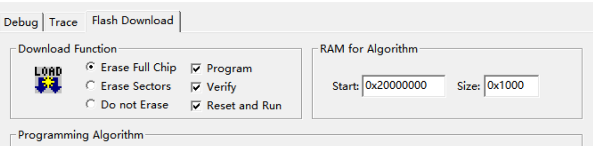
2. Disabling a specific IO port makes it impossible to burn
(my own method is effective, but I don't know which step is effective)
Change BOOT0 of the system board from 0 to 1 (boot1=0), SWD can be detected, and then set Erase Full Chip as shown in the figure
download a normal program with a GPIO_PinRemapConfig(GPIO_Remap_SWJ_Disable, DISABLE); [GPIO_PinRemapConfig(GPIO_Remap_SWJ_Disable, DISABLE) was used at that time, so it could not be downloaded. Use it with caution!]
boot0=0, can burn normally!
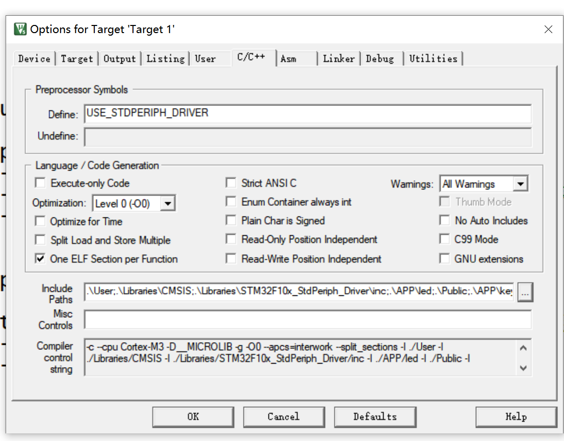
3.ZET changed to C8T6
1. The startup file changes. hd to. md
2.Device: ZET->C8
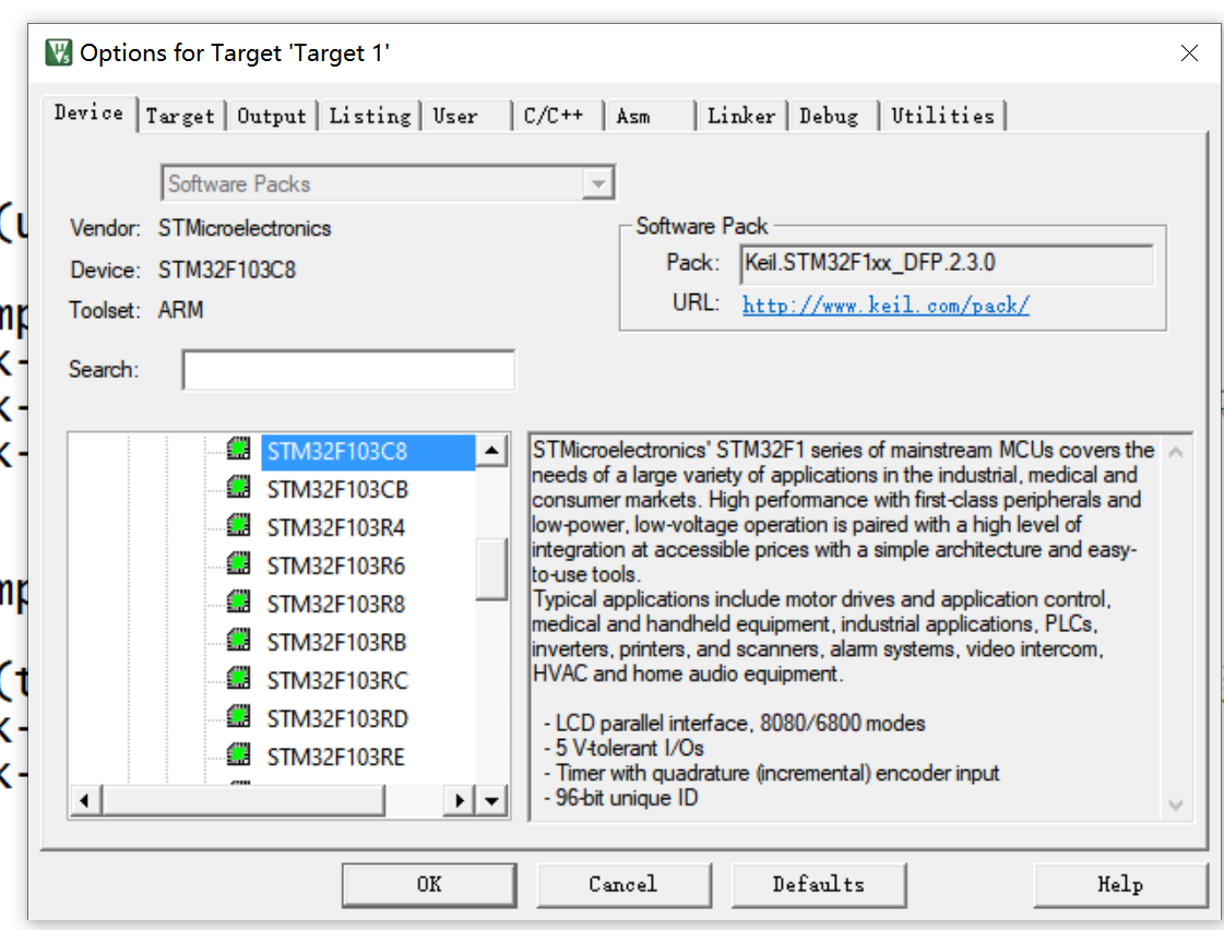
3.C/C++:USE_STDPERIPH_DRIVER
reference resources
Puzhong, punctual atom, wildfire related video, ppt, code