Key KEY interrupt mode to control LED
Interrupt firmware libraries stm32f10x_exti.h and stm32f10x_exti.c
Each IO of STM32 can be used as an interrupt input for external interrupts, which is also the strength of STM32. The STM32F103 interrupt controller supports 19 external interrupt event requests. Each interrupt has a status bit, and each interrupt/event has its own trigger and shield settings. Nineteen external interruptions of STM32F103 were:
- Line 0-15: Input interruption corresponding to external IO port.
- Line 16: Connect to PVD output.
- Line 17: Connect to RTC alarm clock event.
- Line 18: Connect to a USB wake-up event.
GPIO x.0~GPIOx.15 (x=A, B, C, D, E, F,G) of GPIO corresponds to 0-15 of interruption line (mapping diagram of GPIO and interruption line)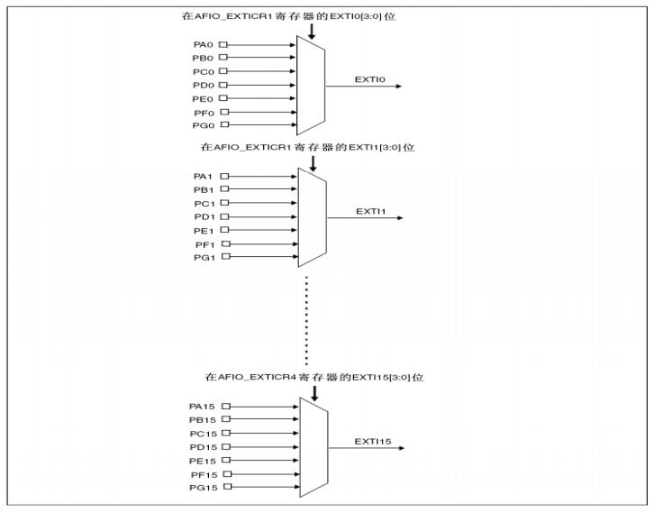
General steps for using external interrupt of IO port:
1) Initialize the IO port as input.
RCC_APB2PeriphClockCmd(RCC_APB2Periph_GPIOE|RCC_APB2Periph_AFIO,ENABLE);
//Here, PGIO is not only used as normal input and output, but also as interrupt. RCC_APB2Periph_AFIO needs to be mounted.
//Configure key
  GPIO_InitTypeDef GPIO_InitTypeDef_PE4 ;
  GPIO_InitTypeDef_PE4 .GPIO_Pin = GPIO_Pin_4;//PE4
  GPIO_InitTypeDef_PE4 .GPIO_Mode = GPIO_Mode_IPU;//Pull up input
  GPIO_Init(GPIOE,&GPIO_InitTypeDef_PE4 );
2) Open the IO multiplexing clock and set the mapping relationship between IO port and interrupt line.
     void GPIO_EXTILineConfig(uint8_t GPIO_PortSource, uint8_t GPIO_PinSource);
     /*
     GPIO_PortSource For GPIO_PortSource GPIO (A-G)
     GPIO_PinSource   For GPIO_PinSource(0-15)
     How to configure that port is shown in the figure above (mapping between GPIO and interrupt line):
      For example, PA5 1. GPIO_PortSource is GPIO_PortSource GPIOA
                  2. GPIO_PinSource For GPIO_PinSource5
     */
3) Interruption on initialization line, setting trigger condition, etc.
  //External i/o interrupt configuration
  EXTI_InitTypeDef EXTI_ITDef;
  //This function maps the GPIO port to the interrupt line
  GPIO_EXTILineConfig(GPIO_PortSourceGPIOE,GPIO_PinSource4);
  EXTI_ITDef.EXTI_Line = EXTI_Line4;
  EXTI_ITDef.EXTI_Mode = EXTI_Mode_Interrupt;//Setting EXTI Line to Interrupt Request
  EXTI_ITDef.EXTI_Trigger=EXTI_Trigger_Falling;//Setting input line descent edge to interrupt request
  EXTI_ITDef.EXTI_LineCmd = ENABLE;//Define the new state of the selected line
  EXTI_Init(&EXTI_ITDef);
4) Configure interrupt grouping (NVIC) and enable interruption.
 //Interrupt Management NVIC
  NVIC_InitTypeDef  NVIC_ITDef;
  NVIC_PriorityGroupConfig(NVIC_PriorityGroup_2); //Setting 2:2 Bit Preemption Priority and 2 Bit Response Priority for NVIC Interrupt Groups
  NVIC_ITDef.NVIC_IRQChannel = EXTI4_IRQn;//Enabling key external interrupt channel
  NVIC_ITDef.NVIC_IRQChannelPreemptionPriority = 0x02; //Preemption priority 2
  NVIC_ITDef.NVIC_IRQChannelSubPriority = 0x00;//Subpriority 2
  NVIC_ITDef.NVIC_IRQChannelCmd = ENABLE;//Enabling external interruption of channels
  NVIC_Init(&NVIC_ITDef);
5) Write interrupt service function.
The commonly used interrupt service function format is:
void EXTI2_IRQHandler(void)
 {
    if(EXTI_GetITStatus(EXTI_Line3)!=RESET)// Determine whether an interrupt occurs on a line
    {
       // Interrupt logic...
       EXTI_ClearITPending Bit (EXTI_Line3); //Clear the interrupt flag on LINE
   }
 }
KEY(PE4) interrupt mode control LED(PB5) code
#include "stm32f10x.h"
void LED_Ioinit(void)
{
  //Mount PE5 to clock
  RCC_APB2PeriphClockCmd(RCC_APB2Periph_GPIOE,ENABLE);
  GPIO_InitTypeDef GPIO_ITYPD;
  GPIO_ITYPD.GPIO_Pin=GPIO_Pin_5;//port
  GPIO_ITYPD.GPIO_Mode=GPIO_Mode_Out_PP;//Pattern
  GPIO_ITYPD.GPIO_Speed=GPIO_Speed_2MHz;//speed
  GPIO_Init(GPIOE,&GPIO_ITYPD);//Set PB5

  GPIO_SetBits(GPIOE,GPIO_Pin_5); //BSRR  1
//GPIO_ResetBits(GPIOE,GPIO_Pin_5); //BRR  0
}
void EXTI_Init_k0(void)
{
  //External i/o interrupt configuration
  EXTI_InitTypeDef EXTI_ITDef;
  //This function maps the GPIO port to the interrupt line
  GPIO_EXTILineConfig(GPIO_PortSourceGPIOE,GPIO_PinSource4);
  EXTI_ITDef.EXTI_Line = EXTI_Line4;
  EXTI_ITDef.EXTI_Mode = EXTI_Mode_Interrupt;//Setting EXTI Line to Interrupt Request
  EXTI_ITDef.EXTI_Trigger=EXTI_Trigger_Falling;//Setting input line descent edge to interrupt request
  EXTI_ITDef.EXTI_LineCmd = ENABLE;//Define the new state of the selected line
  EXTI_Init(&EXTI_ITDef);

  //Interrupt Management NVIC
  NVIC_InitTypeDef NVIC_ITDef;
  NVIC_PriorityGroupConfig(NVIC_PriorityGroup_2); //Setting 2:2 Bit Preemption Priority and 2 Bit Response Priority for NVIC Interrupt Groups
  NVIC_ITDef.NVIC_IRQChannel = EXTI4_IRQn;//Enabling key external interrupt channel
  NVIC_ITDef.NVIC_IRQChannelPreemptionPriority = 0x02; //Preemption priority 2
  NVIC_ITDef.NVIC_IRQChannelSubPriority = 0x00;//Subpriority 2
  NVIC_ITDef.NVIC_IRQChannelCmd = ENABLE;//Enabling external interruption of channels
  NVIC_Init(&NVIC_ITDef);
}
void delay_ms(u16 time)
{
   u16 i = 0;
   while(time--)
   {
      i = 12000;
      while(i--);
   }
}
void delay_us(u16 time)
{
   u16 i = 0;
   while(time--)
   {
      i=10;
      while(i--);
   }
}
void KEY_Init(void)
{
  //Configure PE Clock//Configure Multiplexed Clock
  RCC_APB2PeriphClockCmd(RCC_APB2Periph_GPIOE|RCC_APB2Periph_AFIO,ENABLE);
   //Configure key
  GPIO_InitTypeDef GPIO_ITYPD1;
  GPIO_ITYPD1.GPIO_Pin = GPIO_Pin_4;
  GPIO_ITYPD1.GPIO_Mode = GPIO_Mode_IPU;//Pull up input
  GPIO_Init(GPIOE,&GPIO_ITYPD1);

}
//The service function of external interrupt 4 is responsible for interrupt detection of KEY keys.
void EXTI4_IRQHandler(void)
{
    if(EXTI_GetITStatus(EXTI_Line4)!=RESET)//Determine whether an interrupt on a line occurs
   {
     delay_ms(15);
     if(!(GPIO_ReadInputDataBit(GPIOE,GPIO_Pin_4)))//0X00
     {
       if(GPIO_ReadOutputDataBit(GPIOE,GPIO_Pin_5))//0X01
       {
         GPIO_ResetBits(GPIOE,GPIO_Pin_5); //BRR  0
       }else
       {
         GPIO_SetBits(GPIOE,GPIO_Pin_5);  //BSRR  1
       }
     }
    EXTI_ClearITPendingBit(EXTI_Line4);
   }
}
int main(void)
{
  while(1);
}
Related documents
STM32 V3.5 firmware library function call instructions (Chinese version)
STM32F10x_StdPeriph_Lib_V3.5.0 (Official Firmware Library)