STM32 interrupt, DMA communication principle and programming method example
STM32 interrupt, DMA communication principle and programming method example
1 Introduction to interrupt
1.1 concept
Interrupt actually means that when the CPU executes a program, due to some random event (external or internal), the CPU temporarily interrupts the running program and turns to execute a special service program (interrupt service subroutine or interrupt handler) to deal with the event. After the event is processed, it returns to the interrupted program to continue to execute. This process is called interrupt, The place that causes an interrupt is called the interrupt source.
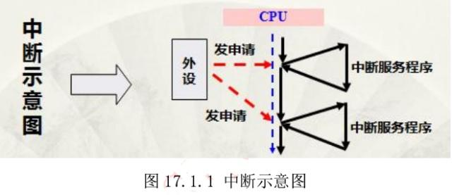
For example, when the doorbell rings suddenly while watching TV, the doorbell ring is equivalent to the interrupt source. Some interrupts can also be interrupted by other high priority interrupts, which is also called interrupt nesting.
Meaning of interrupt: it can save CPU memory.
Interrupt condition: fast in and fast out
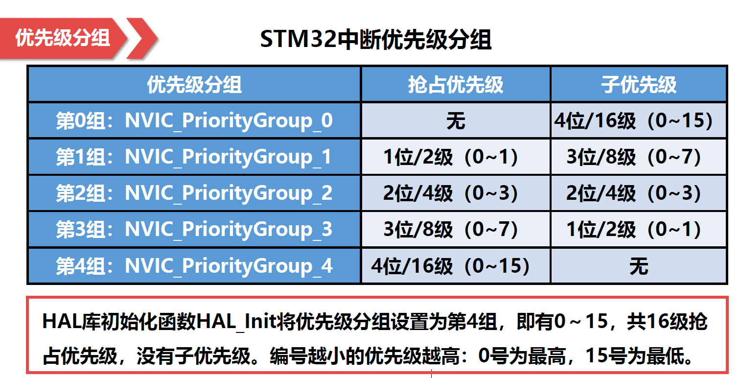
1.1.1 interrupt priority
- When multiple interrupts apply for interrupts at the same time: compare the preemption priority first, and the interrupts with high preemption priority will be executed first. If the preemption priorities are the same, the sub priorities are compared.
- Both are the same, compare the interrupt number (the interrupt number is in the chip header file). The smaller the number, the higher the priority.
1.1.2 external interrupt EXIT
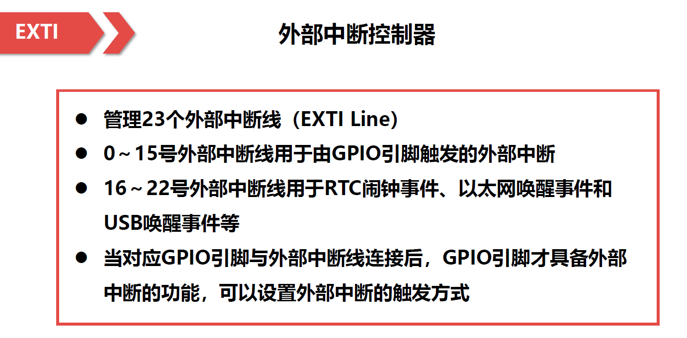
External interrupt program design idea:
Interrupt initialization mainly improves three structures:
①GPIO_InitTypeDef (function: IO configuration)
②EXTI_InitTypeDef (function: interrupt configuration)
③NVIC_InitTypeDef (function: interrupt priority configuration)
1.2 control of interruption
The full English name of NVIC is nested vector interrupt controller, which means nested vector interrupt controller in Chinese. It belongs to a peripheral of M3 kernel and controls the interrupt related functions of the chip.
The number of internal interrupts of STM32F103 chip of ST company is the result of NVIC cutting.
In the firmware library core_cm3.h file defines an NVIC structure, which defines relevant registers,
1 typedef struct

2 {

3 __IO uint32_t ISER[8]; /*!< Offset: 0x000 Interrupt Set Enable Register */

4 uint32_t RESERVED0[24];

5 __IO uint32_t ICER[8]; /*!< Offset: 0x080 Interrupt Clear Enable Register */

6 uint32_t RSERVED1[24];

7 __IO uint32_t ISPR[8]; /*!< Offset: 0x100 Interrupt Set Pending Register */

8 uint32_t RESERVED2[24];

9 __IO uint32_t ICPR[8]; /*!< Offset: 0x180 Interrupt Clear Pending Register */

10 uint32_t RESERVED3[24];

11 __IO uint32_t IABR[8]; /*!< Offset: 0x200 Interrupt Active bit Register */

12 uint32_t RESERVED4[56];

13 __IO uint8_t IP[240]; /*!< Offset: 0x300 Interrupt Priority Register (8Bit wide) */

14 uint32_t RESERVED5[644];

15 __O uint32_t STIR; /*!< Offset: 0xE00 Software Trigger Interrupt Register */

16 } NVIC_Type;
When configuring interrupts, we usually use only three registers: ISER, ICER and IP. ISER is the interrupt enable register, ICER is the interrupt clear register and IP is the interrupt priority register.
1.3 interrupt configuration
(1) Enable a peripheral interrupt
(2) Set interrupt priority grouping
(3) Write interrupt service function
2 DMA communication principle and programming method
2.1 serial port interrupt
- Serial port interrupt is the interrupt that enters the serial port when the data register is not empty.
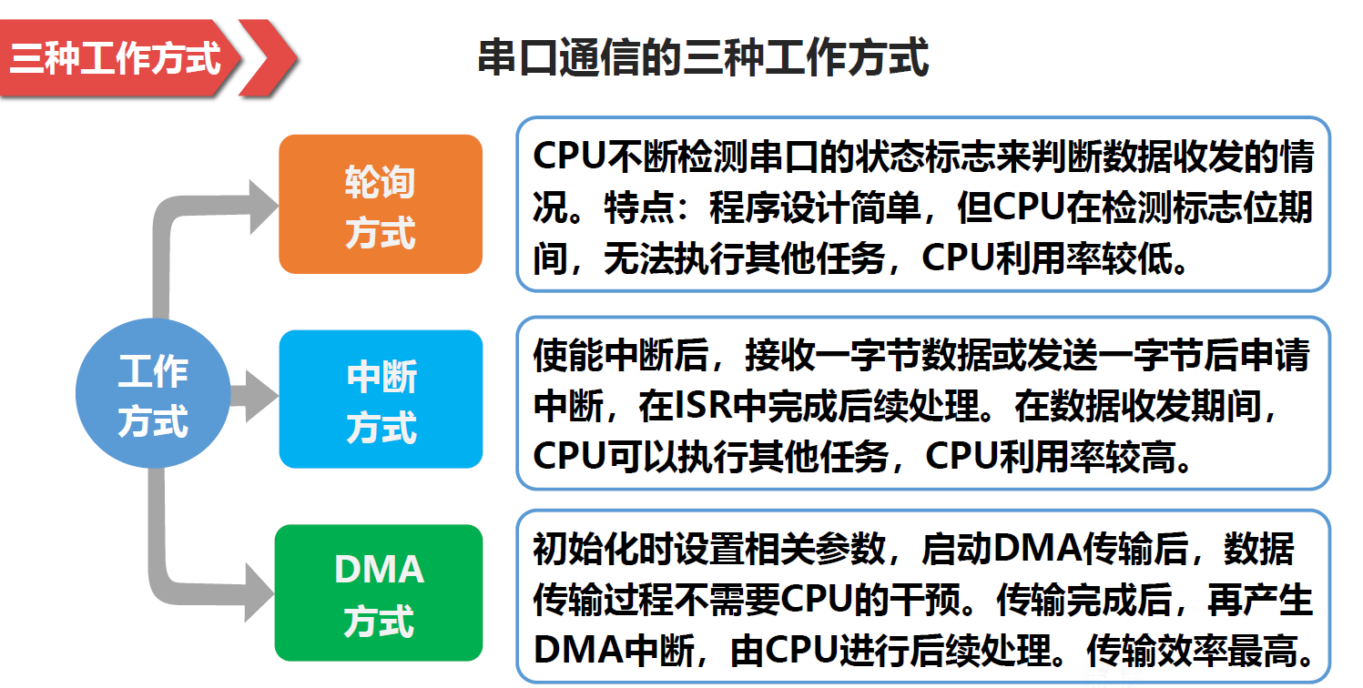
- Serial communication classification
- Related functions of serial port interrupt:
| Serial number | Function name | expression |
|---|---|---|
| 1 | Serial port interrupt mode sending function | HAL_UART_Transmit_IT |
| 2 | Serial port interrupt mode receiving function | HAL_UART_Receive_IT |
| 3 | General processing function of serial port interrupt | HAL_UART_IRQHandler |
| 4 | Serial port sending interrupt callback function | HAL_UART_TxCpltCallback |
| 5 | Serial port receive interrupt callback function | HAL_UART_RxCpltCallback |
| 6 | Serial port interrupt enable function | __HAL_UART_ENABLE_IT |
| 7 | Serial port interrupt flag query function | __HAL_UART_GET_FLAG |
| 8 | Idle interrupt flag clearing function | __HAL_UART_CLEAR_IDLEFLAG |
2.2 DMA concept
-
Direct memory access (DMA): used for high-speed data transmission between peripherals and memory and between memory and memory. The initialization and startup of DMA transfer process are controlled by CPU
The transmission process is executed by the DMA controller without CPU participation, so as to save CPU resources and improve utilization.When the amount of data transmitted is large and the communication baud rate is high (greater than 38400), if the interrupt mode is adopted, the CPU will be interrupted every byte of data sent and received, resulting in CPU failure
Unable to process other transactions. Therefore, DMA mode is recommended when batch data transmission and communication baud rate is high. -
Four elements of DMA data transmission:
① Transmission source the source of DMA data transmission
② Transmission target: the purpose of DMA data transmission
③ Transmission quantity: the quantity of DMA transmission data
④ Trigger signal: the action of starting a DMA data transmission -
DMA mode interface function
| Serial number | Function name | expression |
|---|---|---|
| 1 | Serial port DMA mode transmission function | HAL_UART_Transmit_DMA |
| 2 | Serial port DMA mode receiving function | HAL_UART_Receive_DMA |
| 3 | Function to get the number of untransmitted data | __HAL_DMA_GET_COUNTER |
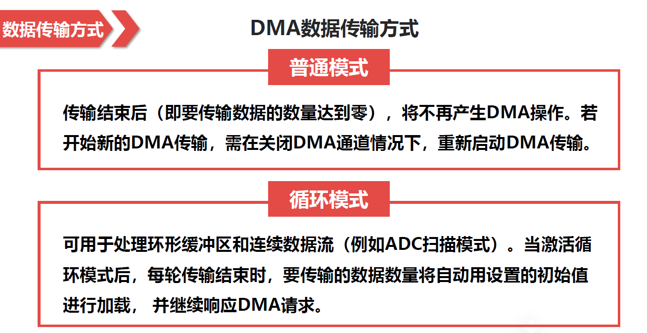
- DMA data transmission mode
- DMA usage steps
Step 1: enable the DMA clock and wait for the data stream to be configurable.
Step 2: DMA_ Sxcr (specified peripheral – x) sets the stream x, including configuration channel, peripheral address, memory address, transmission data volume, priority, etc.
Step 3: enable the DMA function of the peripheral
Step 4: enable DMA data stream and start transmission.
Step 5: query DMA transmission status.
3 example 1
Learn stm32 interrupt, DMA communication principle and programming method. Complete the following programming exercises using stm32tubemx and HAL libraries:
Title: use one pin of the GPIOA end of the stm32F103 core board to connect an LED, and one pin of the GPIOB port to connect a switch (replaced by DuPont line simulation). Interrupt mode programming is adopted. When the switch is connected to high level, the LED lights up; When connected to low level, the LED is off.
3.1 establishment of engineering documents
-
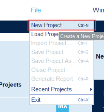
Open STM32CubeMX software and create a new project file
-
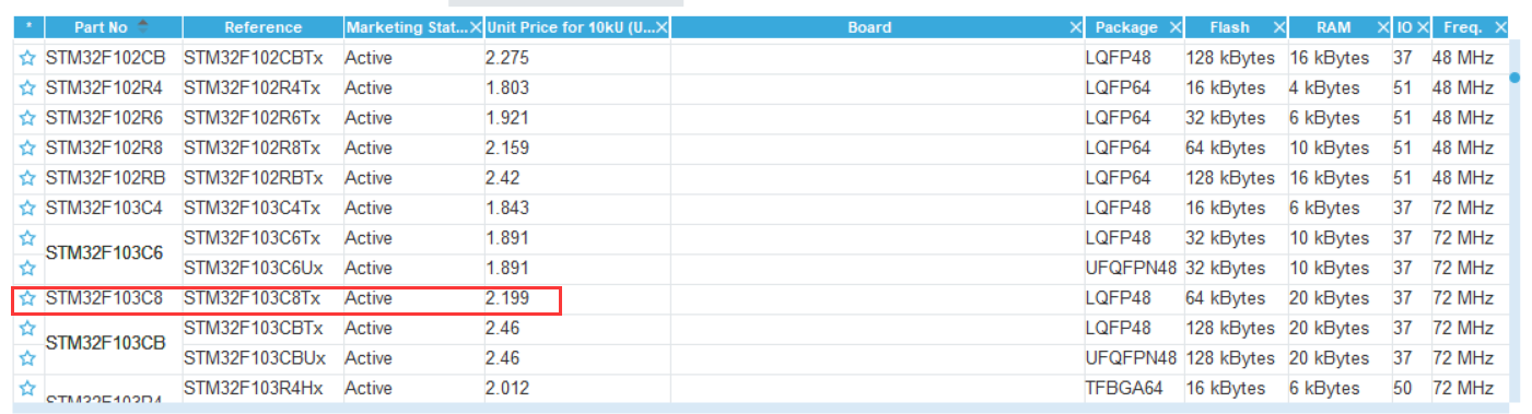
Select chip STM32F103C8
-
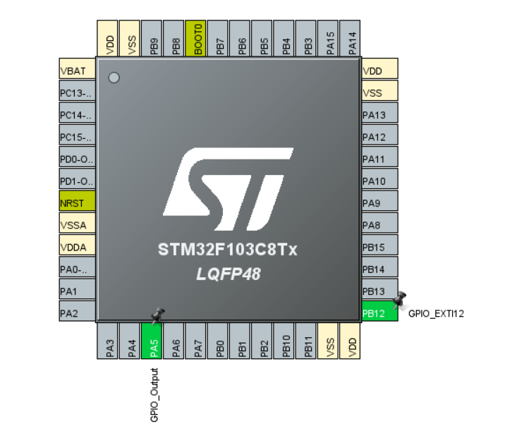
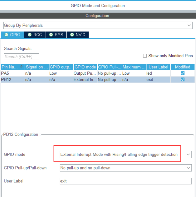
Pin configuration:
PA5 set to GPIO_Output, as the LED lamp control pin
PB12 set to GPIO_EXIT12, as the switch control pin.
-
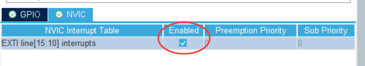
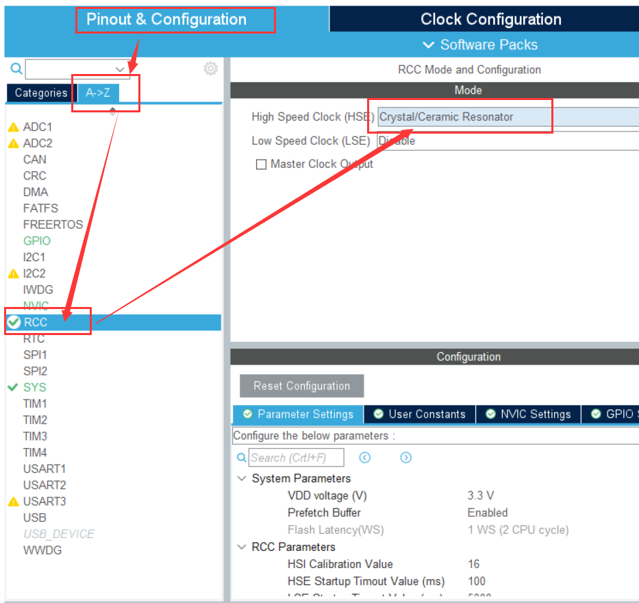
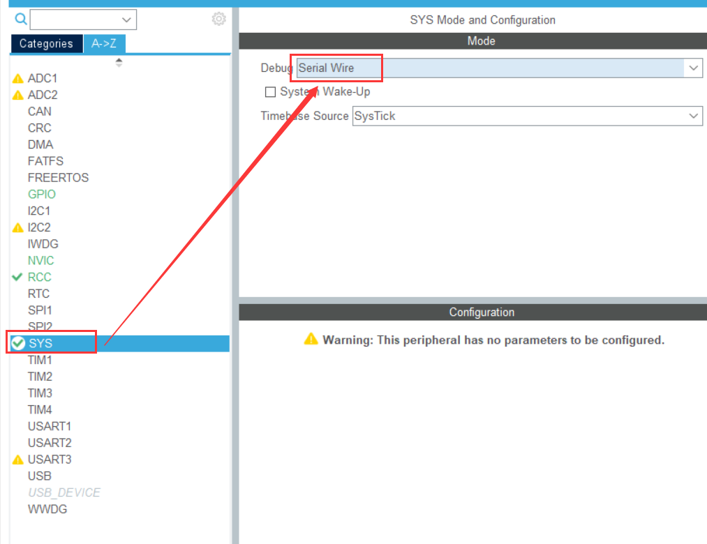
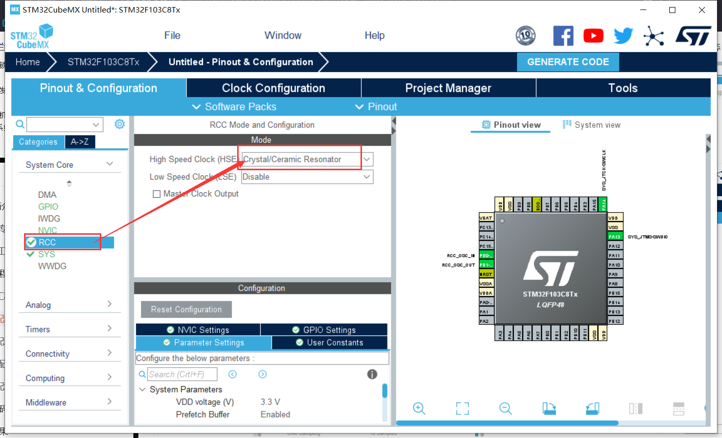
Peripheral configuration:
Set the interrupt pin to trigger on the rising and falling edges.
Enable medium break.
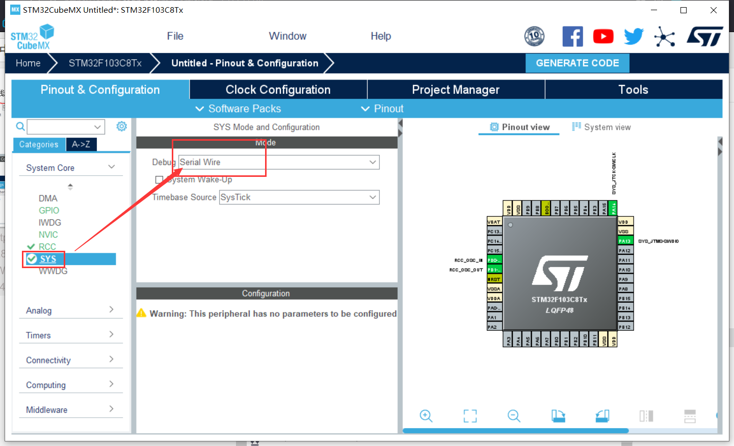
RCC settings.
SYS settings.
-
Clock configuration:
Set to 36 MHz.
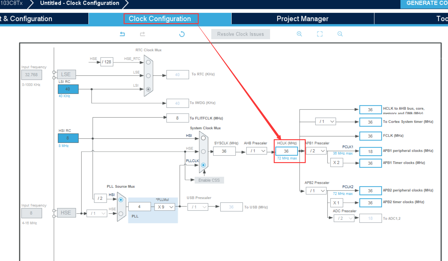
-
engineering management
Similar to the previous article[ Serial port protocol, stm32CubeMX instance and keil waveform observation] -
Generate code

3.2 coding
Write the terminal services function in the main.c file.
void HAL_GPIO_EXTI_Callback(uint16_t GPIO_Pin)
{
	if( GPIO_Pin == exit_Pin)  //Determine external interrupt source
	{
		HAL_GPIO_TogglePin(led_GPIO_Port, led_Pin);   //Flip LED status
	}
}
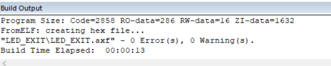
The build has no errors.
3.3 burning
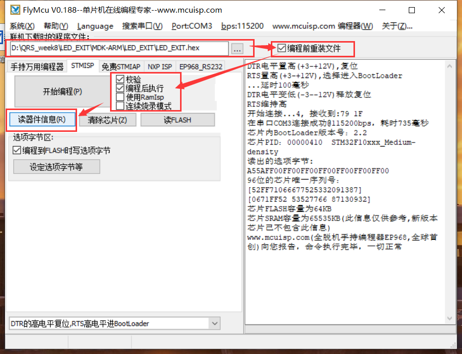
Successfully burned!
3.4 test results
4 Example 2
[redo the serial communication operation of last week by means of serial port interrupt.]
Last week's topic:
Complete a USART serial port communication program of STM32 (query mode is OK, interrupt mode is not required temporarily). Requirements:
1) Set the baud rate to 115200, 1 stop bit and no check bit;
2) STM32 system continuously sends "hello windows!" to the upper computer (win10). Win10 uses the "serial port assistant" tool to receive.
4.1 establishment of engineering documents
-
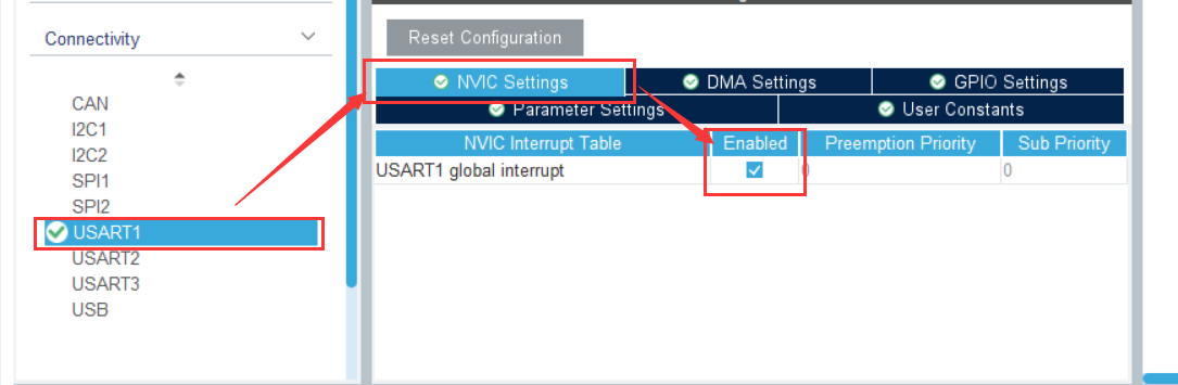
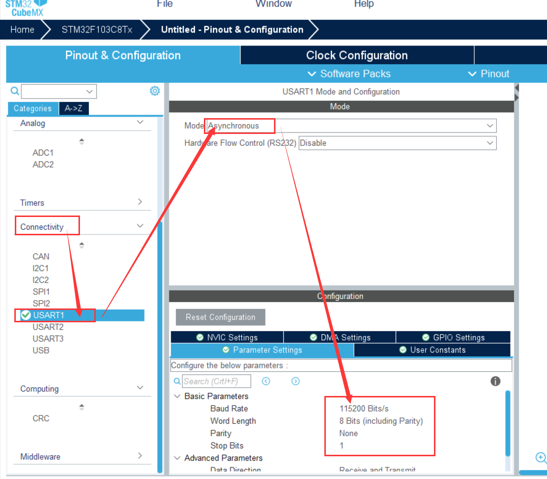
Set RCC and SYS, and then set USART1 as follows:
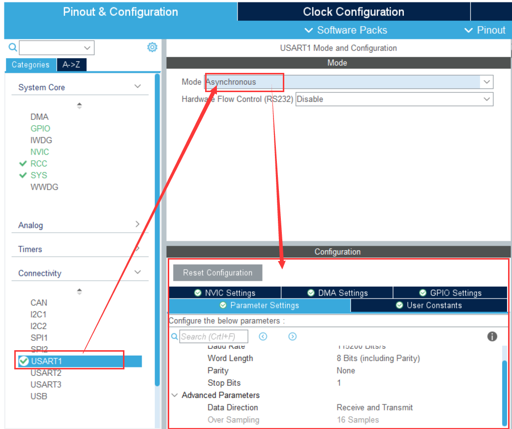
Enable USART1.
-
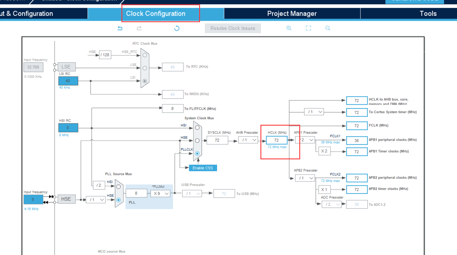
Clock configuration
72MHz
-
engineering management
-
Generate code

4.2 coding
Add header file #include "stdio.h" in main.c and usart.c
Add code in usart.c:
//Add the following code to support the printf function without selecting use MicroLIB
//#define PUTCHAR_PROTOTYPE int fputc(int ch, FILE *f)
#if 1
//#pragma import(__use_no_semihosting)
//Support functions required by the standard library
struct __FILE
{
	int handle;
};

FILE __stdout;
//Define _sys_exit() to avoid using half host mode
void _sys_exit(int x)
{
	x = x;
}
//Redefine fputc function
int fputc(int ch, FILE *f)
{
	 HAL_UART_Transmit(&huart1, (uint8_t *)&ch, 1, 0x0001);
	return ch;
}
#endif
Add codes respectively in main.c
//Add to the while function
	  	printf("Hello windows!\r\n");
		HAL_Delay(500);
uint8_t aRxBuffer;			//Receive interrupt buffer
uint8_t Uart1_RxBuff[256];		//Receive buffer
uint8_t Uart1_Rx_Cnt = 0;		//Receive buffer count
uint8_t	cAlmStr[] = "data overflow (Greater than 256)\r\n";
HAL_UART_Receive_IT(&huart1, (uint8_t *)&aRxBuffer, 1); //Enable receive interrupt
//Interrupt callback function

/**
  * @brief  Rx Transfer completed callbacks.
  * @param  huart pointer to a UART_HandleTypeDef structure that contains
  *                the configuration information for the specified UART module.
  * @retval None
  */
void HAL_UART_RxCpltCallback(UART_HandleTypeDef *huart)
{
  /* Prevent unused argument(s) compilation warning */
  UNUSED(huart);
  /* NOTE: This function Should not be modified, when the callback is needed,
           the HAL_UART_TxCpltCallback could be implemented in the user file
   */

	if(Uart1_Rx_Cnt >= 255)  //Overflow judgment
	{
		Uart1_Rx_Cnt = 0;
		memset(Uart1_RxBuff,0x00,sizeof(Uart1_RxBuff));
		HAL_UART_Transmit(&huart1, (uint8_t *)&cAlmStr, sizeof(cAlmStr),0xFFFF);
	}
	else
	{
		Uart1_RxBuff[Uart1_Rx_Cnt++] = aRxBuffer;   //Receive data transfer

		if((Uart1_RxBuff[Uart1_Rx_Cnt-1] == 0x0A)&&(Uart1_RxBuff[Uart1_Rx_Cnt-2] == 0x0D)) //Judgment end bit
		{
			HAL_UART_Transmit(&huart1, (uint8_t *)&Uart1_RxBuff, Uart1_Rx_Cnt,0xFFFF); //Send the received information
			Uart1_Rx_Cnt = 0;
			memset(Uart1_RxBuff,0x00,sizeof(Uart1_RxBuff)); //Empty array
		}
	}

	HAL_UART_Receive_IT(&huart1, (uint8_t *)&aRxBuffer, 1);   //Restart receive interrupt
}
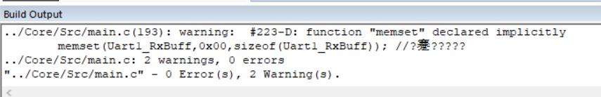
Compile build without errors:
4.3 burning
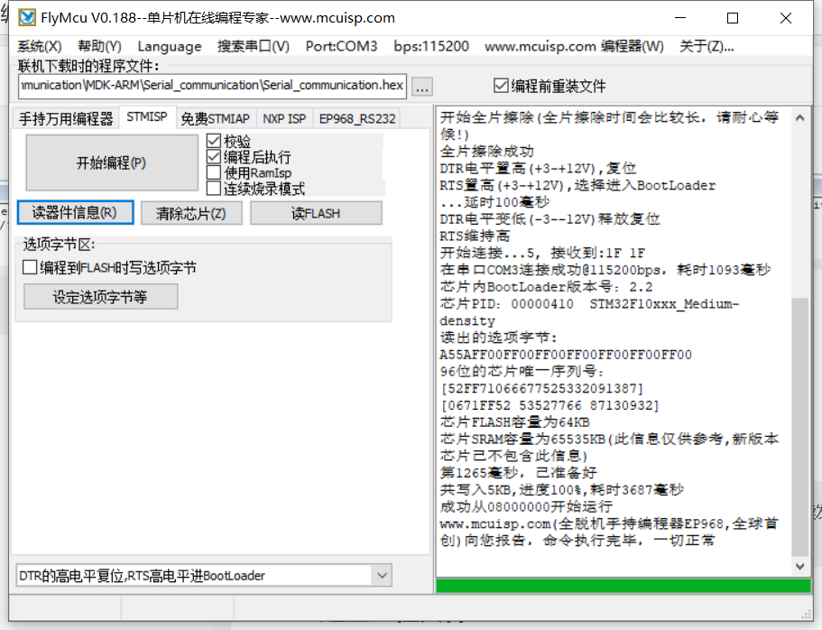 Successfully burned!
4.4 test results
Open the serial port assistant software: click [open serial port]
5 example III
Title: STM32 uses serial DMA to continuously send data to the host computer at 115200bps or higher rate.
5.1 establishment of engineering documents
-
Create project file: also select STM32F103C8
-
Configure peripherals:
RCC,SYS
Enable interrupt:
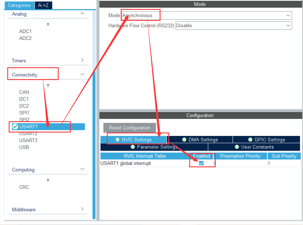
Set the baud rate to 115200 Bits/s and the transmission data length to 8 bits. Stop bit 1.
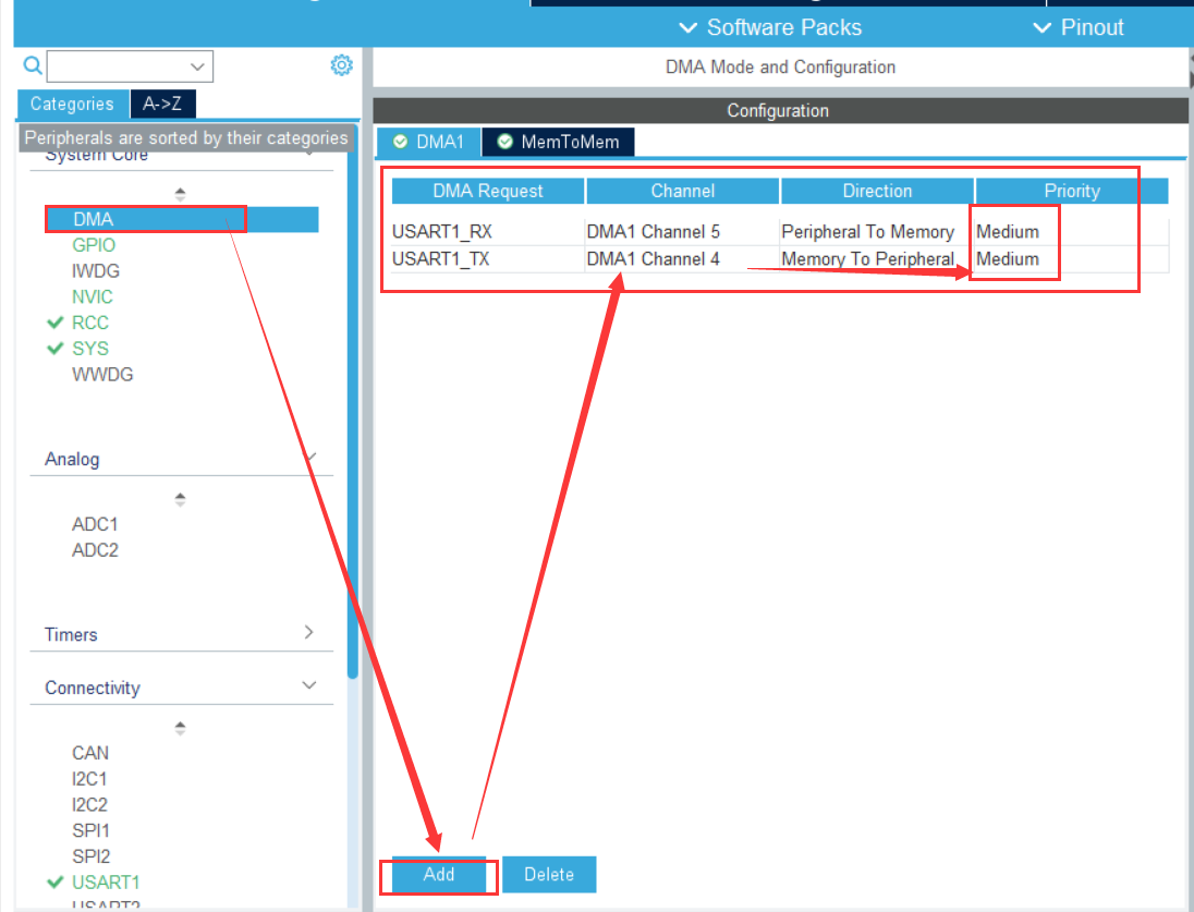
DMA configuration:
-
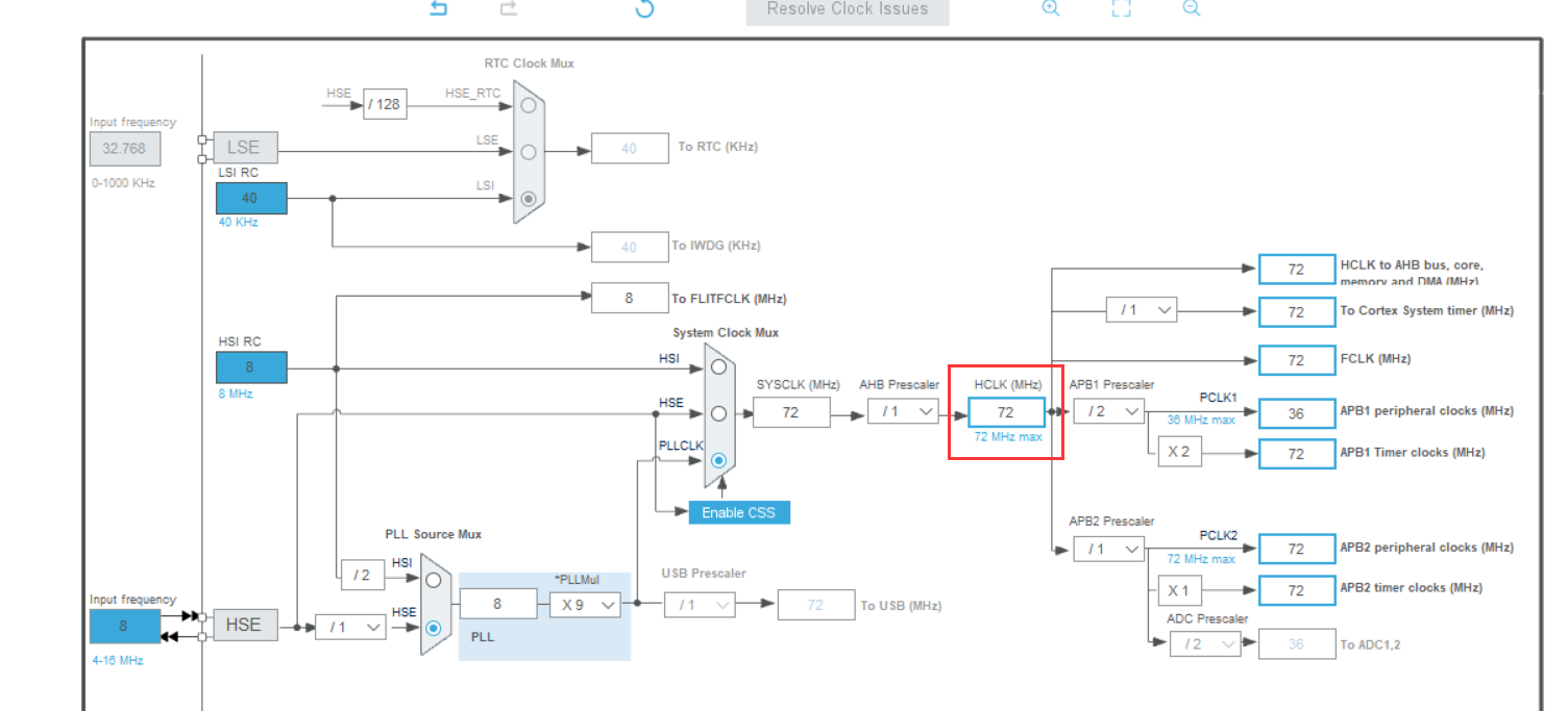
Clock configuration
72MHz
-
engineering management
-
Generate code
5.2 coding
Add the following code to the main.c file
uint8_t Senbuff[] = "\r\n(go for it)"; //Define data sending array
Add the following code to the while function:
			HAL_UART_Transmit_DMA(&huart1, (uint8_t *)Senbuff, sizeof(Senbuff));
	        HAL_Delay(1000);
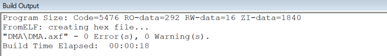
Compile build without errors.
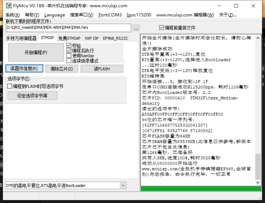
5.3 burning
Burning succeeded:
5.4 test results
Open the serial port assistant, add the HEX file, and click to open the serial port.
6 experimental summary
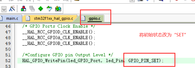
It is worth noting that in the setting of CubeMX, we must not forget what should be set at each step and the alias, which may be used in later programming. When lighting the small lamp, if it doesn't light up all the time, you can try to change the state of the lamp to see if another way can make the lamp light up. In addition, when adding user programs to keil, you should pay attention to where the programs should be. Failure to pay attention to the order will lead to errors in the use of functions.
7 references
Introduction to the interrupt concept of STM32 single chip microcomputer
EXIT of STM32 notes (external interrupt)
Understanding of DMA