STM32 interrupt and DMA communication programming
1, Topic content
Learn stm32 interrupt, DMA communication principle and programming method. Complete the following programming exercises using stm32tubemx and HAL libraries:
- One pin of the GPIOA end of the stm32F103 core board is connected to an LED, and one pin of the GPIOB port is connected to a switch (replaced by DuPont line simulation). Interrupt mode programming is adopted. When the switch is connected to high level, the LED lights up; When connected to low level, the LED is off.
- The serial port interrupt mode is adopted to redo the serial port communication operation last week.
- STM32 adopts serial port DMA mode and continuously sends data to the upper computer at a rate of 115200bps or higher.
2, CubeMX interrupt mode turns on the LED
1. CubeMX project
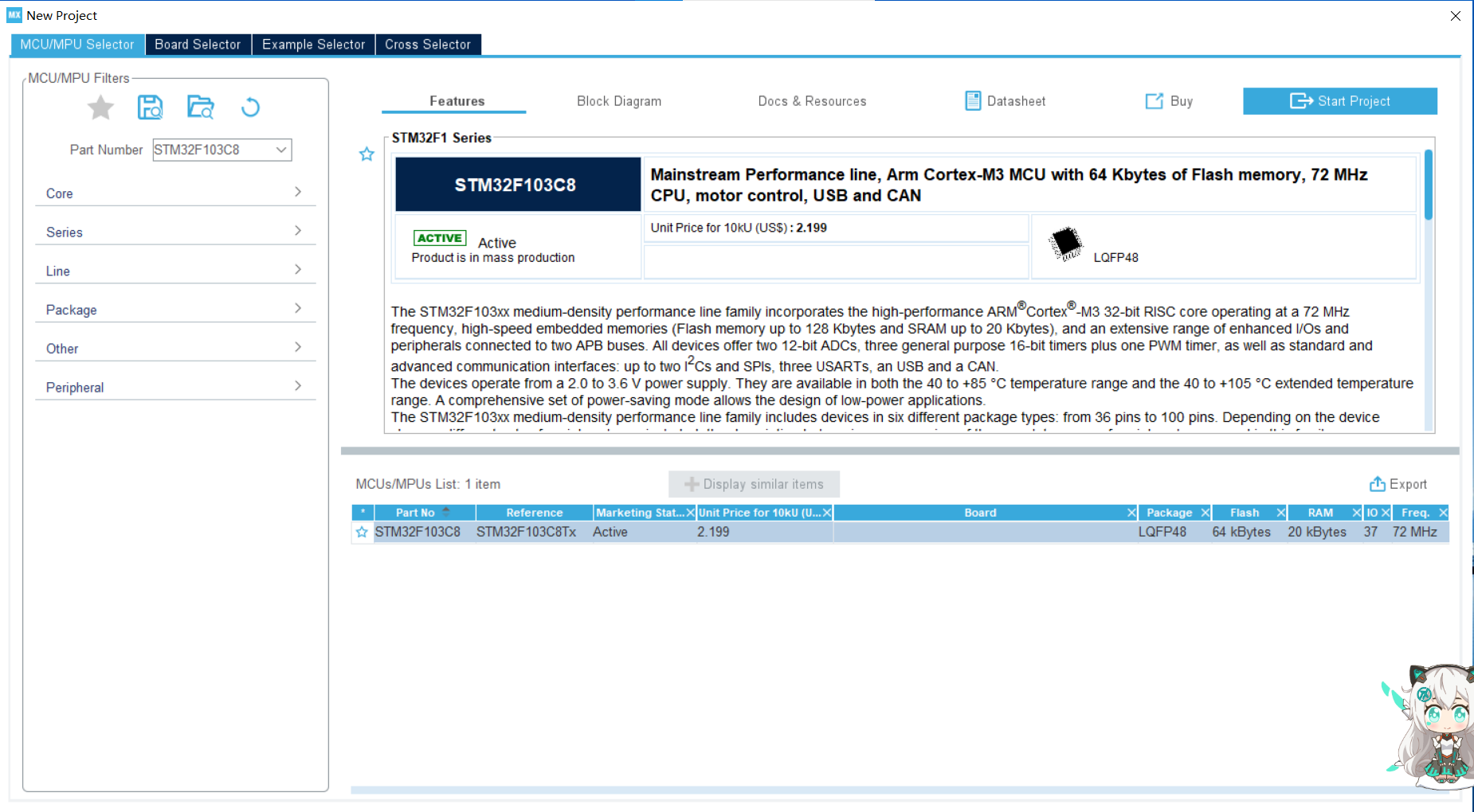
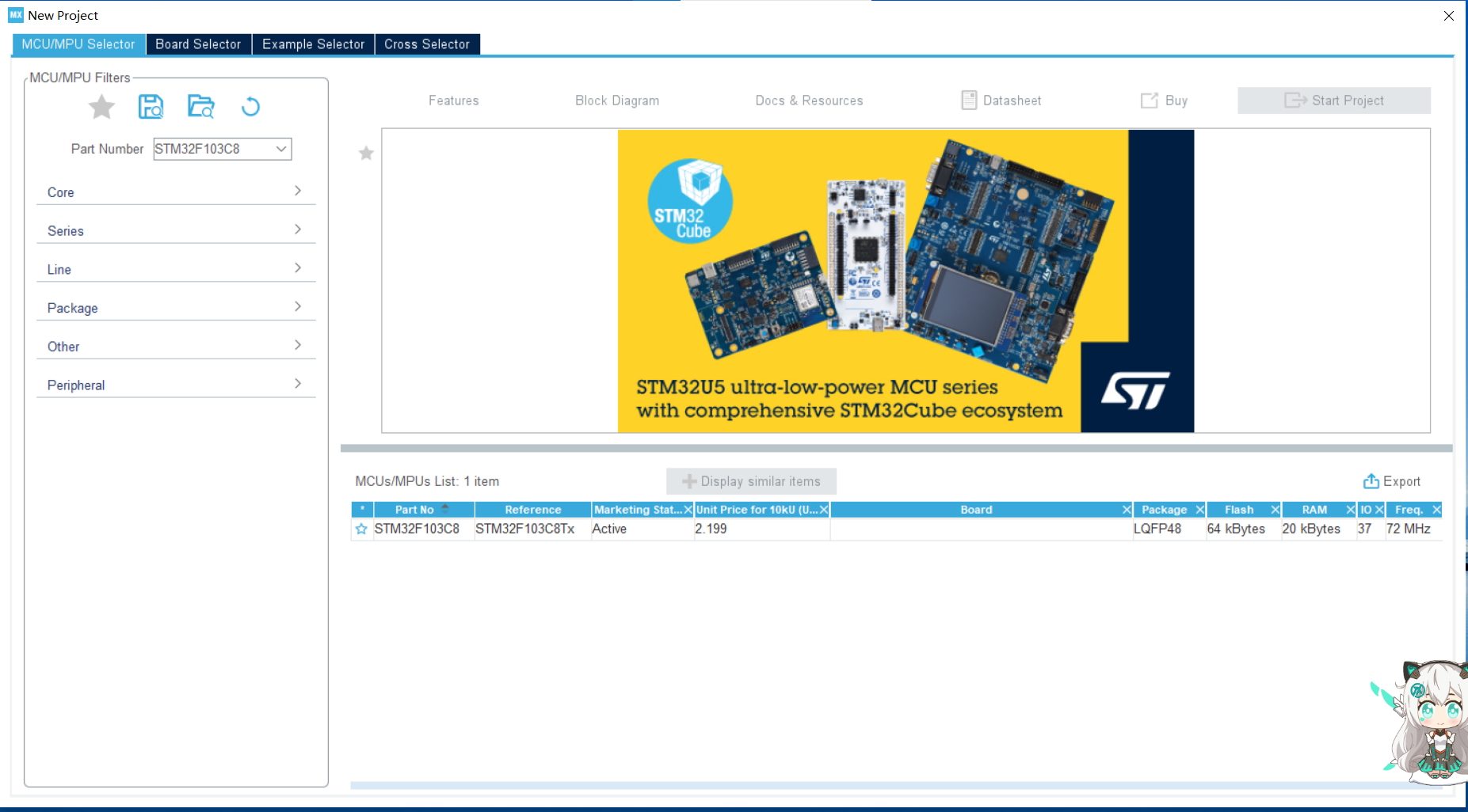
Enter stmsubemx and select a new project:

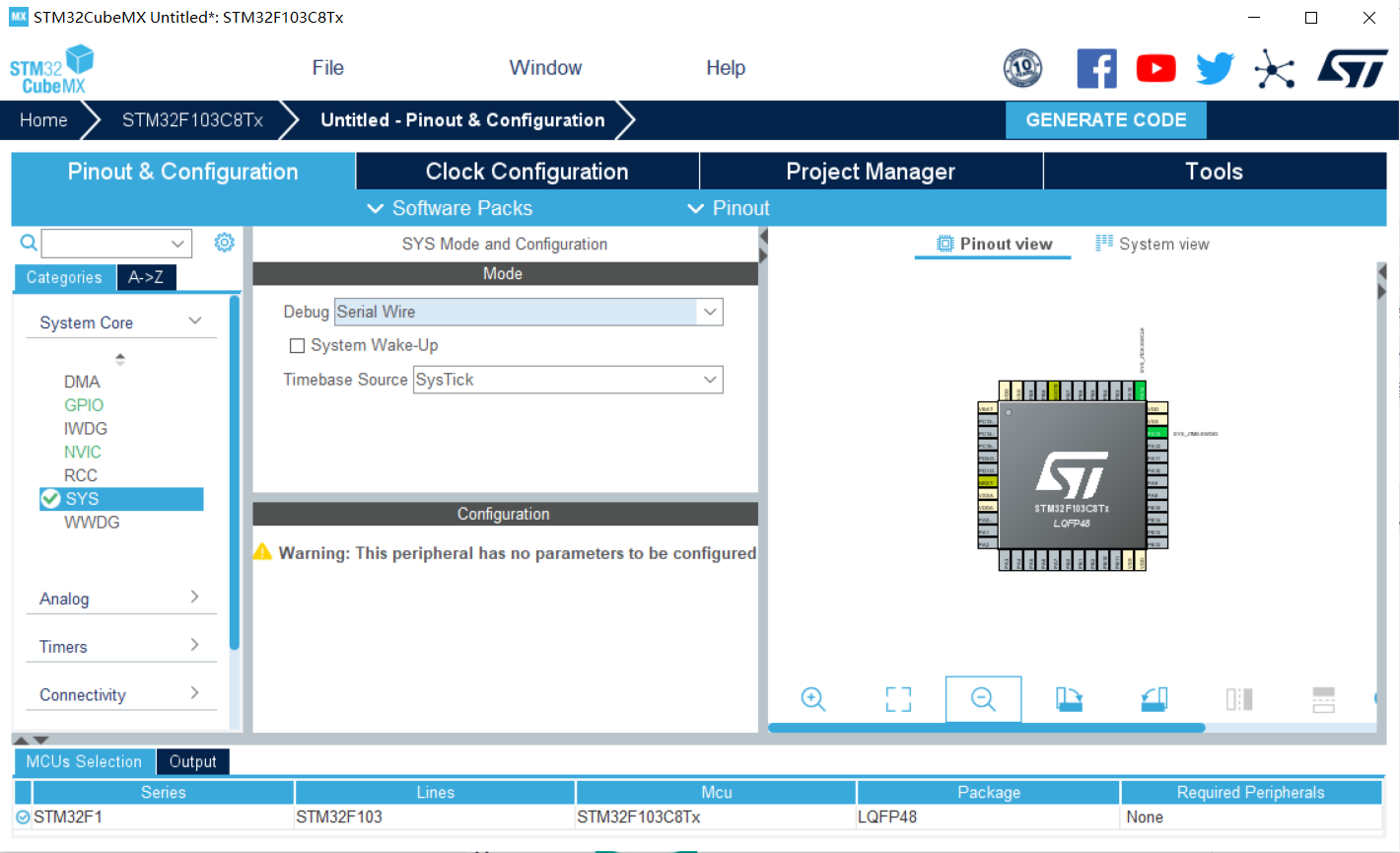
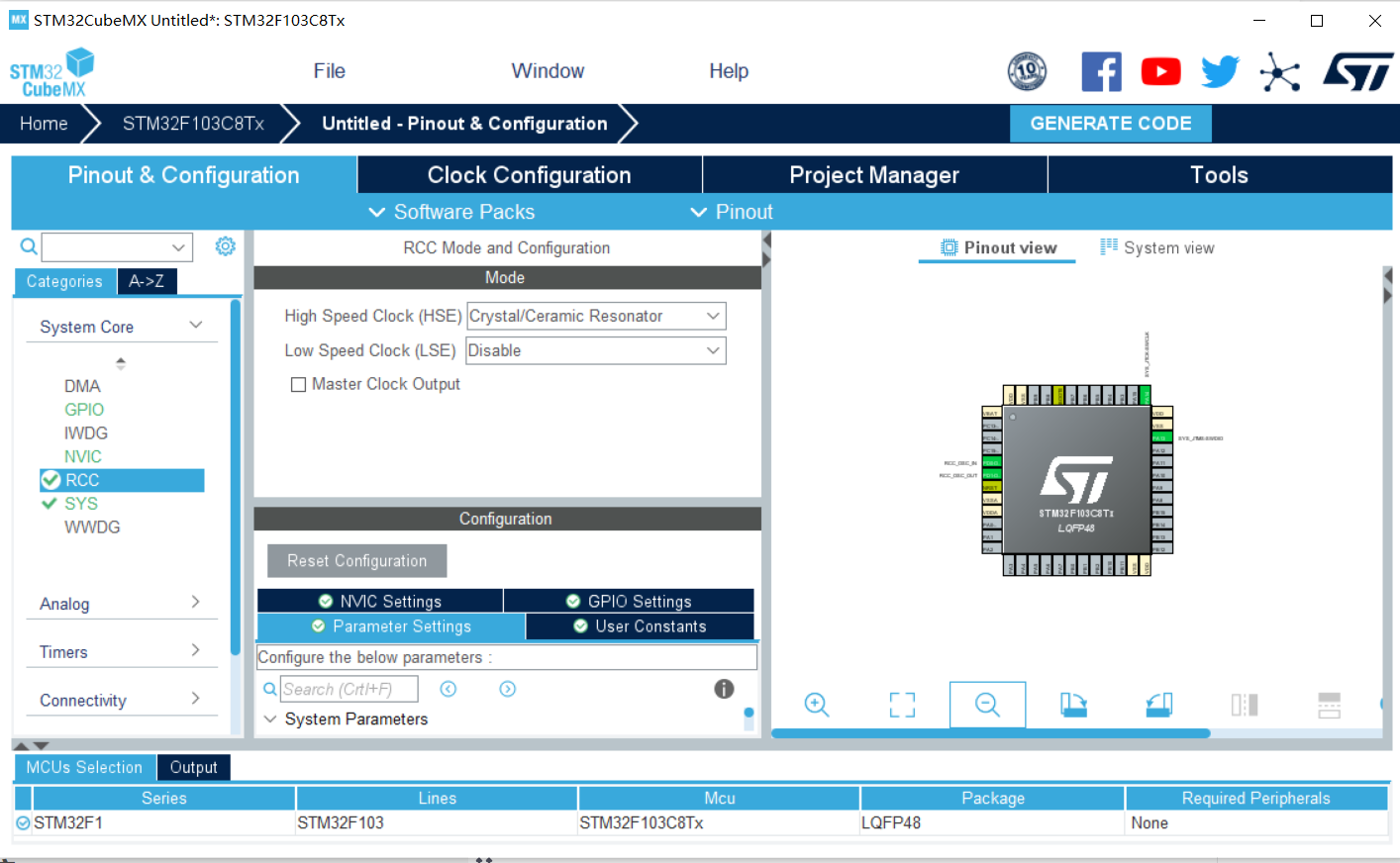
Click sys and change the debug option to Serial Wire.
Select Crystal/Ceramic Resonator for HSE in RCC

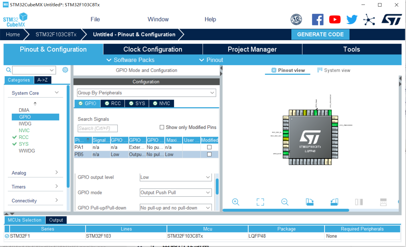
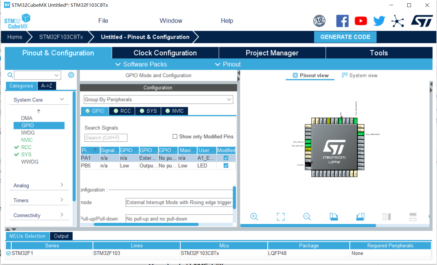
For the pin PA1 corresponding to the switch, set its trigger mode as rising edge trigger
External Interrupt Mode with Rising edge trigger detection Rising edge
External Interrupt Mode with Falling edge trigger detection Falling edge
External Interrupt Mode with Rising/Falling edge trigger detection Rising and falling edges
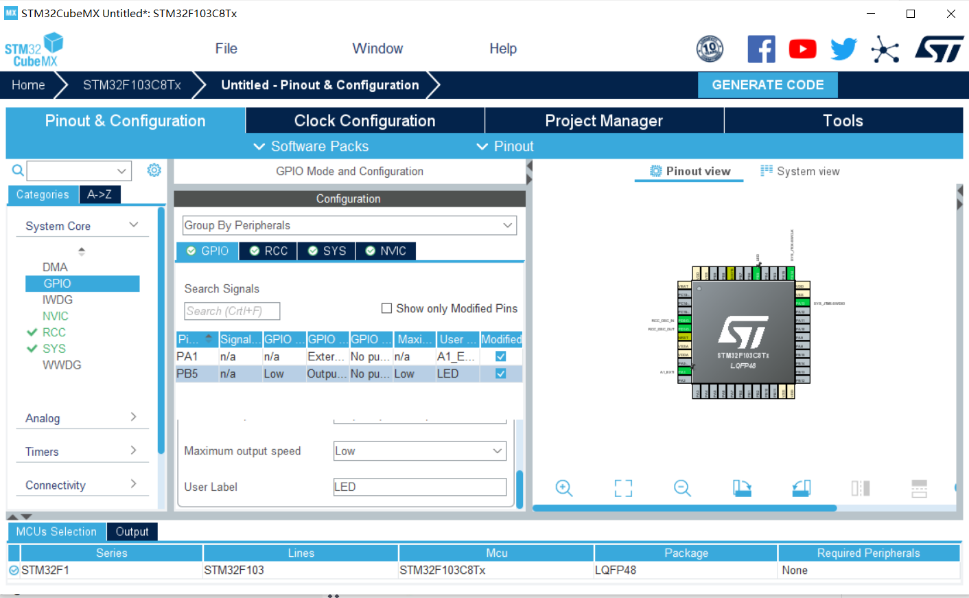
Set the name to A1 at the User Label_ EXTI:
Enable the corresponding external interrupt line and click Enabled
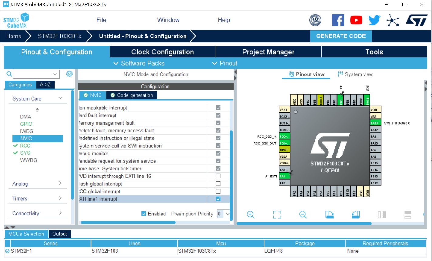
Configure interrupt priority
(in most cases, it is not necessary to set the interrupt priority, but directly use the default interrupt priority set by the interrupt number)

Clock setting: set to 36M

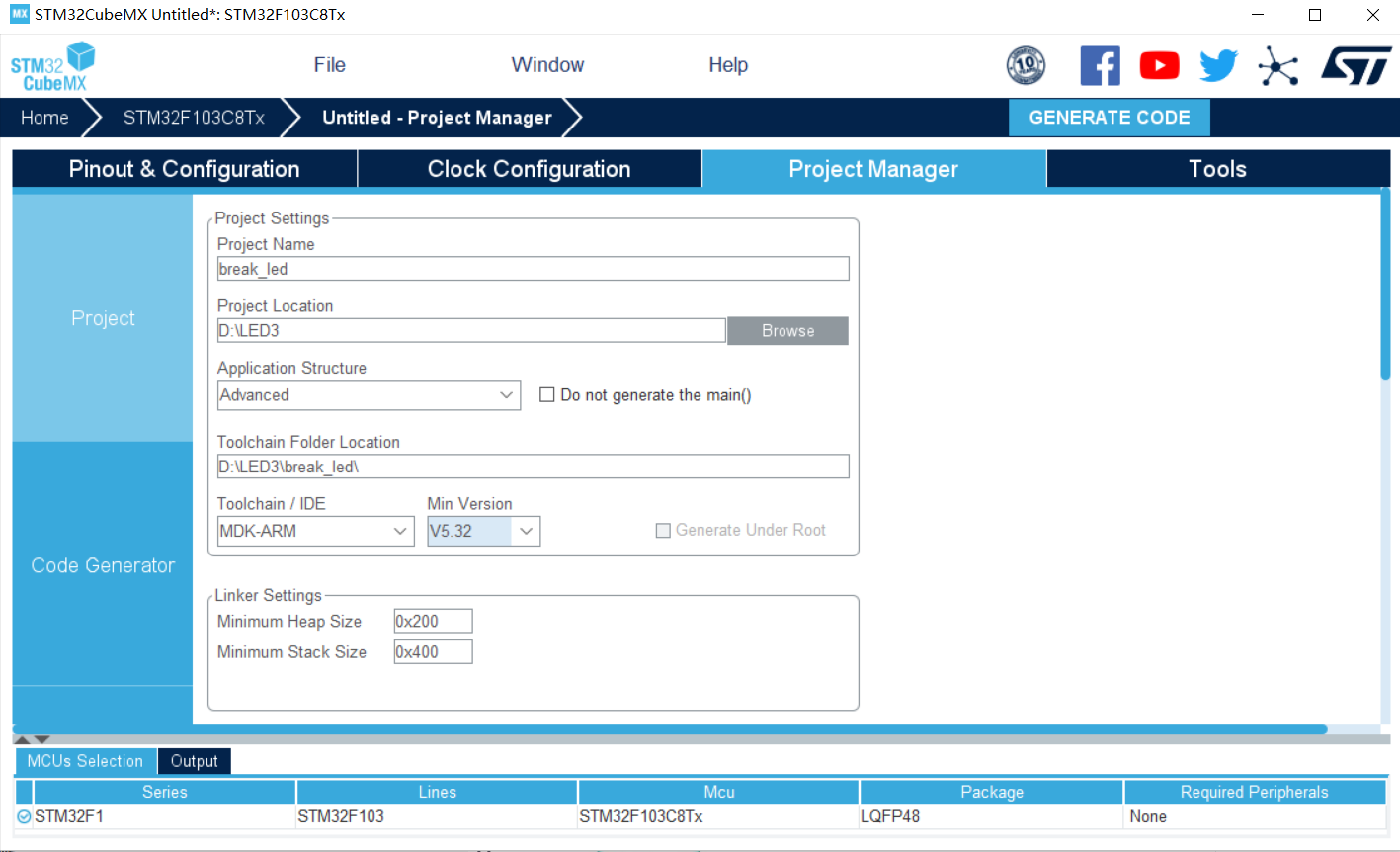
In the project, change toolchain to MDK-ARM, select the latest version, and choose the project name and project path by yourself
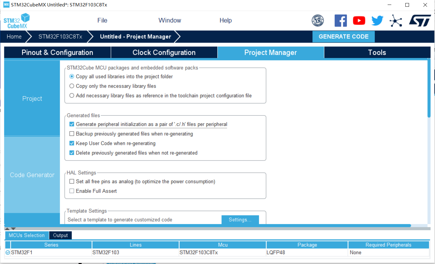
Select generate initialization file, and then select generate code
2. Code
The interrupt service function can be found in the gpio.c file in the Keil file
void HAL_GPIO_EXTI_IRQHandler(uint16_t GPIO_Pin)
When the rising edge is captured and an interrupt is triggered, it will enter this function
Then Hal will be executed_ GPIO_ EXTI_ Callback (gpio_pin) function. This function is a callback function. When we open it, we can find a break in front.
Before line 561__ weak indicates that this function is a virtual function and needs to be rewritten by the user.
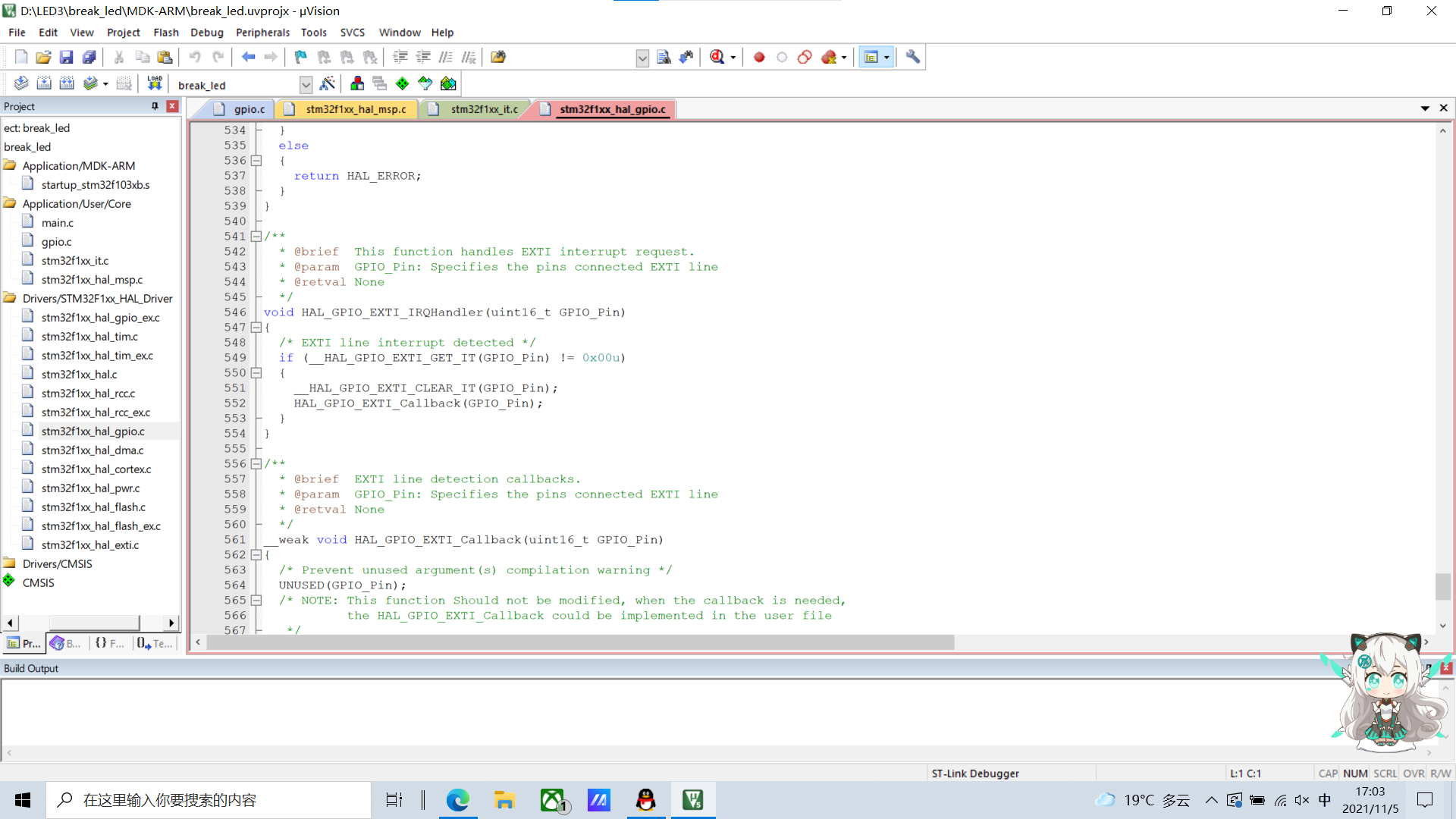
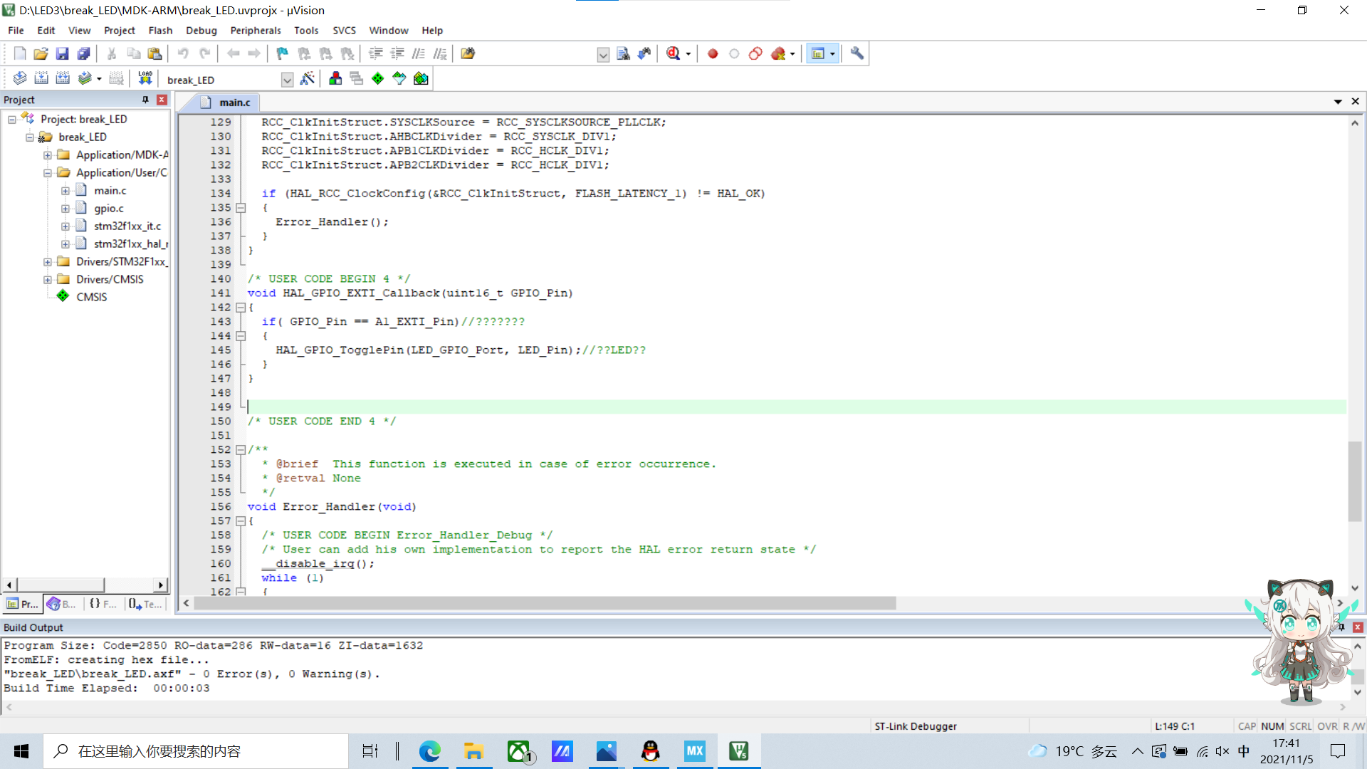
So let's rewrite it somewhere in the main.c file.
The position is below the main function.
void HAL_GPIO_EXTI_Callback(uint16_t GPIO_Pin)
{
	if( GPIO_Pin == A1_EXTI_Pin)//Determine external interrupt source
	{
		HAL_GPIO_TogglePin(LED_GPIO_Port, LED_Pin);//Flip LED status
	}
}

Compile it. There's nothing wrong
Burn the code into the C8T6 core board.

3. Circuit and effect
GPIO defaults to 3.3V high level. When the key is pressed, GPIO changes to low level, which is the falling edge. When the key is released, GPIO changes to high level again, which is the rising edge. Because the rising edge interrupt is set, that is, when the key is released, the light will change.
3, Serial port interrupt mode
1. Interrupt
(1) What is an interrupt

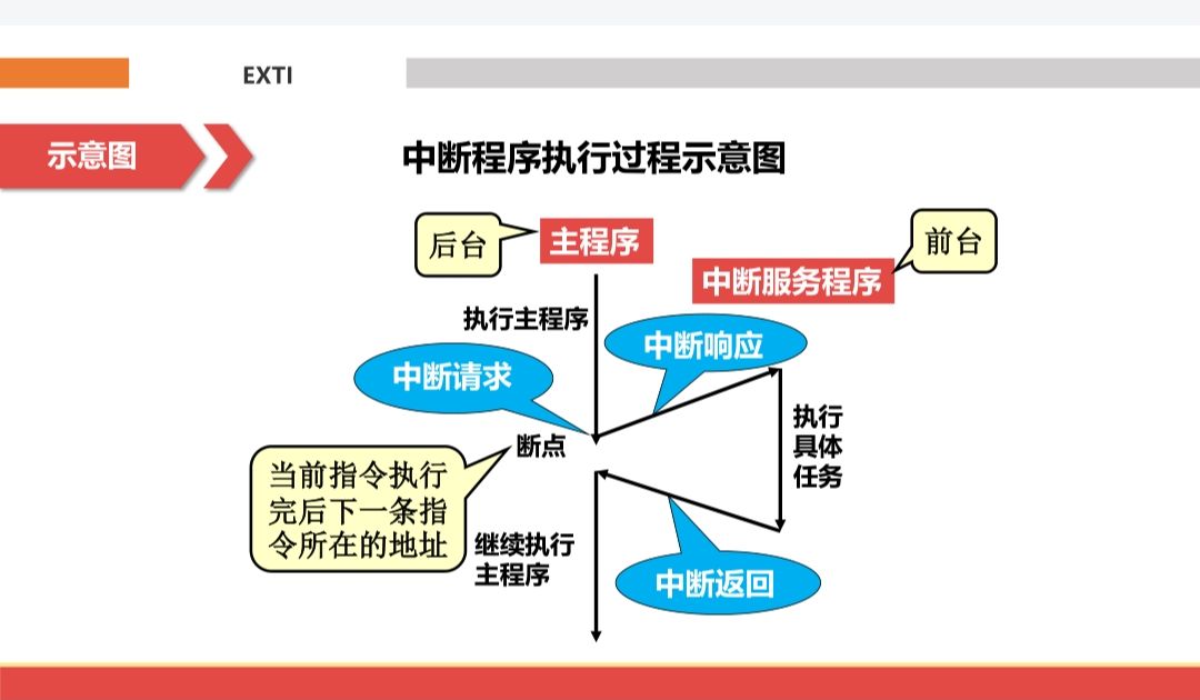
An interrupt is usually defined as an event that can change the order in which the processor executes instructions. Such events correspond to the electrical signals generated by the internal and external hardware circuits of the CPU chip. Interrupt refers to the process in which any unusual or unexpected urgent processing event occurs in the system during the execution of the computer, so that the CPU temporarily interrupts the currently executing program and turns to execute the corresponding event handler. After processing, it returns to the original interrupted place to continue execution or schedule the execution of a new process.
Interrupts are divided into synchronous interrupts and asynchronous interrupts. Synchronization interrupt: it is generated by the control unit when the instruction is executed. It is called synchronization because the CPU will issue an interrupt only after the execution of an instruction is terminated. Asynchronous interrupt: it is randomly generated by other hardware devices according to the CPU clock signal.
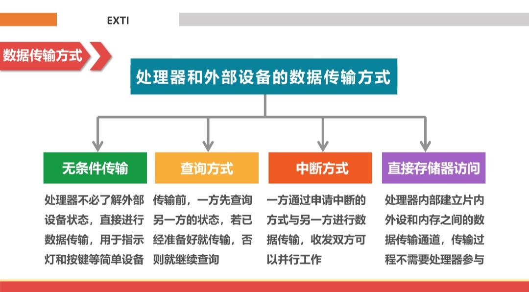
Interrupt data transmission mode:
Interrupt program execution process:
Interrupt response process:

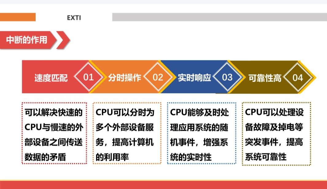
(2) Interrupt action
(3) Interrupt priority

Types of interrupts: hard interrupt and soft interrupt. Hard interrupt: an interrupt generated by the processor interrupt signal line. Soft interrupt: an interrupt triggered by an illegal instruction or a special instruction.
Interrupt priority: when multiple interrupts occur at the same time, the processor responds to the interrupt with high priority first; When ISR of low priority interrupt is executed, it can be interrupted again by high priority interrupt; ISR has higher execution priority than App Code.
2. Engineering setting
Set RCC: set high-speed external clock HSE and select external clock source
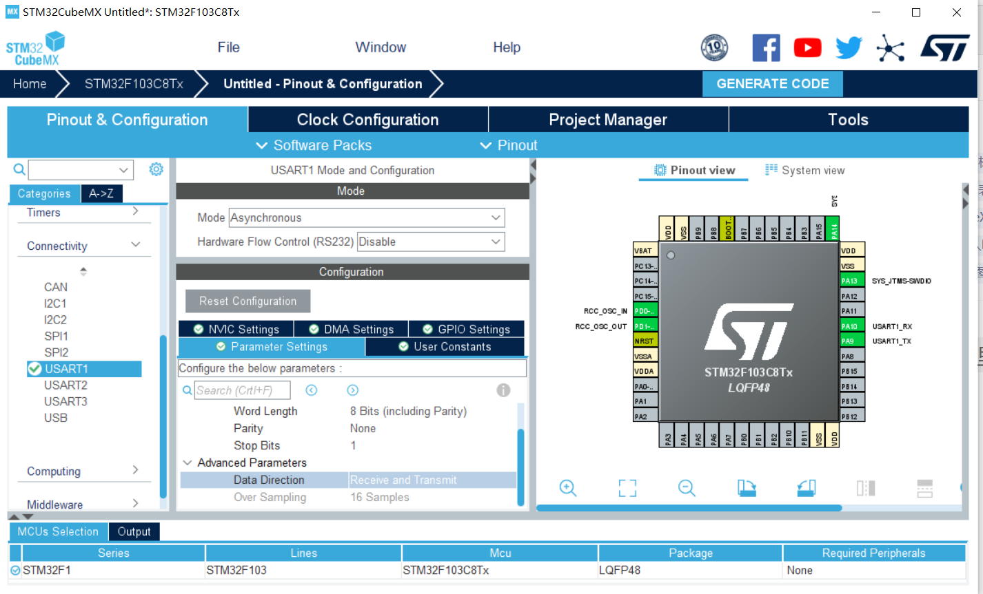
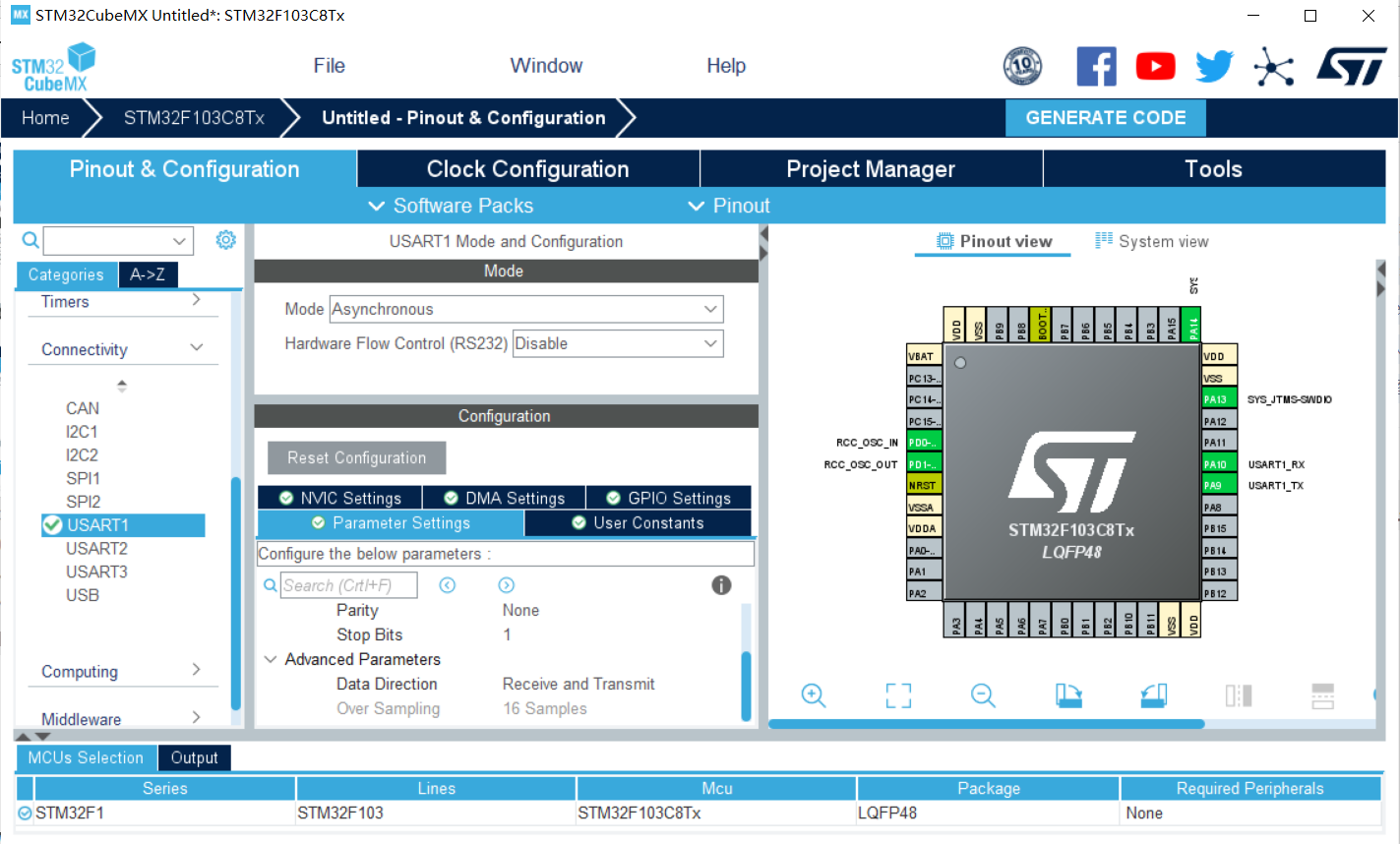
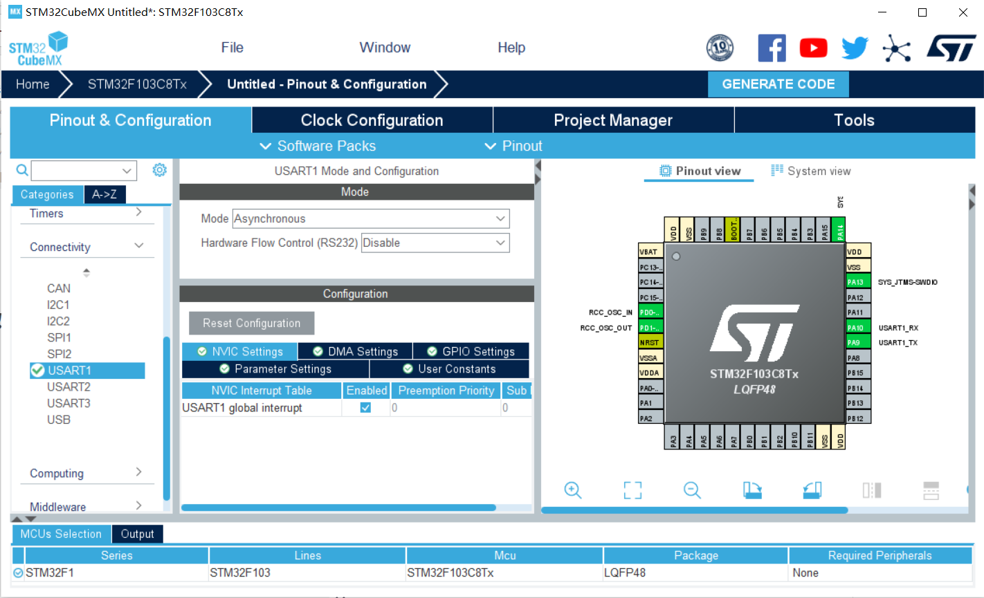
Set serial port:
1) Click USART1
2) Set MODE to asynchronous communication
3) Basic parameters: baud rate is 115200 Bits/s. The transmission data length is 8 bits. Parity check none, stop bit 1, both receive and transmit are enabled
4) GPIO pin setting USART1_RX/USART_TX (it is generally set automatically here)
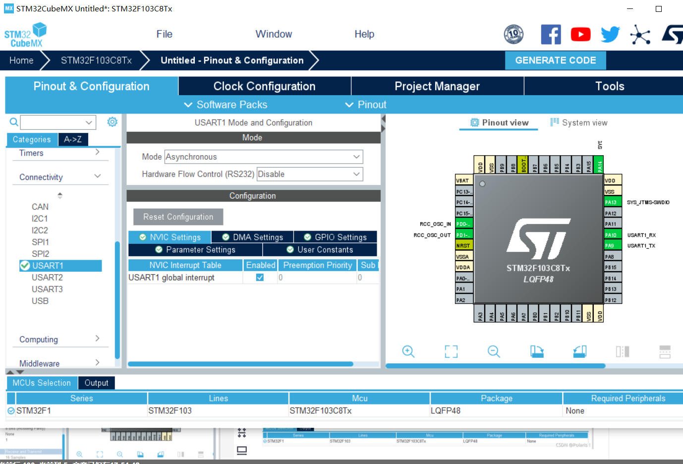
5) The NVIC Settings column enables to receive interrupts
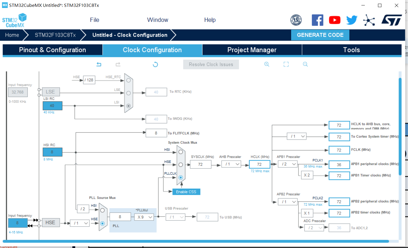
Clock setting
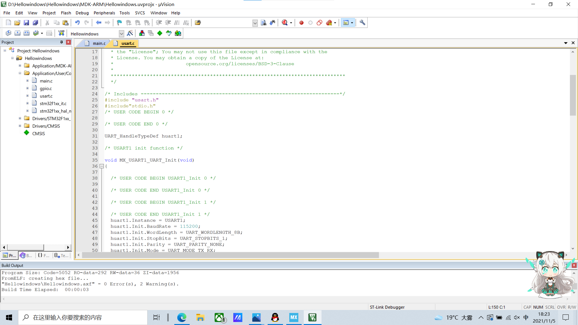
3. Code
printf function settings
Add header file #include "stdio.h" in main.c and usart.c
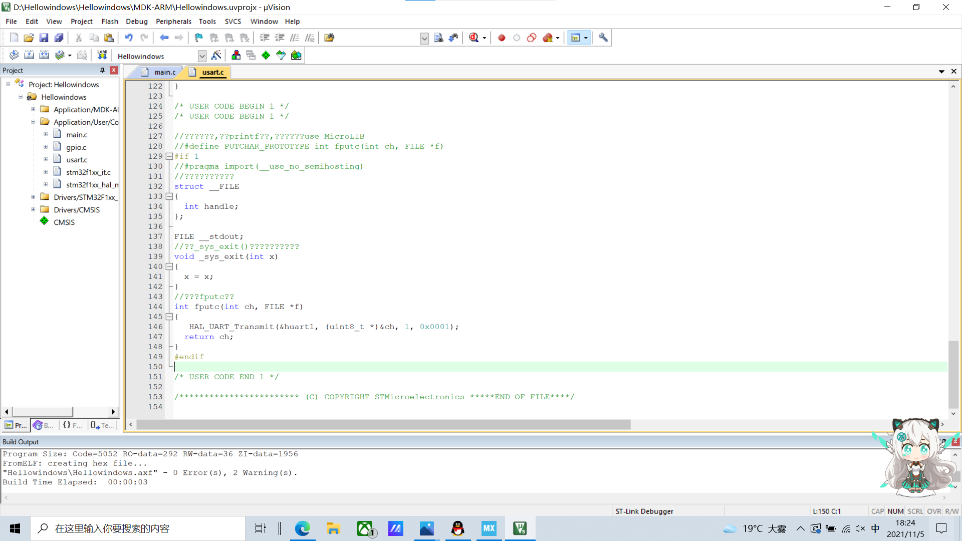
Then, add the following code to the usart.c file for redefinition
/* USER CODE BEGIN 1 */

//Add the following code to support the printf function without selecting use MicroLIB
//#define PUTCHAR_PROTOTYPE int fputc(int ch, FILE *f)
#if 1
//#pragma import(__use_no_semihosting)
//Support functions required by the standard library
struct __FILE
{
	int handle;
};

FILE __stdout;
//Definition_ sys_exit() to avoid using half host mode
void _sys_exit(int x)
{
	x = x;
}
//Redefine fputc function
int fputc(int ch, FILE *f)
{
	 HAL_UART_Transmit(&huart1, (uint8_t *)&ch, 1, 0x0001);
	return ch;
}
#endif

/* USER CODE END 1 */
In the main.c main function, add send data
    /* USER CODE END WHILE */
	  	printf("Hello windows!\r\n");
		HAL_Delay(500);
    /* USER CODE BEGIN 3 */
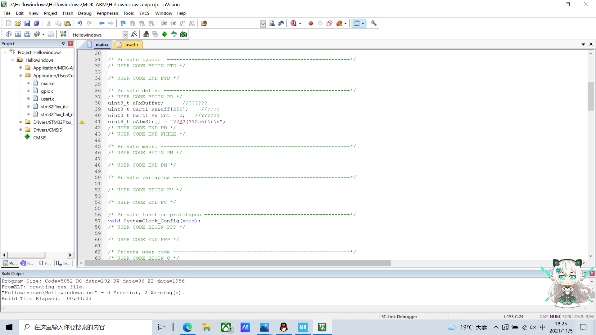
Add the following definition in main.c to receive serial port data
uint8_t aRxBuffer;			//Receive interrupt buffer
uint8_t Uart1_RxBuff[256];		//Receive buffer
uint8_t Uart1_Rx_Cnt = 0;		//Receive buffer count
uint8_t	cAlmStr[] = "data overflow (Greater than 256)\r\n";
Add a statement that turns on receiving interrupts
/* USER CODE BEGIN 2 */
	HAL_UART_Receive_IT(&huart1, (uint8_t *)&aRxBuffer, 1);
/* USER CODE END 2 */
Add interrupt callback function in the lower part of main.c
/* USER CODE BEGIN 4 */
/**
  * @brief  Rx Transfer completed callbacks.
  * @param  huart pointer to a UART_HandleTypeDef structure that contains
  *                the configuration information for the specified UART module.
  * @retval None
  */
void HAL_UART_RxCpltCallback(UART_HandleTypeDef *huart)
{
  /* Prevent unused argument(s) compilation warning */
  UNUSED(huart);
  /* NOTE: This function Should not be modified, when the callback is needed,
           the HAL_UART_TxCpltCallback could be implemented in the user file
   */

	if(Uart1_Rx_Cnt >= 255)  //Overflow judgment
	{
		Uart1_Rx_Cnt = 0;
		memset(Uart1_RxBuff,0x00,sizeof(Uart1_RxBuff));
		HAL_UART_Transmit(&huart1, (uint8_t *)&cAlmStr, sizeof(cAlmStr),0xFFFF);
	}
	else
	{
		Uart1_RxBuff[Uart1_Rx_Cnt++] = aRxBuffer;   //Receive data transfer

		if((Uart1_RxBuff[Uart1_Rx_Cnt-1] == 0x0A)&&(Uart1_RxBuff[Uart1_Rx_Cnt-2] == 0x0D)) //Judgment end bit
		{
			HAL_UART_Transmit(&huart1, (uint8_t *)&Uart1_RxBuff, Uart1_Rx_Cnt,0xFFFF); //Send the received information
			Uart1_Rx_Cnt = 0;
			memset(Uart1_RxBuff,0x00,sizeof(Uart1_RxBuff)); //Empty array
		}
	}

	HAL_UART_Receive_IT(&huart1, (uint8_t *)&aRxBuffer, 1);   //Restart receive interrupt
}
/* USER CODE END 4 */

Compile successfully, start burning

4. Serial assistant communication uses XCOM for communication
Communicate with XCOM

4, Introduction to HAL UART function library
UART structure definition: UART_HandleTypeDef huart1;
Serial port send / receive function:
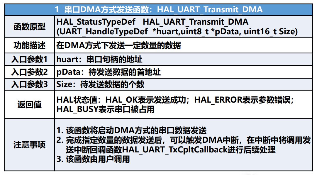
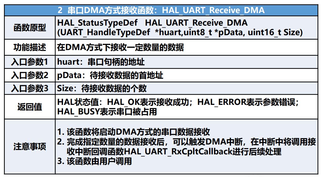
HAL_UART_Transmit();Serial port sends data, using timeout management mechanism
HAL_UART_Receive();The serial port receives data and uses the timeout management mechanism
HAL_UART_Transmit_IT();Serial port interrupt mode transmission
HAL_UART_Receive_IT();Serial port interrupt mode reception
HAL_UART_Transmit_DMA();Serial port DMA Mode send
HAL_UART_Transmit_DMA();Serial port DMA Mode reception
Function: serial port sends data of specified length. If the timeout is not completed, it will not be sent and the timeout flag (HAL_TIMEOUT) will be returned
Serial port interrupt function:
HAL_UART_IRQHandler(UART_HandleTypeDef *huart); //Serial port interrupt processing function
HAL_UART_TxCpltCallback(UART_HandleTypeDef *huart); //Serial port sending interrupt callback function
HAL_UART_TxHalfCpltCallback(UART_HandleTypeDef *huart); //Serial port sends half interrupt callback function (less used)
HAL_UART_RxCpltCallback(UART_HandleTypeDef *huart); //Serial port receive interrupt callback function
HAL_UART_RxHalfCpltCallback(UART_HandleTypeDef *huart);//The serial port receives half of the callback function (less used)
HAL_UART_ErrorCallback();Serial port receiving error function
Function: after the interrupt of HAL library is completed, it will not exit directly, but will enter the interrupt callback function. The user can set the code in it. After the serial port interrupt is received, it will enter the function. The function is empty and needs to be modified by the user.
Serial port query function: HAL_UART_GetState(); Judge whether the receiving of UART is over or whether the sending data is busy.
5, DMA
1. DMA introduction
DMA(Direct Memory Access) is an important feature of all modern computers. It allows hardware devices with different speeds to communicate without relying on a large amount of interrupt load of CPU. Otherwise, the CPU needs to copy the data of each segment from the source to the register, and then write them back to the new place again. During this time, the CPU cannot be used for other work.
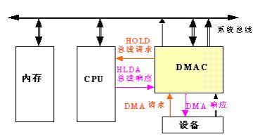
DMA principle:
DMA transfers copy data from one address space to another. When the CPU initializes the transfer action, the transfer action itself is implemented and completed by the DMA controller. A typical example is to move a block of external memory to a faster memory area inside the chip. Operations like this do not delay the processor, but can be rescheduled to deal with other tasks. DMA transmission is very important for efficient embedded system algorithms and networks.
When realizing DMA transmission, the DMA controller is directly in charge of the bus. Therefore, there is a problem of bus control transfer. That is, before DMA transmission, the CPU shall hand over the bus control to the DMA controller, and after DMA transmission, the DMA controller shall immediately hand over the bus control back to the CPU. A complete DMA transmission process must go through four steps: DMA request, DMA response, DMA transmission and DMA end.
2. DMA transmission
The function of DMA is to realize the direct transmission of data, which eliminates the link that the traditional data transmission requires the participation of CPU register. It mainly involves four kinds of data transmission, but it is essentially the same. It is transmitted from one area of memory to another area of memory (the data register of peripheral device is essentially a storage unit of memory). Data transmission in four cases is as follows:
Peripheral to memory
 Memory to peripherals
 Memory to memory
 Peripheral to peripheral
Normal mode: after the transfer is completed (i.e. the number of data to be transferred reaches zero), DMA operation will no longer occur. If a new DMA transfer is started, restart the DMA transfer when the DMA channel is closed.
Loop mode: can be used to process ring buffers and continuous data streams (e.g. ADC scan mode). When the cycle mode is activated, at the end of each round of transmission, the amount of data to be transmitted will be automatically loaded with the set initial value and continue to respond to DMA requests.
DMA transmission parameters: the source address of the data, the destination address of the data transmission location, the data transmission volume of the transmitted data, and the transmission mode of the number of transmissions.
When the user sets the parameters, mainly involving the source address, target address and the amount of transmitted data, the DMA controller will start data transmission. When the remaining amount of transmitted data is 0, it will reach the transmission end point and end DMA transmission. Of course, DMA has circular transmission mode. When it reaches the transmission end point, it will restart DMA transmission. In other words, as long as the amount of data remaining to be transmitted is not 0 and DMA is in the startup state, data transmission will occur.
Four elements of DMA data transmission:
① Transmission source: the source of DMA data transmission.
② Transmission target: the purpose of DMA data transmission.
③ Transmission quantity: the quantity of DMA transmission data.
④ Trigger signal: the action of starting a DMA data transmission.
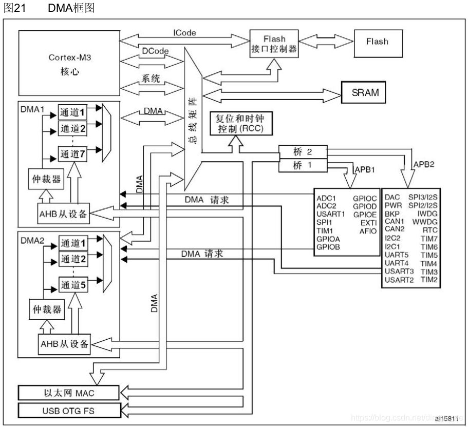
DMA working block diagram:
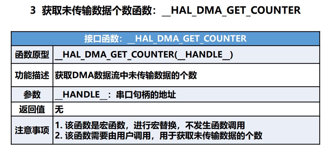
3. DMA mode interface function
6, Serial port sends data to the host computer in DMA mode
1. Setup project

Setting RCC

Set serial port
Enable interrupt
DMA Settings: click Add in DMA Settings to Add a channel, and set the transmission rate to Medium speed.
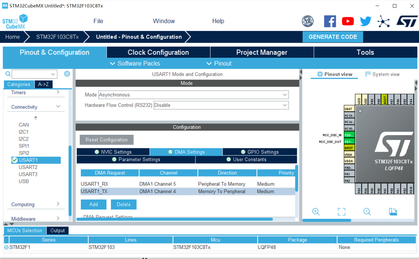
Set the mode to Normal and select Memory on the right

Select DMA under System view

Clock setting

2. Code
Add code in the main.c file
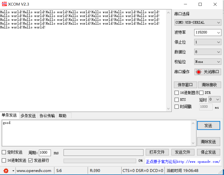
uint8_t Senbuff[] = "Hello world!"; //Define data sending array

  HAL_UART_Transmit_DMA(&huart1, (uint8_t *)Senbuff, sizeof(Senbuff));
  HAL_Delay(1000);

Burn

3. Serial port sending data
7, Experimental summary
Through this experiment, we learned a lot of new things. We also know that DMA will not occupy CPU resources in the process of transmission. It can run other tasks while transmitting. We also encountered many problems in the process of the experiment, but we found information and big man blog on the Internet and got a solution. In short, this experiment has gained a lot.
8, References
https://blog.csdn.net/as480133937/article/details/104827639/
https://www.cnblogs.com/breezy-ye/articles/12157442.html
https://blog.csdn.net/junseven164/article/details/121071585?spm=1001.2014.3001.5501
https://blog.csdn.net/junseven164/article/details/121066120?spm=1001.2014.3001.5501